1
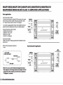
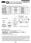
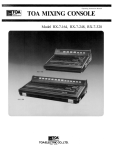
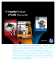
USER’S MANUAL
AMPLIFIERS:
MAXP 1200 / 1055D / 1201D / 1601D / 2051D / 2055D / 2651D
AMPLIFIER FEATUER DESCRIPTIONS
~I055D/~IZOID/~160ID
~IZOO
~Z05ID/~Z65ID/~Z055D
o
~,
~.
I. Une Out RCA Jacks· The LINE OUT allows you to build multiple amplifier systems
without having to use splitter cords to distribute the signal. Now it is simple a matter of
bringing one set of RCAs into the first amplifier, then using the line out RCA jacks as the
feed to the next amplifier.
5. Brigde Mode
6. Variable Bass Boost Control· 0 - + 10dB
Always use high quality shielded RCA cables.
3. Input Level Controls· Enables the matching of input levels to the output levels
from the head unit! or other signal source).
4. Phase Shift· Allows you to change the phase of your subwoofer from 0 to 180
7. Variable Subsonic Filter· 15Hz-35Hz
8. Low Pass Filter· When Crossover Mode Selector is in Low Pass Mode, this control
limits the frequencies which will be distributed to the speakers to those below the
value to which this is set within the range 35Hz-250Hz.
9.Power & Protection Indicator.. Provde instant information on status of amplifier,
including short-circuit and thermal overload alerts.
degrees to help compensate for timing differences between drivers.
10. Balanced input: Accepts line level balanced input from 0.4v to
Z. Line Input RCA .Jacks - These inputs are for signal cables from the source.
18v.
Amplifier Feature Descriptions:
BAlANCED INPUT: Accepts balanced line inputs from 0.4 volts to 18 volts.
LINE INPUT: The Line Inputs are the RCA input jacks labeled "LINE INPUr. This is where
the Radio/CD player RCA outputs connect to. The line Inputs accept unbalanced RCA inputs
from 0.2 volts to 9 volts.
UNE OUTPUT: The Line Outputs are a direct pass·through from the inputs. The RCA input
signal from the radio/CD player is routed through the amplifier and out of the Line Outputs.
The outputs would connect to another amp Line Inputs in a multi-amp set-up. This allows you to
daisy chain multiple amps from a single set of RCA cables from the radio/CD player.
LEVEL: The input level control allows you to match the amplifier input sensitivity to the
output level of the RADIO/CD player from 0.2 Volts to 9 volts when using unbalanced RCA
cables. The level control needs to be adjusted to match the line level Sensitivity fthis is the
amount of voltage the radio/CD player RCA's provide. Example: If the radio/CD player Line
level Sensitivity is 4 volts, adjust the amp level control to 4 volts
SUBSONIC: The variable SubsoniC filter is for subwoofer applications that require very low
tuning frequencies typically around 15Hz - 35Hz.
BASS EQ: Variable Bass Boost from 0 to 1OdB at a fIXed 45Hz.
LOW PASS: Fully adjustable crossover from 35 to 250Hz.
PHASE SHIFT: The Phase Shift is fully adjustable from 0 to 180 degrees and this allows you to
control the timing of the subwoofers. This is commonly used when the subwoofers are installed
in each front door.
SYSTEM DIAGNOSnCS: The amplifier has built-in monitoring devices and protection
circuits that monitor all vital functions of the amplifier. The Protection light does not come on
to indicate there is a failure, it comes on when it detects an improper operation. Common
issues that cause.
Protection status are:
- THERMAL: The amp has an internal temperature sensor that will automatically shut off the
amp if it reaches dangerous temperature levels.
- OVER LOAD: If the amp is run at an improper impedance, the amp will shut down. If you are
-CUPPING- speakers / subwooferfsJ, the light will blink to indicate a hard Clip.
• DC PROTECT: In the unlikely event the amp should internally fail, the amp will shut down
to prevent a DC voltage output to the speakers or sub.
REMOTE: The Remote Module plugs into the Remotejack and allows you to adjust
the level.
MAXPI ZOO MONO BLOCK AMPLIFIER APPLICATIONS
Basic application
Interconnect cable checklist:
- Connect the line inputs to a Radio/CD RCA outputs or line
output of the full range primary amplifier with good quality
RCA cables. A "Y" adapter may be needed as shown in the
diagram.
- Use at least 16 gauge speaker wiring. These amplifiers have
dual speaker terminals, simplifying the hookup of multiple
speakers
Crossover frequency control checklist:
- LOWPASS: 35Hz to 250Hz
- SUBSONIC: 15Hz to 35Hz
- BASS EO: 0 to 1OdB
- PHASE: 0 to 180 degrees
Level control checklist:
- Refer to the section 'Setting up systems after installation for
best performance-
Minimum final loudspeaker impedance:
- 1 ohm.
/------------------,
I
FULL RANGE
Dual Subwoofer Application
I
STEREO UNE INPUT
Y-ADAPIOR
---C:
0
o
----+
~
\
I
NOT USED
I
------------------~
*Note: You can use the Radio/CD designated
mono line output or a full range stereo line
output. For full range stereo line output, you
will need an optional 'Y-Adaptor" as shown
-_.
-TOM.nmn'+I2V
II CHAllIS GIIOWm
~PI055D/~PI201D/~PI601D/~P2051D/~P2651D
~P2055D
MONO BLOCK CLASS D AMPLIFIER APPLICATIONS
Basic application
Interconnect cable checklist:
- Connect the line inputs to a Radio/CD RCA outputs or line output
of the full range primary amplifier with good quality RCA cables.
A "Y" ada per may be needed as shown in the diagram.
- Use at least 16 gauge speaker wiring. These amplifiers have dual
speaker terminals, simplifYing the hookup of multiple speakers
_0
8UBWOOFER
nl!RBJU1I1!
."""'"
a
Crossover frequency control checklist:
- lOWPASS: 35Hz to 250Hz
- SUBSONIC: 15Hz to 35Hz
- BASS EO: 0 to 10dB
- PHASE: 0 to 180 degrees
TOBATTERY+1JV
w" ....
"'CAR.,....
AUTO ANTENNA
level control checklist:
- Refer to the section ' Setting up systems after installation for best
performance"
Minimum final loudspeaker impedance:
-I ohm.
Dual Subwoofer Application
, --------- ---------,
I
\
FULL RANGE
STEREO LINE INPUT
....
........ ............
"""""""'-....)
-,-,-_
SUIIWOOFER
-"
I
--c--
. 00
SUIIWOOFER
= NOTUSED
---------'"
*Note: You can use the Radio/CD designated mono
line output or a full range stereo line output. For full
range stereo line output, you will need an optional
ny-Adaptor'" as shown
~
SETTING UP SYSTEMS AFTER INSTALLATION FOR BEST PERFORMANCE
General:
At this point you are ready to get more specific on the settings for your amplifier.
Subsonic:
This setting acts as a low frequency cut off for your system bass reproduction. The point that you set it at cuts off any frequencies from reproduction
beyond this point. The 12 o'clock position is a great starting point. EXAMPLE: If you adjust the Subsonic to 25Hz, the amplifier will not play frequencies
below 25Hz but will play frequencies from 25Hz to the chosen Low Pass frequency.
8assEQ:
This setting is a fixed bass boost at 45Hz that is variable from 0- I OdB. This feature provides impact to your bass, but if not adjusted correctly, it can be
over used and cause damage to your subwoofers and amplifiers. It is best to slowly turn this setting clockwise until the desired punch is felt. it is not
recommended to exceed the 12 o'clock position unless listening at a low volume or a low recording quality as this can result in high distortion and
possibly clipping.
Low Pass:
The Low pass control acts as a ceiling and doesn't allow frequencies to the right of the desired setting to be reproduced. The 12 o'clock position is a
great starting point. EXAMPLE: If you adjust the Low Pass to BOHz, the amplifier will not play frequencies above 80Hz but will play frequencies from
80Hz to the chosen Subsonic frequency.
Phase:
The variable Phase adjustment allows you to change the relative time that the waveform meets your ear. With standard subwoofer installations where
the subwoofer is behind you, the Phase should generally be at O. When subwoofers or woofers are in the kick panels or door panels, the Phase
adjustment is useful in delaying the timing of the wave meeting your ear by adjusting the potentiometer to I BO degrees.
LeveIIGAlNJ Control Setup:
Ensure that the Level is turned completely to the left prior to turning the system on. Next you should insert a CD or cassette that you are familiar with
to use as a reference, and turn the head unit volume control to about 80% of its full setting. The system sound level will of course be very low, and the
following procedures will help you to match the amplifier input sensitivities properly to the head unit output signal level. It is important to match the
amplifier LEVEL input sensitivity to the Radio/CD output sensitivity. This can be located in the Radio/CD manual. If the Radio/CD output sensitivity is
2 volts, then adjust the amplifier LEVEL input to 2 volts.
If you are not sure what the Radio output sensitivity is, follow these general guide lines:
Turn the level control up slowly, till you hear distortion, then back off a few degrees on the control. If at any point your amplifier goes into protection,
you will need to turn the Level to the left a bit and then try again. If you reach a point where the output does not increase, stop turning the Level
control to the right as the amplifier/subwoofer combo has reached its maxx output in this application.
Lanzar MAX PRO SERIES AMPLIFIER FEATURES
output Power Rating
MAXPI200 MAXPIOSSD MAXPI20lD MAXPI60lD MAXP20SID MAXP205SD MAXP26SID
4Ohmload
2-Ohm load
450xl
900xl
Ix250W
lx500W
Ix500W
Ix 1OOOW
Ix750W
lx1500W
lxl000W
lx2000W
lx625W
lx1250W
lx1250W
lx2500W
l-Ohm load
O.S-Ohm load
1800xl
NA
lxl000W
lx2000W
lx2000W
NA
lx3000W
NA
lx4000W
NA
lx2500W
lx5000W
lx5000W
NA
YES
>200
>95d8
<0.05%
YES
>300
>95dB
<0.50%
YES
>300
>95dB
<0.50%
0.2V-9V
0.04V- 18V
47k-Ohm
YES
>300
>95dB
<0.50%
0.2V-9V
0.04V- 18V
47k-Ohm
YES
>300
>95dB
<0.50%
0.2V-9V
0.04V- 18V
47k-Ohm
20k-Ohm
Yes
20k-Ohm
Electrical Specifications
Slow Un-Mute Tum-On (soft start)
Dampening Factor
Signal To Noise Ratio (A-weighted)
THD & Noise
Variable Input level Controllunbalanced)
Input Level Control ( balanced)
Input Impedance (un-balanced)
Input Impedance (balanced)
Power / Diagnostic L.E.D.
0.2V-9V
0.2V-9V
0.04V- 18V
47k-Ohm
0.04V- 18V
47k-Ohm
YES
>300
>95dB
<0.50%
0.2V-9V
0.04V- 18V
47k-Ohm
20k-Ohm
20k-Ohm
20k-Ohm
Yes
Yes
Yes
20k-Ohm
Yes
Yes
Yes
Yes
Yes
Yes
Yes
Yes
Yes
Yes
Yes
Yes
Yes
35Hz-250Hz
15Hz-35Hz
OdB-+ 10dB
Yes
35Hz-250Hz
15Hz-35Hz
OdB - + 10dB
Yes
35Hz-250Hz
15Hz-35Hz
OdB-+ 10dB
Yes
Yes
Yes
Yes
12 gao
4ga.
INCLUDED
Yes
Yes
Yes
12 gao
4ga.
INCLUDED
30Ax3
40Ax3
YES
>300
>95dB
<0.50%
0.2V-9V
0.04V- 18V
47k-Ohm
20k-Ohm
Yes
Yes
Yes
Yes
Yes
Yes
Yes
Yes
Yes
Yes
Yes
35Hz-250Hz
15Hz-35Hz
OdB - + 10dB
Yes
35Hz-250Hz
15Hz-35Hz
OdB-+ 10dB
Yes
35Hz-250Hz
15Hz-35Hz
OdB-+l0dB
Yes
35Hz-250Hz
15Hz- 35Hz
OdB-+ 10dB
Yes
Yes
Yes
Yes
12ga.
4ga.
INCLUDED
Yes
Yes
Yes
12 gao
4ga.
INCLUDED
Yes
Yes
Yes
Oga.
Oga.
INCLUDED
Yes
Yes
Yes
Oga.
Oga.
INCLUDED
Yes
Yes
Yes
Oga.
Oga.
INCLUDED
35Ax3
40Ax4
200A
(not included)
250A
(not included)
250A
(not included)
Protection:
DC. Speaker Short Thermal. Overload
Power Supply MOSFET
Audio Output MOSFET
Crossover:
Variable Low Pass Filter / 24dB
Variable Subsonic Filter / 24dB
Variable Bass EQ
Phase Shift (0 - + 180 degrees)
Cronnector Type:
Unbalanced Inputs (RCA)
Balanced Inputs (DIN)
Line Output (RCA)
Speaker Terminals (molded)
Power/Ground Terminals (molded)
Remote
Fuses:
Dimensions (W x H x L) Inches
IO.16 x 25b xIO.9I
W
W
W
IO.16 x 2.56 x12.8
W
W
W
TO.16 x 2.S6 xI2.BW
W
Note: All features sUbject to change without notice
W
IO.16 x 2.S6 xlS.6r
W
W
w
IO.16 x 2.S6 xla
W
w
TO. 16
w
w
x 2.S6 x21.7r
w
w
IO.16 x 2.S6 x2T.73
w
TROUBLESHOOTING
Before removing your amplifier, refer to the list below and follow the suggested procedures. Always test the speakers and their wires first.
AMPLIFIER WILL NOT POWER UP.
Check for good ground connection.
Check that remote DC terminal has at least 13.Bv DC.
Check that there is battery power on the +terminal.
Check all fuses.
Check that Protection lED is not lit. If it is lit shut off amplifier briefly and then repower it.
HIGH HISS OR ENGINE NOISE (ALTERNATOR WHINE) IN SPEAKERS.
Disconnect all RCA inputs to the amplifierlsJ.jf hiss/noise disappear>. then plug in the component driving the amplifier and unplug its inputs. If hiss / noise
disappear>. go on until the faulty/noisy component is found.
It is best to set the amplifier's input level as insensitive as possible. The best SUbjective SIN ratio is oblainable this way. Try to drive as high a signal level
from the head unit as possible.
PROTECTION LED COMES ON WHENtTHE AMPLIFIER IS POWERED UP.
Check for shorts on speaker leads.
Check that the volume control on the heiJd unit is turned down low.
Remove speaker leads. and reset the am/Jlifier. If the P otection LED still comes on. then the amplifier is faulty.
Check that the minimum speaker imped<lnce for that model is correct.
Check for speaker shorts.
Check that there is good airflow around the amplifier. In some applications, an external cooling fan may be required.
DISTORTED SOUND
Check that the level contrails) is set to match the signal Ie
Check that all crossover frequencies have been properly set.
LANZAR SPEAKERS
SPEAKER SYSTEM