1
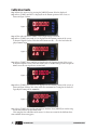
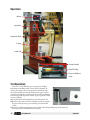
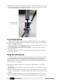
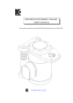
Push-Out Test Stand
User Manual
A
GESCHMIDT.COM • (513) 489-5130 • [email protected]
GESCHMIDT.COM
Push-Out Test Stand User Manual
Contents
About this Manual
1
Preface1
Calibration Guide
2
Operation3
Test Operation
3
Force Display Options
4
Using the Limit Function
4
Standard Setup Values
& Troubleshooting
5
Maintenance5
GESCHMIDT.COM
Contents
About this Manual
This manual is for use with G.E. Schmidt PROLINE™ Push Out Test Stands Only. This
manual contains procedures to calibrate a load cell to a meter. Should any pre-programed
values be accidentally changed at any time, see the Calibration Guide on how to reset
them back to the proper values for proper operation.
Sensor stations must be calibrated to the meter to ensure accuracy in the displayed
reading. Please read this entire manual prior to calibration.
Warning: The Meter and Load cell are fully calibrated in lbs.
before they leave the facility!
For technical questions, please contact: G.E. Schmidt, Inc.
11236 Williamson Rd.
Cincinnati, Ohio 45241
Phone: 513-489-5130
Fax: 513-489-5132
www.geschmidt.com
Preface
Conventions Used
This manual uses the following conventions to present the following information:
[TEXT IN BRACKETS] The label of a front panel button.
Display (Italics) Text that appears on the display, such as menu items.
Button Functions
Each button has different functions in RUN Mode and SETUP Mode.
RUN Mode (top to bottom)
MENU Switches back to real time display after the [MAX] has been pressed.
RST
Reset Tare function while in the operating screen
MAX Displays the maximum force reading on the operation screen.
TARE Adds a tare offset to the raw data of the attached data
MENU
RST
MAX
TARE
SETUP Mode
Entering and exiting the setup menu
Shifting to the right for decimals or numerals in the setup screen
Shifts through the setup menu or increments the value of a digit
Acts as the enter button in the setup menu.
Necessary Hardware
The following hardware is required for calibration of a sensor station:
n A force gauge capable of testing the accuracy of the meter.
1
GESCHMIDT.COM
About this Manual
Calibration Guide
Step 1: Enter the menu tree by pressing the [MENU] button, SEtuP is displayed.
Step 2: Press [TARE] until InP 1 is displayed on the bottom portion of the screen, as
shown in Figure 1 below.
Figure 1
Step 3: This value will remain ZERO, it is the input voltage at no load.
Step 4: Press [TARE] twice until d,5 1 is displayed on the bottom portion of the screen,
as shown in Figure 2 below. This value will remain zero lbs. — It is the load value displayed at 0mV input.
Figure 2
Step 5: Press [TARE] Twice until InP 2 is displayed on the bottom portion of the screen,
as shown in Figure 3 below. This value will be close to 30.00. This represents an input of
30mV across the two signal wires at max load.
Figure 3
Step 6: Press [TARE] twice until d,5 2 is displayed on the bottom portion of the screen, as
shown in Figure 4 below. This value will be the maximum force rating for the load cell.
Typically this rating will be 10,000 lbs.
Figure 4
Step 7: Press [TARE] once and the unit will save the data. Press [MENU] to exit the setup
screen and return to the operation mode.
This completes the calibration of the meter. See the next section for the different function available when testing parts.
2
GESCHMIDT.COM
Calibration Guide
Operation
Meter
Hydraulic
Hydraulic Ram
Frame
Load Cell
Pump Handle
Fluid Fill Plug
Pressure Release
Valve
Test Operation
There are several different types of projection welding.
Projection nut welding will be covered in this manual. In
order to do a proper test of a projection weld nut you will
need a bolt that fits the fastener welded to the part, a socket
of greater size than the overall size of the fastener in addition
to an already welded part nut combo. Steps to perform a weld
test are as follows:
Step 1: Thread the bolt through the panel and into the nut.
Step 2: Place the socket over the weld nut in order to support
the part while the nut is pressed off the part and into the
socket.
Step 3: Place all three components on top of the bolt head protruding out of the load cell.
The nut protrudes downward into the socket.
3
GESCHMIDT.COM
Operation
Step 4: You may either press the [MAX] button before or after the test. Be sure to re-tare
the unit before each test, so no value is stored in the maximum reading memory. Reference “Force Display Options” for this procedure.
Normal Push-Out
Test Stand setup.
Force Display Options
While the meter is in it run mode showing “XXXXX UNITS” the meter is displaying
the current force applied to the load cell. To display the peak force captured during a part
test press the [MAX] button once.
The screen will flash “Hi” periodically while you are in max reading mode. To return to
the live reading mode, press the [MENU] button once.
To clear the maximum value stored in the memory, re-tare the unit with no force applied to the load cell.
The highest value will be stored as the maximum force until the unit the unit has executed the tare function.
Using the Limit Function
The limit function can be used for quality control. For example, you wish for a welded
M6 nut to pass 800 lbs. every test. Set the first relay to 800 lbs., and the relay will close
every time 800 lbs. is passed. A number 1 would be lit right below the force reading to
indicate that the relay is closed. Four relays can be set and used for four different nut sizes.
See below on how to set up limits.
Step 1: Press the [MENU] button once and then the [TARE] button once to enter the
setup menu.
Step 2: Press the up arrow until you reach rELAY setup on the screen and press [Tare] to
enter the relay.
Step 3: Press [TARE] four times until you see Set 1 on the bottom of the screen. This will
be your set point for Limit 1, when the reading reaches above this value, limit one will
turn on.
Step 4: Press [TARE] twice until you see rSt 1 on the bottom of the screen. This will be
your reset value for Limit 1. The relay will de-energize when the force reading is below
4
GESCHMIDT.COM
Force Display Options
this value.
Step 5: Press [MENU] to exit the set up screen, or press [TARE] to continue setting up the
other available limits. The other limits are set up the same as relay one.
Below is an explanation of some of the terms you will find in the Relay Setup screen.
Act 1 (Action type 1) Action 1 is set as auto reset non-lathing. For the typical use of the
limit function, you will want to keep this set at auto.
FAiLSF (Fail safe operation) This should always be turned off.
dELAY (Delay for Relay) You can set a time delay for the relays to turn on or off. It can be
set from to 0 to 999.9 seconds. The relay will not come on or turn off, until the set or
reset values have been maintained for the delay time period.
Standard Setup Values & Troubleshooting
Several values have been programmed into your meter to accurately reflect the force
of the load cell. The following items detail the values that should be set in the Input Setup
menu, prior to leaving the facility.
Going into the setup by pressing [MENU] then [TARE], you will reach the setup
screen. Press [TARE] to scroll through the setup options listed below:
1st PoLar (Input) — press [TARE], this value should be uni (Uni-Polar)
2nd rAnGE (Input) — this value should be 30 mv (Range)
3rd rAtio (Input) — This should be set to no. No ratio compensation is needed from this
load cell.
4th d-SCAL (Dual-Scale Input) — This should be set to no.
5th unitS (Input) — This should remain in Lb unless desired units is different.
6th dEc Pt (Decimal Point Setup) — This should read ddddd.d which represents (#####.#
Lbs.).
7th ProG (Setup/Calibrate) — Press [TARE] to enter SCALE ProG, press [TARE] again to
enter Input 1.
Reference Chapter 1 on what the inputs and display readings should be.
TROUBLESHOOTING TIPS
While the meter leaves our facility pre-programmed and ready to use, here are some
helpful tips, should you set up the device and get faulty readings:
u Readings seem to be 1000 lbs. off. Go into the input set up and be sure that the rAtio
function is set to no.
u Readings seam extremely low. Go into the input setup, SCALE ProG and be sure that
Input 2 is set to 30.00mV and that d,5 2 is set to 10,000 lbs.
u Fault is displayed on the operation screen. Make sure the sensor wire is properly
connected to the meter and the load cell. For standard signal cable shipped with meter,
wiring into meter from left to right should be P+: Red , S-: White , S+: Green , COM:
Black.
Maintenance
The pump and ram need very little maintenance. Wipe down machine monthly to keep
excess dust from building up on the load cell and meter. Check monthly for proper fluid
level by removing the fluid fill plug and viewing the level of the oil inside. With the ram
fully retracted, fluid level should be level to the bottom of the threads of fluid plug.
5
GESCHMIDT.COM
Standard Setup Values & Troubleshooting