1
Delivering the Power of Vision
User’s Guide
7000 IP
VCS 5.0
Table of Contents
Getting Started ............................................……………….......…3
Quick Start Connection Guide …………………….……………..…4
Network Setup ………………………………………………..………5
Starting Up the System ………………………………..……………7
Videoconferencing ……………………………….………………….7
Videoconferencing – Placing Calls and Muting …………….…….8
Videoconferencing – Camera Control and Local IP …..….………9
Videoconferencing – Local Video and Send PC ………..………10
Information Input …………………………………….……………..11
Appendix A – Single Monitor and Dual Monitor Modes………….12
Appendix B – Configuration ……………………………………….13
Appendix C – System Monitor …………………………………….22
Technical Support ……………………………….…………………25
2
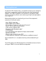
Getting Started
On behalf of VTEL Products Corp., we would like to thank you for making the
right choice in purchasing a powerful and feature rich video conferencing
endpoint. Your 7000 IP integrates a full featured PC, our powerful Video
Conferencing System software, and a wide range of input and output options
into a single unit.
Before getting started, you should verify you have all the components
necessary to install your system:
• Silver 7000 IP Codec Box
• Power adapter for the 7000 IP
• Wireless Mouse/Keyboard Combo (plus IR receiver)*
• Sony D-100 (or another camera source)*
• VTEL Camera Umbilical cable*
• Microphone with Microphone cable*
• A VGA Monitor*
• An S-Video Monitor (Not required, but highly recommended)*
• Speakers with cable*
• Ethernet cable (to attach to your LAN)*
• S-Video cables for attaching S-Video monitors or additional cameras*
Items marked with an (*) are optional and may not be included with your
7000.
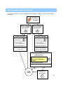
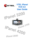
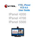
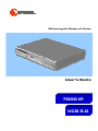
Consult the guide on the following page for an illustrated overview on how to
set-up your 7000 IP in the most common configuration.
3
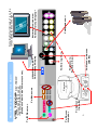
COM1
K
To Camera
Visca IN
To Power
Adapter
Printer Port
USB
USB
Camera
USB
USB
Lan Lan
To Ethernet
M
To IR Receiver
1
To Camera Power
(DC IN)
To Camera
S-Video Input
To Microphone
VGA
VGA Connection
To Primary Display
REV. 7000IP
* S-Video Cable Not Included
** Speaker Cable Not Included
(Headphone Mini to Speaker Receptacles)
VTEL 7000 IP
Quick Start Connection Guide
4
To Speakers**
S-Video Connection
To Secondary Display*
2
Note: By Default, Display 1 is on the
left and Display 2 is on the right!
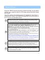
Network Setup
Once your 7000 IP has been physically installed and setup, you will need to
configure your network to allow the H.323 video conferencing traffic through
any firewalls.
Consult the guide on the following page for the appropriate steps to take in
setting up your network. Refer back to this page when you see the letters A,
B, or C for the exact procedure details.
A
B
By default, your IPanel is setup to use automatic IP detection (DHCP) on both of its Ethernet
ports. If your internal network is configured to use DHCP (which is the most common case)
then simply plug an Ethernet cable into either port on the IPanel.
• Once you have this information, open up the network properties page on the IPanel by
going to START->CONTROL PANEL->NETWORK CONNECTIONS on Windows XP
• RIGHT CLICK on "Local Area Connection" or "Local Area Connection 2" and select
PROPERTIES (see note below) One connection will say connected, one will say
network cable unplugged. Use the connected network choice.
• In the properties page LEFT CLICK on "Internet Protocol (TCP/IP)" to highlight it and then
press the PROPERTIES button.
• Toggle both selections from "Obtain...Automatically" to "USE THE FOLLOWING…” and
then enter the five pieces of information you gathered earlier into the appropriate boxes.
Once you've entered this information press OK to close the dialog.
• Verify network connectivity by selecting Internet Explorer on the IPanel and connecting to a
public web site (it is the same process as any other computer).
• Note: there are 2 Ethernet adapters on the back of the IPanel. You can use either one, but
if you are setting up a static IP address on your IPanel make sure you setup the same
network properties for the same port you plug your cable into. (Facing the back of the iPanel
adapter 1 is on the left ("Local Area Connection") and adapter 2 ("Local Area Connection 2")
is on the right. It's perfectly ok to set-up both adapters with the same information.)
C
Load VTEL's System Configuration tool. Configuration is located in the Windows Start Menu
in the VTEL program group. In Configuration under the Network tab, check the "Enable NAT"
box and enter your public/external IP address in the box (you may have to ask your
ISP/Network Administrator for this address). Press "OK" to close System Configuration and
apply the settings. These settings will take effect on the next call you place.
D
Consult your network administrator or your router/firewall’s manual for how to open these
specified ports for your 7000. To able to receive calls, you all also need to forward these ports
to the internal LAN address of the 7000.
5
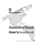
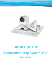
Network Setup (continued)
This decision tree covers all of the common network configuration conditions. See the previous page for
more details.
Is there a
Firewall?
NO
YES
Does network
use DHCP?
Does network
use DHCP?
A
A
NO
YES
YES
IPanel Settings
IPanel Settings
• IP Address
• Subnet Mask
NO
• IP Address
B
B
• Subnet Mask
• Default Gateway
• Default Gateway
• Preferred DNS Server
• Preferred DNS Server
• Alternate DNS Server
• Alternate DNS Server
Modem internal addresses
Source: ISP
Firewall internal addresses
Source: Network admin
Configure Firewall for
Videoconferencing
• Open TCP port 1718-1720
• Open TCP and UDP ports
5004-6004
D
• Forward traffic to IPanel
Does firewall do NAT?
NO
YES
OK
Enable NAT
on IPanel
C
6
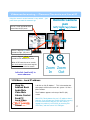
Starting Up the System
A. Turn on the system using the power
button on the far left of the VTEL 7000.
B. It will power up like any other Windows XP computer
going through familiar screens.
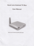
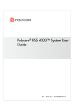
C. Once the 7000 has booted up, double click on the red “V ball” (“Start VTEL VCS” shortcut,
See Fig. 1) in the upper left corner. This launches the videoconferencing software.
Fig. 1: 7000 Desktop, Dual Display Mode, No VCS Running
Left Monitor (1)
Right Monitor (2)
Note: In a single monitor set-up everything launches on the left monitor. (See Appendix A for
changing between single monitor and dual monitor set-ups).
D. After a brief loading process, a large VTEL “V ball” appears on the lower right
of the screen and the right screen will change.
Videoconferencing
Left Monitor
Right Monitor
A. The screen at right will appear.
The left half is your local PC.
The right half is the videoconferencing section.
Note: The keyboard mouse works normally as a
PC mouse when the cursor is in the PC area…
and the keyboard mouse works as a videoconferencing
controller when the cursor is in the videoconferencing area.
B. Move the cursor to the right monitor (it will turn blue)
C. Right-click anywhere and the videoconferencing menu appears:
Note: Left-clicking on the V-Ball will produce the same menu.
Place a Call
Audio Mute
Video Mute
Volume Control
Local Video
My IP Address
Exit VTEL Now
Cancel
7
Videoconferencing - Placing Calls and Muting
Placing a call and Managing the address book
1. Call Rate
2. IP Address
192 or 256 is a good
rate for the Internet
Enter the IP address
you are calling
Use tabs to toggle
between hand dialer
and address book
3. Click “Dial”
Address Book
Speed Dial Keys
Hand Dialer
Hand Dialer – for ad-hoc connections
• Use this 3-step process when you just want to
connect to another site not in the address book.
• Call yourself in loop back by dialing your own IP
address to test that your system is working OK.
Place a Call
Audio Mute
Video Mute
Volume Control
Local Video
My IP Address
Exit VTEL Now
Cancel
Address Book– for routine connections
• From list -- Use your cursor to highlight in blue
the site and then “left double click”.
• Speed Dial – Place the cursor over the speed dial
key and “left click”
• Put any site on a Speed Dial key by highlighting
the horizontal entry and drag and dropping it onto a
key.
• To add a site -- Right click in the “address book”
(white) portion and bring up menu with “add” at the
top. This is how to add sites to your address book.
Videoconferencing Menu
An ICON appears on
your VC screen showing
status of audio and video mute
Muting -- On Master Menu click:
• Audio Mute so far site cannot hear you
• Video Mute so far site cannot see you
• Undo mute – click on the mute line on
Master Menu again or,
• Click on the ICON displayed on your VC
screen.
Volume: put your cursor where you
want the volume to go and left click.
Slide bar appears on PC side of screen
8
Videoconferencing – Camera Controls and Local IP
Using the mouse to control cameras is very natural … just
point where you want the camera to go.
Remote Camera
pan
Cursor is small and white when
moved into left (PC) zone
left/right/up/down
Cursor is big and blue when
moved into right (VC) zone
+
Cursor is big and yellow when
moved into PIP window (PIP) zone
When in PIP zone the cursor controls
your local camera in the same way the
blue cursor controls the far camera
Left-click (and hold) to
move cameras
-
Zoom Zoom
In
Out
VCS Menu – Local IP address
Hang Up
Address Book
Audio Mute
Video Mute
Volume Control
Send PC
Local Video
My IP Address
Cancel
Left-click on “My IP Address”. This is the number that
other people should call to reach this system. It’s like a
phone number.
The IP address appears on the top of the PC (left)
screen.
Note: VCS 5.0 only detects the user’s IP address when it
launches. If you change your IP while VCS 5.0 is running
it will not know about it and your calls won’t work. To
remedy this problem, just Exit VCS (by selecting Exit
VTEL Now), and then launch VCS 5.0 again.
9
Videoconferencing –Local Video and Send PC
Local Video shows what your local camera is seeing. It normally goes into a PIP
(Picture In Picture) window in the videoconferencing section (right side).
Hang Up
Address Book
Audio Mute
Video Mute
Volume Control
Send PC
Local Video
My IP Address
Cancel
Shows your video in PIP window
Show Local Video
Hide Local Video
Removes local video (PIP)
Dock/Undock PIP
• Undock: makes local video into
PC-style window. You can resize
and move anywhere
• Dock: removes top blue bar and
“docks” PIP window where you
last put it
move
Your local
picture
(undocked)
size
VCS Menu – Send PC
During a videoconference you can present PowerPoint slides (or any other PC application)
to the other participants. Any image on the PC side of the screen is sent to the far end!
For Example, PowerPoint:
Hang Up
Address Book
Audio Mute
Video Mute
Volume Control
Send PC
Local Video
My IP Address
Cancel
• Start your PowerPoint application in the left
(PC) side. Maximize the size of the slides locally.
• Right-click on the video (right) side and bring up
the videoconferencing menu
• Select “Send PC” – an ICON appears on your
video side.
• In about 10-15 seconds the far site conferencing
unit will also see your PowerPoint slide … exactly
the same as you see it (same size and quality)
• Click on your PowerPoint slide and it will
automatically (like normal) advance to the next
slide. In about 5-10 seconds the remote site will
see the new slide.
• When finished sharing slides select “Stop
Sending PC” from the main white menu.
Note: If you are sending PC slides to the far site
and they start “Send PC” at their end, it will cancel
your Send PC and you will start receiving their PC
data.
Note: The time it takes to transfer a slide is
dependent upon the bandwidth of the connection
between IPanel systems.
10
7000 – Information Input
Information input into VTEL 7000 can be achieved many ways:
1. Bring your flash drives to the meeting. Load your PC files into
the VTEL 7000. There is a convenient USB port on the front of
the system
2. From a CD or DVD via the drive on the front of the unit.
3. Retrieve your files from your LAN like any other computer on
the LAN. You can even email your file to your public (Internet
accessible) email address and download the file.
11
Appendix A – Dual Monitor and Single Monitor Modes
To change from single monitor to dual monitor mode follow these
steps:
A.
B.
C.
D.
E.
Exit VCS if it is running. You can do this by selecting the “Exit VTEL Now’ option from the
menu.
Navigate the mouse to the red and white ATI icon and right click on it. (See Fig. 2)
Now move the mouse to the Activate Profile menu, and another menu will appear. (See Fig. 2)
Finally move the mouse to the desired option and left click on it. (See Fig. 2)
Re-Launch VCS
Fig. 2: Changing the Display profile
D
Note: This can also be used to restore your display settings back to factory
defaults in case they are inadvertently altered.
C
B
12
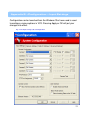
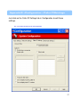
Appendix B –Configuration – Input Settings
Configuration can be launched from the Windows Start menu and is used
to configure various options in VCS. Pressing Apply or OK will put your
changes into effect.
Fig. 2: The Input Settings tab of Configuration
13
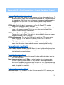
Appendix B –Configuration – Input Settings (cont.)
Camera Configuration: (see Fig. 2)
Camera 1…6: These boxes represent each camera you have attached to the unit. To
enable a camera simply select the input on the back of the 7000 your camera
is plugged into. When more than one camera is configured additional options
will appear in the right click VCS menu allowing you to change between
multiple cameras.
PTZ Enable: Check this box if your camera is a Pan-Tilt-Zoom (PTZ) capable
camera and the control cable is attached.
Address: This sets the PTZ address in a chain of PTZ cameras. Typically this is the
same as the camera number. This is for users who want to reorder their
cameras without having to re-wire them .
PTZ Protocol: This sets the PTZ protocol for the brand of camera being used.
Typically this is set to Sony. This option is only available if at least one camera
has been checked as a PTZ camera.
PTZ Port Assignment: This sets the COM port for which the PTZ camera control
cable is attached. On a 7000, this is typically COM1. On, a 7002 this is
typically COM2.
Camera Test: Pressing this button will test your PTZ camera setup. If your cameras
move when this button is pressed your cameras are configured correctly.
Camera Control: (see Fig. 2)
Allow Far End Camera Control (FECC): When this box is checked the far end can
control your local camera(s). Un-checking this box will no longer allow the far
side to control your local camera.
User Interface: (see Fig. 2)
Enable Advanced Mode: Checking this box will enable additional options from the
VCS right click menu.
Place Incoming Data on the VC Side: In a dual monitor set-up, incoming data
(H.239) is typically placed on the PC (left) monitor. Checking this box will
reverse this and place an incoming data share on the VCS (right) monitor and
move far end video to the PC. In a single monitor setup or in the Advanced UI
mode, this option has no effect.
Software Version: (see Fig. 2)
Software Version: The number in this box is the version of the VCS software your
system is running.
14
Appendix B –Configuration – Network Settings
Just click on the Network Settings tab in Configuration to edit these
settings.
Fig. 3: The Network Settings tab of Configuration
15
Appendix B –Configuration – Network Settings (cnt.)
NAT and Firewall Settings: (see Fig. 3)
TCP Ports: These two boxes allow the end user to change the default TCP port
range used by VCS. It is highly recommended to not make this range smaller
than 10 ports. The default range is 5004-6004.
UDP Ports: These two boxes allow the end user to change the default UDP port
range used by VCS. It is highly recommended to not make this range smaller
than 10 ports. The default range is 5004-6004.
Enable NAT: Check this box to enable NAT (network address translation) in VCS.
NAT Address: Enter the NAT address (typically your external IP) here. This address
is only used when Enable NAT is checked.
Gatekeeper Settings: (see Fig. 3)
Enable Gatekeeper: Check this box to enable the use of a gatekeeper.
Gatekeeper Address: Enter the address of your gatekeeper here. VCS will only use
this address if Enable Gatekeeper is checked.
Note: VCS will only log into a gatekeeper when it first boots up. To check
registration status see System Monitor (See Appendix C).
H.323 ID: Enter your H.323 ID here for use with a gatekeeper.
E.164 Address: Enter your E.164 address here for use with a gatekeeper.
Host Addresses: (see Fig. 3)
Computer Name: Your machine’s local networking computer name.
IP Address: Your machine’s local IP address.
Note: Your local IP is only detected when VCS starts up. If your local IP
address changes while VCS is running, then just quit VCS and then relaunch it.
Miscellaneous: (see Fig. 3)
Enable DNS Dialing: Checking this box enables the use of DNS names in the HandDialer and Address Book. For example, you can now type in demo.vtel.com
instead of 24.153.141.149.
Note: If you are experiencing trouble dialing while registered with a
gatekeeper, then try turning this feature off.
H.235 Security Mode: Sets the usage of H.235 encryption as follows:
None: Turns H.235 off. You will only be able to connect to unencrypted sites.
Auto: VCS will use AES encryption only if the far side supports it, otherwise
VCS will connect normally and unencrypted (recommended setting).
AES: VCS will only connect to sites that support H.235 AES encryption.
In-Conference System Name: This box allows you to set the name that other sites
will see for your machine in a videoconference.
16
Appendix B –Configuration – Caller ID Settings
Just click on the Caller ID Settings tab in Configuration to edit these
settings.
Fig. 4: The Caller ID Settings tab of Configuration
17
Appendix B –Configuration – Caller ID Settings (cnt.)
Auto Answer: (see Fig. 4)
Auto Answer Calls: When this box is checked the unit will automatically accept
incoming calls. When unchecked the user will be prompted to accept or reject
the incoming call.
Caller ID: (see Fig. 4)
No blocking or screening: When this option is selected the system will not block or
screen any incoming calls.
Screen calls: When this option is selected you will only accept calls from the list
below.
Block Calls: When this option is selected you will not accept calls from any site in
the list below.
Add: Use this button to add an IP address to the selected list.
Delete: Use this button to delete an IP address from the selected list.
Prompt for Site Add in: You will be prompted if you want to add a site to the
selected list.
Do not display incoming caller ID: Incoming caller ID will not be displayed when
this is checked.
Do not display local ID / number: When checked your local ID or number will not
be displayed.
18
Appendix B –Configuration – Advanced Settings
Just click on the Advacned Settings tab in Configuration to edit these
settings.
Fig. 5: The Advanced Settings tab of Configuration
19
Appendix B –Configuration – Advanced Settings (ct.)
Enabled Video Transmit Codecs: (see Fig. 5)
H.261: Un-checking this box will disable the system from sending or negotiating to
any type of H.261 one video.
Note: The system will still receive it.
H.263: Un-checking this box will disable the system from sending or negotiating to
any type of H.263 one video.
Note: The system will still receive it.
H.264: Un-checking this box will disable the system from sending or negotiating to
any type of H.264 one video.
Note: The system will still receive it.
Enabled Audio Transmit Codecs: (see Fig. 5)
G.711 A LAW: Un-checking this box will disable the system from sending or
negotiating to G.711 A LAW audio.
Note: The system will still receive it.
G.711 U LAW: Un-checking this box will disable the system from sending or
negotiating to G.711 U LAW audio.
Note: The system will still receive it.
G.722: Un-checking this box will disable the system from sending or negotiating to
G.722 audio.
Note: The system will still receive it.
G.722.1 24-bit: Un-checking this box will disable the system from sending or
negotiating to G.722.1 24-bit audio.
Note: The system will still receive it.
G.722.1 32-bit: Un-checking this box will disable the system from sending or
negotiating to G.722.1 32-bit audio.
Note: The system will still receive it.
G.723: Un-checking this box will disable the system from sending or negotiating to
G.723 audio.
Note: The system will still receive it.
G.728: Un-checking this box will disable the system from sending or negotiating to
G.728 audio.
Note: The system will still receive it.
G.729: Un-checking this box will disable the system from sending or negotiating to
G.729 audio.
Note: The system will still receive it.
20
Appendix B –Configuration – Advanced Settings (ct.)
Enabled Audio Transmit Codecs (continued): (see Fig. 5)
G.729 ANNEX D: Un-checking this box will disable the system from sending or
negotiating to G.729 ANNEX D audio.
Note: The system will still receive it.
G.729 ANNEX E: Un-checking this box will disable the system from sending or
negotiating to G.729 ANNEX E audio.
Note: The system will still receive it.
AAC 64-bit: Un-checking this box will disable the system from sending or negotiating
to AAC 64-bit audio.
Note: The system will still receive it.
AAC 128-bit: Un-checking this box will disable the system from sending or
negotiating to AAC 128-bit audio.
Note: The system will still receive it.
Video Transmit Codec Cutoffs: (see Fig. 5)
H.261 Limit: In this box you can select the max calling line rate the system will use
until it changes to the next best codec. In the case of calling above the max
rate of H.261 the system will negotiate with no video.
Note: This does not affect which codec the unit will receive.
H.263 Limit: In this box you can select the max calling line rate the system will use
until it changes to the next best codec.
Note: This does not affect which codec the unit will receive.
H.264 Limit: In this box you can select the max calling line rate the system will use
until it changes to the next best codec.
Note: This does not affect which codec the unit will receive.
21
Appendix C –System Monitor
System Monitor can be launched from the Windows Start menu and is
used to monitor call statistics during a call in VCS.
Stats for the video and audio you are sending out is displayed in the
Local column, while stats for the video and audio you are receiving from
the far site are displayed in the Remote column. A description of the
terms is on the next page.
Fig. 6: The H.323 Status tab of System Monitor
22
Appendix C –System Monitor (cont.)
Call Status: (see Fig. 6)
System Status: This box will display Idle when the system isn’t in a call, and
Connected when it is.
Line Rate: This box displays the line rate in kilobits per second. If there is a ‘~’ in
front of the number, then that indicates the line rate is an approximation and
can change depending on network congestion.
NAT Settings: (see Fig. 6)
NAT Status: This box will display enabled or disabled depending on whether or not
NAT is enabled in Configuration.
NAT address: This box displays the NAT address.
Local: (see Fig. 6)
IP address: Displays your local IP address
Video Codec: Displays the video codec you are transmitting to the far side.
Audio Codec: Displays the audio codec you are transmitting to the far side.
Frame rate: Displays the number of video frames per second you are transmitting to
the far side.
Resolution: Displays the video resolution you are transmitting to the far side.
Video Bit Rate: Displays the bit rate in kbps of your outgoing video.
Max Video Rate: Displays your local maximum video bit rate in kbps of outgoing
video.
Encryption: Displays whether or not your outgoing videoconferencing packets are
encrypted.
Remote: (see Fig. 6)
IP address: Displays the remote site’s IP address when in a call.
Video Codec: Displays the video codec you are receiving from the far side.
Audio Codec: Displays the audio codec you are receiving from the far side.
Frame rate: Displays the number of video frames per second you are receiving from
the far side.
Resolution: Displays the video resolution you are receiving from the far side.
Video Bit Rate: Displays the bit rate in kbps of your incoming video.
Max Video Rate: Displays the maximum video bit rate in kbps of incoming video.
Encryption: Displays whether or not your incoming videoconferencing packets are
encrypted.
23
Appendix C –System Monitor (cont.)
Gatekeeper Information: (see Fig. 6)
Gatekeeper Status: This box will display your registration status with a gatekeeper.
If this box says “Logged In”, then you have successfully registered with the
gatekeeper. If the box says “Disabled”, then Enable Gatekeeper has not been
checked in Configuration.
Gatekeeper Address: This displays the address of the gatekeeper you are trying to
register to.
H.323 ID: This box will displays your H.323 ID (if configured).
E.164 Address: This box displays your E.164 Address (if configured).
The Config Status Tab: (see Fig. 7)
The Config Status tab displays various information about the configuration and
setup of the system. Items of note are the VCS software version and the TOS
values.
Fig. 7: The Config Status tab of System Monitor
24
Technical Support
For technical support visit us at http://www.vtel.com or send an e-mail to
[email protected].
25