1
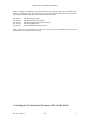
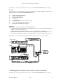
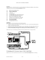
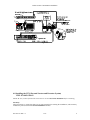
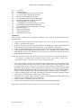
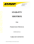
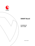
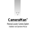
Parkervision™ CameraMan™ Installation
VTEL® Parkervision® CameraMan™
Installation Procedures
INTRODUCTION:
This document is intended to instruct the user on how to install a number of VTEL/Parkervision
CameraMan kit’s. There are a total of five instruction sets for your reference included in this document.
You will choose the correct instruction set based on which VTEL/Parkervision CamerMan kit is being
installed. The operating software on the system is VTEL AppsView™ and Microsoft’s® Windows 95™.
TOOLS NEEDED:
The tools necessary for the installation of any of the five kits are as follows:
1ea. Philips screwdriver (Medium)
1ea. Pencil for a marking instrument
SAFETY WARNINGS:
• Use care when installing or disconnecting cables as they may be broken or pulled loose if mishandled.
• Perform the installation in a clean dry area to avoid any unnecessary injury.
• Follow the shut down procedures before installing any of the kits to avoid unnecessary injury or
damage to the system or components.
SHUTING DOWN THE SYSTEM:
The following steps should be taken before installing any of the five kits to insure that the system is
properly shut down and that the electricity is completely disconnected to avoid personal injury or damage to
the equipment.
Note: If the system is already turned off simply UN-plug the power cord from the wall outlet.
Shutting down AppsView:
• Using the mouse, position the on screen cursor over the “V” in the lower right hand corner of your
monitor and right click by pressing the right mouse button.
• When the dialogue box containing the message “Exit AppsView Immediately” appears on screen select
this and left click. This will shut down the AppsView interface.
• Wait until AppsView has completely shut down as indicated by the appearance of the Windows 95
desktop.
• Move the cursor to the “Start” button of Windows 95 and left click it.
• Move the cursor to the “Shut down” statement of the pop up menu and left click it.
• When the dialogue box appears insure that the statement “Shut down the computer?” is selected, as
indicated by the dot to the left of it. If not move to that spot and left click on it.
• Move the cursor to the button labeled “Yes” and left click to select.
• When the message “It is now safe to turn off your computer” appears on your monitor, shut down the
system using the main power button located inside of the main system cabinet.
• Un-plug the system from the wall outlet.
This concludes the necessary steps to shut down your system safely.
907-818-01 REV A
8/97
1
Parkervision™ CameraMan™ Installation
1.0 General Installation………………………………………………………………..3
2.0 Installing the kits…………………………………………………………………..5
3.0 Installing the VPT (General Pan/Tilt Camera) VTEL P/N 005-1556-05………6
4.0 Installing the VPL (Personal Locator Camera) VTEL P/N 005-1556-02………7
5.0 Installing the VPC (Presenter Camera) VTEL P/N 005-1556-01………….……8
6.0 Installing the VPX (Personal Locator and Presenter System)
VTEL P/N 005-1556-03……………………………………………………….……10
7.0 Installing the VSS (Student System) VTEL P/N 005-1556-04…………………...12
907-818-01 REV A
8/97
2
Parkervision™ CameraMan™ Installation
1.0 General Installation:
This section goes over the general installation instructions for the main camera hardware which will be used
for all kits. Follow these instructions before going on to your specific kit installation instructions.
Inventory:
1ea.
Parkervision CamerMan Camera
1ea.
Monitor mounting bracket
1ea.
Camera mounting bracket
1ea.
¼”-20 screw
2ea.
8-32 Knurled nuts
Installation:
1.
2.
Unpack the camera unit and mounting hardware.
Locate the black mounting bracket marked “CameraMan”. Attach this bracket to the bottom of the
camera using the ¼”-20 screw provided.
NOTE: Be sure the CameraMan and the mounting bracket are aligned as shown in figure 1.1.
Refer to figure 1.2 for orientation and mounting instructions for the camera.
3.
4.
5.
6.
7.
Locate the second bracket marked “Monitor” and orient it so that the studs are facing upward.
Insert the front stud of the “Monitor” bracket into the V-slot of the “CameraMan” bracket.
Slide forward until the two threaded studs at the rear of the “Monitor” mounting bracket engage the
mounting slots of the “CamerMan” mounting bracket.
Secure the union of the two brackets with the knurled nuts provided and tighten.
Place the entire assembly in the desired position on the surface where the camera is to be mounted and
accurately mark the location at the rear of the bracket using a pencil or other marking instrument.
NOTE: Before adhering the mounting bracket to the surface, ensure that the mounting area is free from
dust, oils, or any other material/chemicals which might compromise the adhesive bond.
8.
Remove the “Monitor” mounting bracket from the “CameraMan” mounting bracket by removing the
knurled nuts installed in step 6.
9. Remove the paper liner from the foam adhesive gasket on the bottom of the “Monitor” mounting
bracket.
10. Carefully align the bracket with the location marks previously made.
11. Once aligned, press down firmly over the entire surface to set the adhesive.
12. Allow six hours for curing, before reassembling the mounting brackets.
NOTE: If this is a field upgrade please refer to the “Configuring camera settings” section in the
“Configuring AppsView” chapter of your systems administrator’s guide.
907-818-01 REV A
8/97
3
Parkervision™ CameraMan™ Installation
Figure 1.1
Figure 1.2
2.0 Installing the kits:
907-818-01 REV A
8/97
4
Parkervision™ CameraMan™ Installation
There are multiple kit installation instructions included in this document, locate the part number on the
outside of your shipping crates that corresponds to the camera kit that was purchased with the system. The
following part numbers correspond to the kit instruction that will be used.
005-1556-01
005-1556-02
005-1556-03
005-1556-04
005-1556-05
VPC Kit (Presenter system)
VPL Kit (Personal Locator System)
VPX Kit (Personal Locator/Presenter system)
VSS Kit (Student System)
VPT (General Pan/Tilt Camera System)
Refer to page two of this document to locate the correct page for the installation instruction’s that
corresponds to the system that must be installed.
3.0 Installing the VPT (General Pan/Tilt Camera) VTEL P/N 005-1556-05
907-818-01 REV A
8/97
5
Parkervision™ CameraMan™ Installation
NOTE: Be sure you have followed the instructions in section 1.0 General Installation before continuing.
Inventory:
Take an inventory to ensure that there are no parts missing before starting the installation. (This inventory
includes the parts used in the 1.0 General Installation section).
1ea.
1ea.
1ea.
1ea.
2ea.
1ea.
1ea.
1ea.
Parkervision CamerMan Camera
Monitor mounting bracket
Camera mounting bracket
¼”-20 screw
8-32 Knurled nuts
10’ DB9S-DB9S cable (VTEL P/N 605-1528-01)
12’ S-Video cable (VTEL P/N 605-1444-01)
Parkervision CameraMan Power Supply
Installation:
Refer to figure 3.1 for the interconnection of the following cables.
1. Connect the Camera control cable (P/N 605-1528-01) to the “Aux. A” port on the camera and to the
“Comm. 2” port on the back of the PC.
2. Connect the S-Video cable (P/N 605-1444-01) to the “S-Video Out” port on the camera junction box
(located on the back of the camera) and to the “Camera 1” port on the PC’s expansion box.
3. Connect the CameraMan power supply to the camera junction box (located on the back of the camera).
NOTE: Please refer to the manuals provided for the camera and locator device settings if needed.
Figure 3.1
4.0 Installing the VPL (Personal Locator Camera) VTEL P/N 005-1556-02
NOTE: Be sure you have followed the instructions in section 1.0 General Installation before continuing.
907-818-01 REV A
8/97
6
Parkervision™ CameraMan™ Installation
Inventory:
Take an inventory to ensure that there are no parts missing before starting the installation. (This inventory
includes the parts used in the 1.0 General Installation section).
1ea.
1ea.
1ea.
1ea.
2ea.
1ea.
1ea.
1ea.
1ea.
3ea.
1ea.
1ea.
1ea.
Parkervision CamerMan Camera
Monitor mounting bracket
Camera mounting bracket
¼”-20 screw
8-32 Knurled nuts
10’ DB9S-DB9S cable (VTEL P/N 605-1528-01)
12’ S-Video cable (VTEL P/N 605-1444-01)
Parkervision CameraMan Power Supply
Chairperson Locator Keypad (P/N VCK-2000)
Personal Locator Keypads (P/N VPK-2000)
VPT Operations Manual
VPL Operations Manual
VPL Quick Reference Card
Installation:
Refer to figure 4.1 for the interconnection of the following cables.
1. Connect the Camera control cable (P/N 605-1528-01) to the “Aux. A” port on the camera and to the
“Comm. 2” port on the back of the PC.
2. Connect the S-Video cable (P/N 605-1444-01) to the “S-Video Out” port on the camera junction box
(located on the back of the camera) and to the “Camera 1” port on the PC’s expansion box.
3. Connect the CameraMan power supply to the camera junction box (located on the back of the camera).
NOTE: Please refer to the manuals provided for the camera and locator device settings if needed.
Figure 4.1
5.0 Installing the VPC (Presenter Camera) VTEL P/N 005-1556-01
NOTE: Be sure you have followed the instructions in section 1.0 General Installation before continuing.
907-818-01 REV A
8/97
7
Parkervision™ CameraMan™ Installation
Inventory:
Take an inventory to ensure that there are no parts missing before starting the installation. (This inventory
includes the parts used in the 1.0 General Installation section).
1ea.
1ea.
1ea.
1ea.
2ea.
1ea.
1ea.
1ea.
1ea.
1ea.
1ea.
1ea.
Parkervision CamerMan Camera
Monitor mounting bracket
Camera mounting bracket
¼”-20 screw
8-32 Knurled nuts
10’ DB9S-DB9S cable (VTEL P/N 605-1528-01)
12’ S-Video cable (VTEL P/N 605-1444-01)
120” RCAP-RCAP cable (VTEL P/N 605-774-08)
Parkervision CameraMan Power Supply
Main Docking Station (P/N MDS-2000)
10’ MDS Cable (DB37-DB37)
Tracking Ring Package (P/N TRP-2000)
1ea.
Tracking Power Pack (P/N TPP-2000)
1ea.
Tracking Ring Sensor (P/N TRS-2000)
1ea.
Tracking Ring Belt (P/N TRB-2000)
1ea.
Power Pack Charger (P/N PPC-2000)
25’ CameraMan keypad Cable (P/N CKC-2025)
Tracking System Keypad (P/N TSK-2000)
VPT Operations Manual
VPC Operations Manual
VPC Quick Reference Card
1ea.
1ea.
1ea.
1ea.
1ea.
Installation:
Refer to figure 5.1 for the interconnection of the following cables.
1.
2.
3.
4.
5.
6.
Connect one end of the 10’ MDS (DB37-DB37) cable to the 37 pin Base Unit connector on the back of
the Main Docking Station.
Connect the other end of the 10’ MDS cable to the 37 pin Camera Connection port on the back of the
CameraMan Camera.
Connect one end of the S-Video cable (VTEL P/N 605-1444-01) to the “S-Video Out” port on the back
of the Main Docking Station. Connect the other end of the cable to the “Camera 1” port on the PC
expansion box.
Connect the CameraMan power supply to the Main Docking Station port labeled “DC Power”.
Connect the two antenna (supplied with the MDS) to the Main Docking Station ports labeled “Antenna
1” and “Antenna 2”. (The antenna are interchangeable so order does not matter in this case).
Connect one end of the Camera Control cable (VTEL P/N 605-1528-01) to the “Aux. A” port on the
Main Docking Station. Connect the other end of the cable to the “Comm. 2” port on the back of the PC.
Note: Set the switch labeled “level” on the back of the Main Docking Station to “Line”.
7.
8.
Connect one end of the Audio cable (VTEL P/N 605-774-08) to the “Unbalanced” port on the
back of the Main Docking Station. Connect the other end of the cable to the “Line” input in the
“Microphone” section on the PC expansion box.
Connect the 25’ Keypad cable to the “PVI Comm.” port on the Main Docking Station if using the
keypad in wired mode, otherwise be sure to insert the batteries into the keypad to operate in
wireless mode.
907-818-01 REV A
8/97
8
Parkervision™ CameraMan™ Installation
Figure 5.1
6.0 Installing the VPX (Personal Locator and Presenter System)
VTEL P/N 005-1556-03
NOTE: Be sure you have followed the instructions in section 1.0 General Installation before continuing.
Inventory:
Take an inventory to ensure that there are no parts missing before starting the installation. (This inventory
includes the parts used in the 1.0 General Installation section).
907-818-01 REV A
8/97
9
Parkervision™ CameraMan™ Installation
1ea.
1ea.
1ea.
1ea.
2ea.
1ea.
1ea.
1ea.
1ea.
1ea.
1ea.
1ea.
Parkervision CamerMan Camera
Monitor mounting bracket
Camera mounting bracket
¼”-20 screw
8-32 Knurled nuts
10’ DB9S-DB9S cable (VTEL P/N 605-1528-01)
12’ S-Video cable (VTEL P/N 605-1444-01)
120” RCAP-RCAP cable (VTEL P/N 605-774-08)
Parkervision CameraMan Power Supply
Main Docking Station (P/N MDS-2000)
10’ MDS Cable (DB37-DB37)
Tracking Ring Package (P/N TRP-2000)
1ea.
Tracking Power Pack (P/N TPP-2000)
1ea.
Tracking Ring Sensor (P/N TRS-2000)
1ea.
Tracking Ring Belt (P/N TRB-2000)
1ea.
Power Pack Charger (P/N PPC-2000)
25’ CameraMan keypad Cable (P/N CKC-2025)
Tracking System Keypad (P/N TSK-2000)
Chairperson Locator Keypad (P/N VCK-2000)
Personal Locator Keypads (P/N VPK-2000)
VPT Operations Manual
VPL Operations Manual
VPL Quick Reference Card
VPC Operations Manual
VPC Quick Reference Card
1ea.
1ea.
1ea.
3ea.
1ea.
1ea.
1ea.
1ea.
1ea.
Installation:
Refer to figure 6.1 for the interconnection of the following cables.
1.
2.
3.
4.
5.
6.
Connect one end of the 10’ MDS (DB37-DB37) cable to the 37 pin Base Unit connector on the back of
the Main Docking Station.
Connect the other end of the 10’ MDS cable to the 37 pin Camera Connection port on the back of the
CameraMan camera.
Connect one end of the S-Video cable (VTEL P/N 605-1444-01) to the “S-Video Out” port on the back
of the Main Docking Station. Connect the other end of the cable to the “Camera 1” port on the PC
expansion box.
Connect the CameraMan power supply to the Main Docking Station port labeled “DC Power”.
Connect the two antenna (supplied with the MDS) to the Main Docking Station ports labeled “Antenna
1” and “Antenna 2”. (The antenna are interchangeable so order does not matter in this case).
Connect one end of the Camera Control Cable (VTEL P/N 605-1528-01) to the “Aux. A” port on the
Main Docking Station. Connect the other end of the cable to the “Comm. 2” port on the back of the PC.
Note: Set the switch labeled “level” on the back of the Main Docking Station to “Line”.
7.
8.
Connect one end of the Audio cable (VTEL P/N 605-774-08) to the “Unbalanced” port on the
back of the Main Docking Station. Connect the other end of the cable to the “Line” input in the
“Microphone” section on the PC expansion box.
Connect the 25’ Keypad cable to the “PVI Comm.” port on the Main Docking Station if using the
keypad in wired mode, otherwise be sure to insert the batteries into the keypad to operate in
wireless mode.
907-818-01 REV A
8/97
10
Parkervision™ CameraMan™ Installation
Figure 6.1
7.0 Installing the VSS (Student System) VTEL P/N 005-1556-04
NOTE: Be sure you have followed the instructions in section 1.0 General Installation before continuing.
Inventory:
Take an inventory to ensure that there are no parts missing before starting the installation. (This inventory
includes the parts used in the 1.0 General Installation section).
1ea.
1ea.
1ea.
Parkervision CamerMan Camera
Monitor mounting bracket
Camera mounting bracket
907-818-01 REV A
8/97
11
Parkervision™ CameraMan™ Installation
1ea.
2ea.
1ea.
1ea.
1ea.
1ea.
1ea.
1ea.
1ea.
1ea.
1ea.
1ea.
1ea.
1ea.
1ea.
¼”-20 screw
8-32 Knurled nuts
10’ DB9S-DB9S cable (VTEL P/N 605-1528-01)
12’ S-Video cable (VTEL P/N 605-1444-01)
Parkervision CameraMan Power Supply
25’ CameraMan keypad Cable (P/N CKC-2025)
Classroom controller Keypad (P/N CCK-2000)
CameraMan RS-485 “T” Connector.
3’ CameraMan Communications Cable (CCC-2003)
Programmable Response Module (PRM-2000)
10’ CameraMan Communications Cable (CCC-2010)
PRM Power Supply
VPT Operations Manual
VSS Operations Manual
VSS Quick Reference Card
Installation:
Refer to figure 7.1 (Single mixer set up) and 7.2 (Multiple mixer set up) for the interconnection of the
following cables.
1.
2.
3.
4.
Connect the Camera Control cable (P/N 605-1528-01) to the “Aux. A” port on the camera and to the
“Comm. 2” port on the back of the PC.
Connect the S-Video cable (P/N 605-1444-01) to the “S-Video Out” port on the camera junction box
(located on the back of the camera) and to the “Camera 1” port on the PC’s expansion box.
Connect the CameraMan power supply to the camera junction box (located on the back of the camera).
Connect the RS-485 CameraMan Communications cable (3’ or 10’ depending upon the distance of the
PRM from the Camera) to the “RS-485” port on the back of the camera to the “RS-485” port on the
Programmable Response Module.
NOTE: This installation will more than likely include the optional microphones and mixer and therefore
these options are included in these installation instructions. Refer to the manuals, cut sheets, and
microphone installation/specification sheet (comes with microphone kit).
5.
6.
7.
8.
9.
Connect the microphone’s (VTEL P/N 600-2085-01) cable to the optional “Y” cable (VTEL P/N 6051511) or adapter cable (VTEL P/N 605-1510). If the adapter cable is used, simply connect these cables
to the XLR inputs on the mixer. If the “Y” cables are used connect the XLR connectors to the
microphone inputs on the mixer and the green Phoenix™ connectors to the corresponding inputs on the
PRM. (Microphone and PRM inputs must correspond to operate correctly e.g. If the XLR is connected
to input 1 on the mixer than the green phoenix connector must be connected to input 1 on the PRM.
Connect the supplied mixer cable (VTEL P/N 600-264) to the mixer port labeled “Main Out” and the
other end to the “Microphone Line” input on the PC expansion box.
If using the “Gate” with the “Mixer” connect the “Patch” cables (Supplied) from each “Patch” port on
the gate to the corresponding “In/Out” port on the mixer.
Connect “DC Out” on the Mixer to “DC In” on the Gate.
Connect the power supplies to the Mixer and to the Programmable Response Module.
NOTE: Refer to the supplied manuals and cut sheets for operation and setting information.
907-818-01 REV A
8/97
12
Parkervision™ CameraMan™ Installation
Figure 7.1
907-818-01 REV A
8/97
13
Parkervision™ CameraMan™ Installation
Figure 7.2
907-818-01 REV A
8/97
14