
1
TREADMILLS – USER MANUAL TABLE OF CONTENTS 1! INTRODUCTION ................................................................................................ 4! 1.1! PRODUCT WARRANTY ....................................................................................................... 4! 1.2! BODYGUARD FITNESS CONTACT INFORMATION .......................................................... 4! 2! IMPORTANT SAFETY INSTRUCTIONS ........................................................... 5! 2.1! 2.2! 2.3! 2.4! GROUNDING INSTRUCTIONS ............................................................................................ 8! RADIO FREQUENCY INTERFERENCE (RFI) ..................................................................... 9! STATIC ELECTRICITY ....................................................................................................... 10! USING THE EMERGENCY STOP SYSTEM ...................................................................... 11! 3! GETTING TO KNOW YOUR TREADMILL ...................................................... 12! 3.1! MAIN FRAME COMPONENTS ........................................................................................... 12! 3.2! CONSOLE OVERVIEW ...................................................................................................... 13! 3.3! CONSOLE (T-30) ................................................................................................................ 14! 3.4! CONSOLE (T-45 & T-75) .................................................................................................... 14! 3.5! MAIN KEYPAD (T-30 & T-45) ............................................................................................. 16! 3.6! MAIN KEYPAD (T-75) ......................................................................................................... 16! 3.7! CONSOLE FEATURES ...................................................................................................... 17! 3.8! WORKOUT PARAMETERS ............................................................................................... 20! 3.9! PARAMETERS GLOSSARY .............................................................................................. 21! 3.10!MEASURING YOUR HEART RATE ................................................................................... 22! 3.11!MAXIMUM HEART RATE (MHR) ....................................................................................... 23! 4! EXERCISE PROGRAMS ................................................................................. 24! 4.1! PROGRAM CATEGORY GRID .......................................................................................... 24! 4.2! PROGRAM SETUP ............................................................................................................ 25! 4.3! JUSTGO PROGRAM .......................................................................................................... 26! 4.4! MANUAL (TIME GOAL) PROGRAM .................................................................................. 26! 4.5! CALORIE GOAL PROGRAM .............................................................................................. 26! 4.6! DISTANCE GOAL PROGRAM ........................................................................................... 26! 4.7! INTERVAL PROGRAM ....................................................................................................... 26! 4.8! RANDOM PROGRAM ........................................................................................................ 27! 4.9! WALK PROGRAM .............................................................................................................. 27! 4.10!SPEED RUN PROGRAM ................................................................................................... 28! 4.11!HILL CLIMB PROGRAM ..................................................................................................... 28! 4.12!HEART RATE CONTROL PROGRAM ............................................................................... 28! 4.13!HEART RATE INTERVAL PROGRAM ............................................................................... 29! 4.14!FITNESS TEST ................................................................................................................... 30! 4.15!CARDIOVASCULAR PROGRAM ....................................................................................... 31! 4.16!ADVANCED HILLS PROGRAM ......................................................................................... 32! 4.17!TRACK PROGRAM ............................................................................................................ 32! 4.18!RUNNER’S INTERVALS PROGRAM ................................................................................. 32! 4.19!TURBO TRAINING PROGRAM .......................................................................................... 33! 1 TREADMILLS – USER MANUAL 4.20!CUSTOM PROGRAMS ...................................................................................................... 33! 4.21!MEMORY PROGRAMS ...................................................................................................... 34! 5! SETTINGS MENU ............................................................................................ 35! 5.1! 5.2! 5.3! 5.4! 5.5! ACCESSING THE SETTINGS MENU ................................................................................ 35! LANGUAGE ........................................................................................................................ 36! WEIGHT UNIT .................................................................................................................... 36! DISTANCE UNIT ................................................................................................................ 36! USER IDENTIFICATION .................................................................................................... 36! 5.5.1! CREATE&USER&................................................................................................................................................................................&36! 5.5.2! EDIT&USER&.......................................................................................................................................................................................&36! 5.5.3! DELETE&USER&................................................................................................................................................................................&36! 5.5.4! TURN&USER&ID&OFF&.....................................................................................................................................................................&37! 5.6! STATS ................................................................................................................................ 37! 5.6.1! VIEW&STATISTICS&........................................................................................................................................................................&37! 5.6.2! RESET&STATISTICS&......................................................................................................................................................................&37! 5.7! CONSOLE LOCK ................................................................................................................ 37! 5.8! WARM UP ........................................................................................................................... 37! 5.9! COOL DOWN ..................................................................................................................... 38! 5.10!SPEED LIMITS ................................................................................................................... 38! 5.11!INCLINE LIMITS ................................................................................................................. 38! 5.12!PAUSE TIME ...................................................................................................................... 38! 5.13!BIG NUMBER OPTION ...................................................................................................... 38! 5.14!CUSTOM PROGRAM ......................................................................................................... 39! 5.15!MEMORY OPTION ............................................................................................................. 39! 5.16!CLOCK OPTION ................................................................................................................. 39! 5.17!SOUND OPTION ................................................................................................................ 40! 5.18!AUTO POWER OFF ........................................................................................................... 40! 5.19!TURBO TRAINING ............................................................................................................. 40! 5.20!DEFAULT USER WEIGHT ................................................................................................. 40! 6! DIAGNOSTICS MENU ..................................................................................... 41! 6.1! ACCESSING THE DIAGNOSTICS MENU ......................................................................... 41! 6.2! NVRAM TEST ..................................................................................................................... 42! 6.3! KEYPAD TEST ................................................................................................................... 42! 6.4! DISPLAY TEST ................................................................................................................... 42! 6.5! BEEPER TEST ................................................................................................................... 43! 6.6! HEART RATE TEST ........................................................................................................... 43! 6.7! SAFETY KEY TEST ............................................................................................................ 43! 6.8! BELT ALIGNMENT TEST (PROCEDURE) ........................................................................ 43! 6.9! INCLINE CALIBRATION ..................................................................................................... 43! 6.10!MOTOR CHECK (DRIVE MOTOR TEST) .......................................................................... 44! 6.11!CURRENT TEST ................................................................................................................ 44! 6.12!ESC TEST .......................................................................................................................... 44! 6.13!SPEED SENSOR TEST ..................................................................................................... 45! 6.14!ERROR LOG ...................................................................................................................... 45! 6.15!MAINTENANCE .................................................................................................................. 45! 2 TREADMILLS – USER MANUAL 6.16!STATISTICS ....................................................................................................................... 46! 6.17!USB TEST .......................................................................................................................... 46! 6.18!EXTREME AMPERAGE (ERROR 60) ................................................................................ 47! 7! GENERAL MAINTENANCE............................................................................. 48! 7.1! 7.2! 7.3! 7.4! 7.5! 7.6! GENERAL MAINTANCE TIMETABLE ................................................................................ 48! DRIVE BELT TENSION CHECK ........................................................................................ 49! DRIVE BELT ALIGNMENT ................................................................................................. 49! WALKING BELT TENSION CHECK ................................................................................... 50! WALKING BELT ALIGNMENT ........................................................................................... 50! DECK & WALKING BELT CONDITION CHECK ................................................................ 52! 7.6.1! OVERVIEW&......................................................................................................................................................................................&52! 7.6.2! STAGES&OF&DECK&&&WALKING&BELT&WEAR&....................................................................................................................&52! 7.6.3! PERFORMING&A&CURRENT&TEST&..........................................................................................................................................&52! 7.6.4! AVERAGE&ERAGE&................................................................................................................................................................&53! 7.7! DECK AND WALKING BELT CLEANING AND LUBRICATION ......................................... 53! 7.8! CHANGING A WALKING BELT .......................................................................................... 55! 7.9! ROTATING OR FLIPPING A DECK ................................................................................... 56! 7.10!UPDATING SOFTWARE .................................................................................................... 56! 8! TROUBLESHOOTING PROBLEMS ................................................................ 57! 8.1! MAINTENANCE WARNINGS (AFDS) ................................................................................ 57! 8.2! WALKING BELT PROBLEMS ............................................................................................ 58! 8.3! COMMON NOISES ............................................................................................................. 59! 8.3.1! CLICKING&NOISES&........................................................................................................................................................................&59! 8.3.2! RUBBING,&SCRAPING,&SQUEAKING&OR&POPPING&NOISES&..........................................................................................&60! 8.3.3! LOUD&KNOCKING/RATTLING/VIBRATION&NOISES&.....................................................................................................&61! 8.4! MOTOR CONTROL BOARD (M.C.B.) OPERATIONAL CODES ....................................... 63! 8.5! DISPLAY ERROR CODES ................................................................................................. 65! 8.5.1! ERROR&51&........................................................................................................................................................................................&65! 8.5.2! ERROR&52&........................................................................................................................................................................................&65! 8.5.3! ERROR&53&........................................................................................................................................................................................&66! 8.5.4! ERROR&54&........................................................................................................................................................................................&67! 8.5.5! ERROR&55&........................................................................................................................................................................................&67! 8.5.6! ERROR&56&........................................................................................................................................................................................&67! 8.5.7! ERROR&57&........................................................................................................................................................................................&67! 8.5.8! ERROR&60&........................................................................................................................................................................................&67! 8.5.9! ERROR&100&......................................................................................................................................................................................&67! 8.6! HEART RATE MONITORING ............................................................................................. 68! 8.6.1! CONTACT&HEART&RATE&SYSTEM&..........................................................................................................................................&68! 8.6.2! WIRELESS&HEART&RATE&SYSTEM&........................................................................................................................................&69! 3 TREADMILLS – USER MANUAL 1 INTRODUCTION Bodyguard Fitness is dedicated to designing and manufacturing the very best performing fitness equipment on the market. This manual outlines the operational information, safety precautions, basic maintenance requirements and service guidelines for your piece of Bodyguard Fitness equipment. To ensure that you get the maximum benefit from your equipment, we recommend that you read this manual carefully before attempting to assemble and use your treadmill. If you require service for your equipment, be prepared to provide your machine’s 10-digit serial number. You will find the 10-digit serial number printed on a plate that is attached to the frame of the unit as well as on the Warranty Registration Card. Please fill out the grid below so the information is easily accessible if required in the future. Product Name (e.g. T75 Treadmill) Model Number (F16652750) 10-Digit Serial Number Date of Purchase Dealer Store Name Dealer Phone Number 1.1 PRODUCT WARRANTY It is important that you register your purchase with Bodyguard Fitness within 30 days of the purchase date so your product’s warranty is activated. Product warranties are not transferrable so to avoid delays if warrantied service is required please register your product immediately at www.bodyguardfitness.com by clicking on “Customer Service” in the top menu then “Warranty Registration” and completing the online form. Alternatively, you may fill out the warranty registration card that came with your unit and mail it to the address on the card. IMPORTANT – If you omit to send your warranty card to Bodyguard Fitness or register online within 30 days of the date of purchase then you will be required to send Bodyguard Fitness proof of purchase before receiving any warrantied parts or service. The product warranty is described in detail on the product warranty sheet found in your documentation package. You may also see a complete copy of this document at www.bodyguardfitness.com Read the product warranty information carefully and note the information covering wear items and the owner’s responsibilities to general maintenance. 1.2 BODYGUARD FITNESS CONTACT INFORMATION Bodyguard Fitness 9095, 25th Avenue Saint-Georges, Quebec, Canada, G6A-1A1 Customer Service: Sales: General Information: 4 1-888-407-3784 1-800-373-2639 1-418-228-8934 [email protected] [email protected] [email protected] TREADMILLS – USER MANUAL 2 IMPORTANT SAFETY INSTRUCTIONS To ensure that you get the maximum benefit from your equipment, we recommend that you read this manual carefully before attempting to assemble and use your treadmill. Save this document and refer back to it if you are unfamiliar with the operation of the machine. Use of this equipment by people with heart or other medical problems may result in serious injury. Consult your physician before using this equipment, and continue to do so periodically as you continue to use this equipment. Cease exercising immediately if you feel dizzy, faint or shortness of breath. Using this equipment improperly or in a manner other than that prescribed in this manual may result in serious injury. This appliance is not intended for use by persons (including children) with reduced physical, sensory or mental capabilities, or lack of experience and knowledge, unless they have been given supervision or instruction concerning use of the appliance by a person responsible for their safety. DANGER: To reduce the risk of electrical shock, always unplug this Bodyguard Fitness product before cleaning or attempting any maintenance activity. CAUTION – This treadmill should be plugged into a dedicated 15 amps circuit in order to avoid functional problems. Do not use any adaptors or power bars. If an extension cord is necessary ensure it is at least 14 gauge or thicker. Always use a properly grounded and polarized 3-pronged AC outlet. See Grounding Instructions section 2.1. WARNING – To prevent the risk of fire or electrical shock, do not expose this machine to rain or moisture. Do not install the machine outdoors or near swimming pools, sauna rooms or high humidity environments. Ensure the room temperature is between 15°C & 35°C and the humidity is between 30% and 70%. Using your equipment in conditions outside this range may affect some functionalities and/or your warranty. Any changes or modifications to this equipment could void the product warranty. Refer servicing to qualified Bodyguard Service personnel only. If you have any questions about the assembly, proper use or repair of your treadmill, please contact Bodyguard Fitness Customer Service. An Authorized Bodyguard Fitness Dealer must make any necessary repairs during the warranty period. 5 TREADMILLS – USER MANUAL WARNING - TO REDUCE THE RISK OF BURNS, FIRE, ELECTRIC SHOCK OR INJURY: 6 • Maintain a clear space behind the treadmill of at least 2 metres (78 inches) and to the front and sides of the treadmill of at least 1 metre (39 inches). Do not box in the equipment or place it up against walls, furniture or obstacles and avoid the possibility of bystanders making contact with the user or the equipment. Place the equipment in such a way that the power can be easily disconnected. • Always install the equipment on a stable base and ensure it is properly leveled. • Never leave a plugged in treadmill unattended. • Keep the power cord away from all moving parts of the treadmill, such as the incline arm and front transport wheels. Do not run the power cord under or along the side the treadmill. Do not use any power cord that is damaged or has been pinched or even partially immersed in water; contact your service provider or the manufacturer to have it replaced. • Do not allow use of the equipment by unsupervised children or persons with reduced physical, sensory or mental capabilities, or people lacking experience or knowledge of the equipment. • Keep the safety key in a secure place, out of the reach of children. • Do not use attachments not recommended by the manufacturer. • Never operate the equipment with the air openings blocked. Keep the air openings free of obstructions such as lint and hair. TREADMILLS – USER MANUAL 7 • Never drop or insert any object into any opening. If an object should drop inside, turn off the power, unplug the power cord from the outlet and carefully retrieve it. If the item cannot be reached contact Bodyguard Fitness customer support. • Do not operate where aerosol (spray) products are being used or where oxygen is being administered. Such substances create the danger of combustion and explosion. • Do not place liquids of any type on or near the unit, except in a bottle holder or accessory tray. Securely lidded containers are recommended. • Do not exceed the maximum user weight as outlined in the product specifications. • Allow only one person at a time on the treadmill. • Do not allow animals on or near the treadmill. • Wear proper exercise footwear when using the treadmill. Do not use the treadmill in bare feet or in socks. It is normal for the treadmill belt to dislodge soil or pebbles lodged in the soles of your shoes so it is recommended to clean the soles of your shoes before using the treadmill. • Keep all loose clothing, shoelaces, towels or other loose materials away from moving parts. • Always use the handrails when stepping on and off the treadmill or when any extra stability is required. In case of emergency such as tripping, the side handrails should be grabbed and the user should place their feet on the side rails. The front handlebars should be used to grasp the heart rate sensors or to stabilize the user when pressing the console buttons but are not for continuous use. • Always attach the safety clip to your clothing before starting the treadmill and ensure the safety key is correctly placed on the console. • Always stand on the foot rails, not the walking belt, when starting the treadmill. • Always ensure the belt is centered before starting the treadmill. If the belt has drifted to one side, adjust it per the instructions in the General Maintenance section before exercising. • Never walk, jog or run backwards on the treadmill. • Never try to accelerate or decelerate the speed of the walking belt by pushing on it or trying to stop it, with or without power. • Never reach into or underneath the equipment or tip it on its side during operation. • Do not allow other people to interfere with the user or equipment during a workout. • Always wait for the belt to come to a complete stop before stepping off the treadmill. • Always unplug this appliance from the electrical outlet immediately after use and prior to any maintenance or cleaning. • When disconnecting the power, always turn the power switch off first then gently remove the plug from the wall outlet. Do not pull the power cord by the cable. • Allow only trained personnel to service this equipment. • When moving the treadmill lift from the back frame and never from the console. TREADMILLS – USER MANUAL 2.1 GROUNDING INSTRUCTIONS This product must be correctly grounded. If it should malfunction or break down, grounding provides a path of least resistance for electric current to reduce the risk of electric shock. This product is equipped with a cord having an equipment-grounding conductor and a grounding plug. The plug must be plugged into an appropriate outlet that is properly installed and grounded in accordance with all local codes and ordinances. Failure to properly ground the equipment could void the product’s warranty. DANGER – Improper connection of the equipment-grounding conductor can result in a risk of electric shock. Check with a qualified electrician or serviceman if you are in doubt as to whether the product is properly grounded. Do not modify the plug provided with the product – if it does not fit the outlet, have a proper outlet installed by a qualified electrician. 120VAC Units Designated for North American Markets The unit must be connected to a dedicated, grounded circuit. A 15 amp dedicated circuit is required, but a 20 amp dedicated circuit is recommended. The power outlet must have the same configuration as the plug. No adapter should be used with this product. 8 TREADMILLS – USER MANUAL 2.2 RADIO FREQUENCY INTERFERENCE (RFI) Federal Communications Commission, Part 15 This fitness equipment has been tested and found to comply with the limits for a Class B digital device, pursuant to Part 15 of the FCC Rules. These limits are designed to provide reasonable protection against harmful interference in a residential installation. The equipment generates, uses, and can radiate radio frequency energy and, if not installed and used in accordance with the owner’s manual instructions, may cause harmful interference to radio communications. If the equipment does cause harmful interference to radio or television reception, which can be determined by turning the unit off and on, you are encouraged to try to correct the interference using one or more of the following measures: • Reorient or relocate the receiving antenna for your TV, radio, VCR, DVR, etc. • Increase separation between the unit and the receiver (TV, radio, etc.). • Connect the equipment into a different power outlet on a dedicated circuit different from the one used by the receiver (TV, radio, etc.). No other appliance should be plugged into the same power outlet as the equipment. • Consult an experienced radio/TV technician for help. WARNING - Per FCC rules, changes or modifications not expressly approved by Bodyguard could void the user’s authority to operate the equipment. Canadian Department of Communications This digital apparatus does not exceed the Class B limits for radio noise emissions from digital apparatus set out in the Radio Interference Regulations of the Canadian Department of Communications. 9 TREADMILLS – USER MANUAL 2.3 STATIC ELECTRICITY Treadmills are powerful machines that can generate static electricity, causing some users to receive a shock. In excess amounts, static electricity can damage the treadmill's electronic components. There are simple steps you can take to reduce the risk of being shocked by your treadmill. If you are unable to troubleshoot the problem successfully, have the machine professionally serviced. Environmental Causes Static electricity can be generated by a number of environmental causes. Producing static electricity is common when using a treadmill due to the friction created by repetitive motion. A treadmill placed directly on non-treated carpet may be more susceptible to static electricity. Dry, dusty environments can magnify the presence and intensity of static electricity. Treadmills that are not cleaned regularly can suffer from a buildup of dirt, increasing your risk of being shocked. Mechanical Causes The treadmill motor can become clogged with dust and other debris, increasing the risk of static electricity. Increased friction from a worn-out belt can also generate static electricity. Inspect the power cord and plug for damage. Failing to plug your treadmill into a grounded outlet equipped with a surge protector can also increase your risk of being shocked. Simple Ways to Reduce Static In dry climates, place a humidifier in the treadmill room to help reduce static electricity. A humidity level of 45 percent is recommended. Place a rubber mat underneath your machine to reduce the amount of debris that can build up in the treadmill's motor. Use fabric softener or anti-static spray to protect a treadmill used on a carpeted surface. Wear clothing made of natural materials, like cotton, as synthetic materials, like polyester and nylon, are more prone to static cling. Choose shoes constructed of nonconductive materials and clean them before using your treadmill. Treadmill Maintenance Tips Keeping your treadmill clean and lubricated can also help reduce the risk of shocks from static electricity. Refer to the General Maintenance section of this owner’s manual for more information on maintaining your treadmill. If limiting static electricity does not reduce the incidence of shocking, cease use of the machine and have your treadmill evaluated and serviced by an experienced professional. 10 TREADMILLS – USER MANUAL 2.4 USING THE EMERGENCY STOP SYSTEM This treadmill is equipped with an emergency stop system comprising of a clip tied to a safety key that slots into a safety switch inside the console. When the clip is pulled the safety key is removed from the its slot in the console, opening the safety switch which will stop the walking belt and place the console into a pause mode for the countdown duration displayed on the screen. Before starting your workout, test that this system works correctly by following the steps below. Step onto the treadmill’s foot rails. Attach the clip to your clothing and make sure the safety key is located in its correct slot on the console. Press the JUSTGO button. If the emergency stop system is functioning correctly a 3, 2, 1 countdown will begin and the treadmill belt will start to move at 0.5mph or km/h. Grip the handrails and carefully step onto the belt and begin walking making sure you are located in the middle of the workout area. Stop walking and let the belt slowly take you to the back of the treadmill belt area. As you approach the rear of the treadmill the range of the clip cord will be maxed out and will pull and remove the safety key from its location on the console causing the walking belt to stop. If you feel the distance is too long before the safety key is removed, you may reduce the length of the cord. IMPORTANT: For your safety, DO NOT LENGTHEN the cord under any circumstances. Always use the emergency stop system when exercising on the treadmill. If the safety key is removed while you are exercising, the walking belt will come to a stop and the treadmill will enter into a PAUSE mode. You will need to place back the safety key into its correct position and press the JUSTGO key to resume the workout. 11 TREADMILLS – USER MANUAL 3 GETTING TO KNOW YOUR TREADMILL 3.1 MAIN FRAME COMPONENTS T-30 model shown 12 TREADMILLS – USER MANUAL 3.2 CONSOLE OVERVIEW The table below compares the main features of the different consoles. T-30 T-45 T-75 Display Type 5 Window Red L.E.D. Blue L.C.D. Blue LCD & White L.E.D. Parameters Displayed Incline Range 9 0.5 - 12mph 0.8 - 19.2 km/h 0% - 15% 23 0.5 - 12mph 0.8 - 19.2 km/h 0% - 15% 23 0.5 - 12mph 0.8 - 19.2 km/h -3% - 15% Standard Programs 7 15 15 Custom Programs - 8 8 Memory Programs - 8 8 Heart Rate Contact & Wireless Contact & Wireless Contact & Wireless Main Keypad Position Below Display Below Display Front Handlebar User ID’s - Quick Keys - Preset Speed Keys - 8 Speed, Elevation, Program & User 2 8 Speed, Elevation, Program & User 2 iTEK Basic Advanced Advanced USB Port - Yes Yes iPad Bluetooth Connect - Optional Optional Speed Range 13 TREADMILLS – USER MANUAL 3.3 CONSOLE (T-30) The T-30 console features 5 Red L.E.D. Data Windows that show the parameters of the exercise under way as well as a clear program list and a convenient reading rack/device holder. T-30 Console 3.4 CONSOLE (T-45 & T-75) The T-45 and T-75 consoles feature a 20 x 13 block profile surrounded by information windows showing the parameters of the exercise under way and a 16 character alphanumeric message center at the bottom of the screen that scrolls information during and after a workout. They also include a range of advanced user functions as well as a convenient reading rack/device holder. The vertical axes of the profile show either speed or incline values. A graduated bar on the right of the profile means the speed profile is on display. If the graduated bar is on the left side of the profile then the incline profile is on display. A matrix of 20 horizontal segments and 13 vertical levels is displayed in the center of the screen. Horizontally, each segment (block) represents one twentieth of the length of the exercise. Vertically, each line represents a speed increment of approximately 1mph or 1.5 km/h, and an incline increment of 1.5%. Every exercise program begins with a flashing block on the left-hand side of the screen and ends when it has reached the right-hand side of the screen. As the speed and incline increase, the profile moves towards the top of the screen. At the bottom of the screen, an alphanumeric message center displays various exercise parameters not shown in the dedicated windows. 14 TREADMILLS – USER MANUAL T-45 Console T-75 Console 15 TREADMILLS – USER MANUAL 3.5 MAIN KEYPAD (T-30 & T-45) The T-30 & T-45 MAIN KEYPAD has 8 silicone keys. From left to right these keys are: INCREASE INCLINE (BLUETOOTH ON/OFF) DECREASE INCLINE, iTEK (HOME), COOL DOWN, STOP (PAUSE), JUSTGO (ENTER), INCREASE SPEED and DECREASE SPEED. 3.6 MAIN KEYPAD (T-75) The T-75 MAIN KEYPAD is situated on the front handlebar and has 7 silicone keys. From left to right these keys are; INCREASE INCLINE (BLUETOOTH ON/OFF), DECREASE INCLINE, iTEK (HOME), STOP (PAUSE), JUSTGO (ENTER), INCREASE SPEED and DECREASE SPEED. Note that on the T75, the COOL DOWN feature does not have a designated button and must be programmed automatically in the Settings Menu. 16 TREADMILLS – USER MANUAL 3.7 CONSOLE FEATURES ALPHANUMERIC MESSAGE CENTER Situated below the profile the 16-character alphanumeric message center shows menu information, workout parameters during and after a workout as well as maintenance and error data when necessary. BLUETOOTH ON/OFF (optional on T-45 & T-75 only) When at the HOME SCREEN on compatible products the INCREASE INCLINE key acts a Bluetooth Connecting Toggle Switch. Pressing it once will turn the Bluetooth Connecting Feature on (BLUETOOTH ON displays on screen) at which point it will search for a device to connect or pair with before automatically turning off after 30 seconds (BLUETOOTH OFF displays on screen). Pressing the INCREASE INCLINE key a second time before the 30 seconds has passed will turn the Bluetooth Connecting feature off. COOL DOWN KEY (T-30 & T-45 only) Press this key to begin a cool-down period on compatible programs. (see section 5.9) INCREASE/DECREASE INCLINE KEYS Pressing these keys allows you to modify the angle of the walking belt during the exercise. If you continuously hold down a key, the incline display will gradually change (0.5% at a time). Release the key when you have selected your desired exercise incline. The incline of the treadmill will slowly change. On the display, the desired incline will flash until it has been attained. These keys also allow you to select the parameters prior to each exercise and act as scrolling keys in various menus. THE INCREASE INCLINE key also toggles the BLUETOOTH Transmission ON/OFF when at the HOME SCREEN. INCREASE/DECREASE SPEED KEYS Pressing these keys allows you to modify the speed of the walking belt during the exercise. If you continuously hold down a key, the speed display will gradually change (0.1 km/h or 0.1 mph at a time). Release the key when you have selected your desired exercise speed. The treadmill belt will slowly change to reach the speed you want. On the display, the desired speed will flash until it has been attained. These keys also allow you to select the programs and parameters prior to each exercise and act as scrolling keys in various menus. iTEK (HOME) KEY This key has different functions depending on the unit and operational stage of the equipment. On all models, when at the HOME SCREEN; Press the iTEK key once to access the SETTINGS MENU (see section 5.1). Press and hold the iTEK key for 3 seconds to access the DIAGNOSTICS MENU (see section 6.1) On a T-45 & T-75, when in a general menu; Pressing the iTEK key acts as a Home Key and cancels all data and returns to the HOME SCREEN. On a T-45 & T-75, during a workout; Press the iTEK key to scroll through various equipment performance statistics. • CURRENT (XX.X): Shows the current (DC amps) at the drive motor. • AVERAGE CURRENT (XX.X): Shows the rolling average current (DC amps) at the drive motor over the previous hours of operation based on an algorithm. • TOTAL DISTANCE (XXX.X): Like an odometer in a car, it shows the total distance (miles/km) covered by the treadmill prior to the current workout. Note, this data is stored on a memory chip on the upper board so if the upper board is changed the numbers will be reset. • TOTAL TIME (XX MONTHS, XX DAYS, XX HOURS, XX MINUTES, XX SECONDS): Shows the total time of use of the treadmill prior to the current workout. This is used to calculate average 17 TREADMILLS – USER MANUAL use per day statistics for commercial warranty purposes. Note, this data is stored on a memory chip on the upper board so if the upper board is changed the numbers will be reset. JUSTGO (ENTER) KEY This key has different functions depending on the unit and operational stage of the equipment. On all models, when at the HOME SCREEN; Press the green JUSTGO key to start a JustGo workout without inputting any parameters. On all models, when the 3, 2, 1 workout countdown is in action: Press the JUSTGO key to skip the countdown and begin the program. On all models, when using the menu systems; Press the ENTER key to select a menu and save data. On a T-45 & T-75, during a workout; Press the JUSTGO key to change the profile on display. (See Profile Display below) MAIN KEYPAD The Main Keypad is a group of the most used operational keys. The keys on the Main Keypad are made of silicone, as it is a more durable material able to withstand heavy use. PRESET SPEED KEYS - A & B (T-45 & T-75 only) These keys are similar to the Quick Speed Keys in that they allow you to quickly change the walking belt speed. However, as opposed to the Quick Speed Keys, whose values cannot be changed, the Preset Speed Keys are customizable, allowing you to store any speed value (e.g. 3.6) and changing it anytime you like. This is especially interesting for users who wish to alternate between two preset speeds (such as in Manual Interval training) and eliminates the annoyance of having to hold down or repeatedly press the Increase/Decrease Speed buttons mid-exercise when trying to reach a target speed. To store a speed value to a Preset Speed Key, simply run the treadmill at the desired speed and then press and hold down the Preset Speed Keys for 1 second until you hear a beep. If a User ID is selected while completing this process, the value will be saved to that User ID to use the next time they log in. If there is no User ID selected, the values will be cleared from the memory after the workout ends. When a Preset Speed key is pressed during exercise, the words CONFIRM = JUSTGO will appear on the screen as a safety precaution. At that point the ENTER key must be pressed to confirm the selection. PROFILE DISPLAY (T-45 & T-75 only): During a workout, you can change the profile being displayed from a speed graphic profile (default) to an incline graphic profile by pressing the JUSTGO key. To have the speed and incline profiles alternate continuously, press and hold the JUSTGO key for 3 seconds when the workout parameters are scrolling in the alphanumeric screen (not when iTek stats are scrolling). To return to speed or incline mode, press the JUSTGO key one more time. PROGRAM CATEGORY KEYS (T-45 & T-75 only): These 3 keys allow you to quickly access the program category of your choice. From left to right the 1st button leads you to a series of Basic Programs; the 2nd leads you to the Cardio Programs (Programs that require a heart rate chest strap) and the 3rd key on the right leads you to Advanced Programs which include the Memory and Custom Programs. Once a program category key is pressed you will see the first program in that program category’s list and to scroll though the list you may press the same category key again or the INCREASE/DECREASE SPEED or INCLINE keys. See the Program Category grid in section 4.1 for more information on the programs under each category. 18 TREADMILLS – USER MANUAL QUICK INCLINE KEYS (T-45 & T-75 only): These keys allow you to quickly modify the incline of the platform during an exercise to a preset value without having to use the INCREASE/DECREASE INCLINE keys. QUICK SPEED KEYS (T-45 & T-75 only): These keys allow you to quickly modify the speed of the walking belt during an exercise without having to use the INCREASE/DECREASE SPEED keys. Once a quick speed button has been pressed the ENTER key must be pressed to confirm the selection. READING RACK & DEVICE HOLDER Designed to safely hold most magazines, small books and devices such as mobile phones, music players and tablets. SAFETY KEY: The safety key must be inserted into the appropriate slot in the console for the treadmill to be functional. For security purposes, make sure to attach the safety key clip to your clothes prior to starting an exercise. See section 2.4 for more information about the Emergency Stop System. STATS KEY (T-45 & T-75 only): Each User ID saves cumulative statistics to their personal data file. The STATS key allows the current User ID to view their total cumulative statistics from the HOME SCREEN. If no User ID has been selected the key will be inactive. STOP (PAUSE) KEY: This key has different functions depending on the unit and operational stage of the equipment. On all models, when using the menu systems; Press the STOP key to go back in the menu system or cancel a function. On all models, during a workout; Press the red STOP key to bring the walking belt to a stop and place the program into a pause mode. Press the STOP key again during the PAUSE mode to end the current program and the treadmill will be reset. On the T-45 & T-75, the final stats for the completed workout will scroll across the screen. USB PORT (T-45 & T-75 only): The USB Port can be used for software updates and charging of compatible devices. To learn how to update software see section 7.10. To learn how to test if the USB Port is functioning see section 6.17. USER ID KEY (T-45 & T-75 only): This key accesses the User ID menu from the HOME SCREEN. In the User ID menu you may select, create, edit or delete a User ID. You may scroll through the sub-menus by continually pressing the USER ID key or by pressing the USER ID key once and then by pressing one of the INCREASE/DECREASE SPEED keys followed by the ENTER key on your desired choice. For more information on the User ID menu please visit section 5.5. WORKOUT PARAMETERS Workout parameters are displayed in the designated L.E.D. or L.C.D. windows as well as the Alphanumeric Message Center. Due to space requirements, some windows automatically toggle the parameters being displayed every few seconds. 19 TREADMILLS – OWNER’S MANUAL 3.8 WORKOUT PARAMETERS Workout Parameters are displayed on the console in various locations depending on the model. Some parameters are permanent and some toggle in the same location. On a T-45 & T-75 display, extra parameters scroll across the alphanumeric screen during a workout and some parameters, such as workout totals or averages are displayed there at the end of the workout. T-30 T-45 T-75 Average Speed* - ✔ ✔ Calories ✔ ✔ ✔ Calories/Hour ✔ ✔ ✔ Calories Remaining - ✔ ✔ Calories Segment - ✔ ✔ Distance ✔ ✔ ✔ Distance Remaining - ✔ ✔ Distance Segment - ✔ ✔ Elapsed Time ✔ ✔ ✔ Elevation Change - ✔ ✔ Goal % - ✔ ✔ Heart Rate (Pulse) ✔ ✔ ✔ Incline ✔ ✔ ✔ Maximum Hear Rate % - ✔ ✔ METS - ✔ ✔ Pace - ✔ ✔ Speed ✔ ✔ ✔ Target BPM - ✔ ✔ Time In Zone - ✔ ✔ Time Remaining - ✔ ✔ Time Segment - ✔ ✔ * Only displayed at the end of a workout 20 TREADMILLS – OWNER’S MANUAL 3.9 PARAMETERS GLOSSARY AVERAGE SPEED: At the end of a workout, the average speed is displayed for the entire workout. CALORIES: Indicates your total caloric expenditure from the start of the workout. This parameter displays an evaluation of the real values of your exercise. The evaluations are based on formal information, tests and are supported by specialists and physicians. CALORIES/HOUR: Indicates your hourly caloric expenditure based on your weight input and actual exercise intensity level. CALORIES BURNED: At the end of a workout, the approximate caloric expenditure is displayed for the entire workout period. DISTANCE: Displays the total distance in miles or kilometers from the start of the workout, ranging from 0.00 to 99.99 miles or 0.00 to 99.99 km. ELAPSED TIME: Indicates the amount of time accumulated from the start of any program. On a T-30, the time will range from 0 to a maximum of 6 hours during the JustGo program and from 0 to 99 minutes during all other time-based programs. On a T-45 or T-75, the time will range from 0 to a maximum of 99 minutes during the JustGo program and from 0 to 6 hours during all other time-based programs. ELEVATION CHANGE: The elevation change (indicated as ELEV CHNG) is displayed both during the program and in the Workout Summary at the end of the workout. It indicates the change in elevation during the workout. If no incline is used during the exercise, the value will be either 0 feet (Imperial) or 0 meters (Metric). If the user uses a negative value during the exercise (-3% incline for example), the negative value will be subtracted from any positive values. (e.g. if 50% of the workout is completed at 3% incline and 50% is completed at -3% incline then the elevation change will be 0.) GOAL %: Indicates the percentage of your goal achieved. GOAL REMAINING (TIME, DISTANCE or CALORIES): Indicates the amount of the pre-set goal left in the workout. The parameter shown depends on the selected goal. SEGMENT DURATION (TIME, DISTANCE or CALORIES): Indicates the portion of the goal remaining during the current segment. The parameter shown depends on the selected goal. Note: Each segment is equal to one-twentieth (1/20) of the total goal and is represented by one block on the profile with a flashing block indicating the current segment. HEART RATE: Displays the current heart rate (pulse) transmitted by either a chest strap or by the hands on the contact heart rate bars (at less than 4mph (6.4kmh)) if a chest strap is not being used. The heart rate is displayed in beats per minute (BPM). INCLINE: Displays the slope of the walking belt in terms of percentage where one percent (1%) slope is equal to one foot (or one meter) climbed for every 100 feet (or 100 meters) covered. The T-30 & T-45’s incline range is from 0% to 15% while the T-75’s incline range is from -3% to 15%. MAXIMUM HEART RATE %: Displays the current BPM (beats per minute) percentage in relation to the user’s maximum BPM. See Measuring your Heart Rate in section 3.10 for more information. If you are 21 TREADMILLS – OWNER’S MANUAL wearing a chest strap and are exercising in a Heart Rate program, the maximum heart rate % will be automatically displayed. METS: Indicates the ratio of working metabolism over the resting metabolism. PACE: Indicates how long it will take to complete one mile or one kilometer at your current speed. Pace per mile or kilometer is shown in minutes and seconds. SPEED: Indicates speed in miles per hour or kilometers per hour. The speed range is from 0.5 to 12 mph (0.8 to 19.2 km/h) and can be changed in increments of 0.1 mph or km/h. TARGET BPM: Shows your target heart rate in beats per minute during any Cardio programs. TIME IN ZONE (TIZ): This parameter shows the amount of time a user exercised within the targeted heart rate zone during a Heart Rate Control program. If, for example, the user chooses to workout in the Fat Burning Zone, the total amount of workout time spent in that zone will be displayed during and at the end of the workout. TOTAL DISTANCE: At the end of a workout, the total distance traveled is displayed TOTAL EXERCISE TIME: At the end of a workout, the total length of the exercise in minutes and seconds is displayed. 3.10 MEASURING YOUR HEART RATE WARNING – Heart rate monitoring systems may be inaccurate. Over exercising may result in serious injury or death. If you feel faint stop exercising immediately. If the contact heart rate or wireless heart rate readings are not appearing on the display or are erratic please refer to section 8.6, Heart Rate Monitoring troubleshooting. Bodyguard Fitness treadmills can detect your heart rate in two ways: 1. Contact Heart Rate If exercising below 4mph (6.4 km/h) you can grasp the heart rate sensors on the front handlebars. For safety reasons, the contact heart rate is disabled above 4mph (6.4 km/h). On a T-30 if a user grasps the contact heart rate at or above 4mph (6.4 km/h) then the heart rate data window will remain empty and no contact heart rate info will be shown. On a T-45 or T-75 if a user grasps the contact heart rate above 4mph (6.4 km/h) then the message DON’T USE HANDGRIPS WHILE RUNNING will be displayed and no contact heart rate info will be shown. 2. Wireless Heart Rate You can wear a compatible 5kHz heart rate chest strap that wirelessly transmits a signal to a receiver in the machine. This system works at any speed. 22 TREADMILLS – OWNER’S MANUAL 3.11 MAXIMUM HEART RATE (MHR) Before you begin a workout, ensure you know your approximate Maximum Heart Rate (MHR), which can be calculated as follows. Approximate MHR = 220 – Age. Once you know your approximate MHR you may use the below graph to calculate your heart rate zones. This will help you select the correct type of exercise program or level for your exercise. WARNING: It is recommended that you never exceed 90% of your Maximum Heart Rate while exercising on a Bodyguard Fitness product. On the Programs List, you will find several Heart Rate Training Programs whose Heart Rate parameters are based on the above chart. These programs allow you to exercise at pre-determined Heart Rate levels. By monitoring your heart rate and making changes to the equipment’s settings as you exercise, these programs keep your heart rate within a few beats per minute of the target. 23 TREADMILLS – OWNER’S MANUAL 4 EXERCISE PROGRAMS A program is a series of preset workout parameters that are controlled by the console. The programs monitor exercise progress and statistics while adding fun, interest and variety to a workout program. The majority of the programs are broken into 20 equal segments of the total exercise goal (time, distance or calories). For example, a 20-minute exercise program will consist of 20 one-minute time segments whereas a 40-minute exercise program will consist of 20 two-minute segments. Each segment is represented on the T-45 & T-75 consoles as one flashing block in the profile. The T-30 does not have a profile on the console; however, most programs are still broken into 20 equal segments. 4.1 PROGRAM CATEGORY GRID CATEGORY PROGRAM SECTION T-30 T-45 & T-75 JustGo 4.3 ✓ ✓ Manual 4.4 ✓ ✓ Calorie Goal 4.5 ✓ Distance Goal 4.6 ✓ Interval 4.7 ✓ ✓ Random 4.8 ✓ ✓ Walk 4.9 ✓ Speed Run 4.10 ✓ Hill Climb 4.11 ✓ Heart Rate Control 4.12 ✓ Heart Rate Interval 4.13 ✓ Fitness Test 4.14 ✓ Cardiovascular 4.15 Advanced Hills 4.16 ✓ Track 4.17 ✓ Runner’s Intervals 4.18 ✓ Turbo Training* 4.19 ✓ Custom** 4.20 ✓ Memory 4.21 ✓ ✓ ✓ * Turbo Training only appears in the program list after it has been activated via the Settings menu. ** Custom Program only appears in the program list after one has been created. 24 TREADMILLS – OWNER’S MANUAL 4.2 PROGRAM SETUP CHOOSING A PROGRAM When at the HOME SCREEN press the SPEED UP/DOWN keys to scroll through the entire program list. On the T-30 a small red L.E.D. will light beside the current program name. On the T-45 & T-75 the program names will appear in the alphanumeric screen. On the T-45 & T-75, users may press a PROGRAM CATEGORY key (Basic, Cardio or Advanced) to go straight to that category’s list as opposed to scroll the entire program list. Continue pressing the PROGRAM CATEGORY key or the SPEED UP/DOWN keys to scroll just in that category’s list. ENTERING WORKOUT PARAMETERS Once a program has been selected, various parameters will need to be entered to setup the goal or target of the workout. Programs will always require a weight value (default of 150 pounds or 68 kilograms) to be inputted for more accurate caloric expenditure calculation. Cardio programs that use a chest strap will always require an age value to be inputted to calculate an approximate Maximum Heart Rate value for the user. If a User ID is active (T-45 & T-75 only) then these questions are skipped as the values are already saved under the User ID profile and are automatically inputted into the computer. On a T-45 & T-75 the parameter requiring input is clearly displayed in the alphanumeric screen. However, on a T-30 console, the parameters requiring input for the selected program will flash in various L.E.D. windows in the order shown below. 1. User Weight = Bottom Right L.E.D. Window 2. Workout Duration = Top Central L.E.D. Window 3. Level (if required) = Bottom Right L.E.D. Window * Other parameters specific for a program will always flash in the Bottom right L.E.D. window, see the program list summary for more information. PROGRAM LEVELS Several programs offer 5 intensity levels for the user to choose from during program setup. Level 1 is the easiest and level 5 is the most difficult. Those programs are Interval, Random, Hill Climb, Speed Run & Cardiovascular. Users can change the level of intensity at any time during the workout by modifying the speed or incline and any changes will remain in effect for the remainder of the workout. SPECIFIC WORKOUT PARAMETERS Other programs require specific parameters to be input during a program’s setup and these are explained in each program’s summary. Any changes in speed or incline made during a rest or work period will modify future work or rest periods during the same workout. 25 TREADMILLS – OWNER’S MANUAL 4.3 JUSTGO PROGRAM The JustGo Program allows users to quickly start a workout by pressing only one key from the HOME SCREEN making it ideal for users who simply want to get on and go and make their own speed and incline changes as the workout progresses. The JustGo Program does not allow the user to input any parameters or workout goals so the program will just keep going until the user presses the STOP key or until the maximum time is up. Maximum Time for T-30 = 6 hours Maximum Time for T-45 & T-75 = 99 minutes Users wishing to workout for longer than 99 minutes on a T-45 or T-75 can do so in any program where time is the goal such as the Manual Program. Note: There is no COOL DOWN feature available in the JustGo program. 4.4 MANUAL (TIME GOAL) PROGRAM The Manual (Time Goal) Program allows the user to select a predetermined amount of time they wish to workout for. On a T-30 the user can select from 5 minutes to 99 minutes whereas on a T-45 & T-75 the user can select from 5 minutes to 6 hours. The JustGo and Manual programs are very similar in that the user controls both the speed and incline at all times. The difference is that in the Manual Program, users must select their exercise duration and the display will show the workout time remaining throughout the exercise. 4.5 CALORIE GOAL PROGRAM The Calorie Goal Program allows the user to select a predetermined quantity of calories they wish to burn during the workout from 25 to 2000 calories. At any time during the program the speed and incline may be manually changed which will modify the length of time it will take to burn the target calories and achieve the goal. Also, manually modifying the speed or incline will change the entire profile for the remainder of the program. The program ends when the calorie goal is achieved. 4.6 DISTANCE GOAL PROGRAM The Distance Goal Program allows the user to select a predetermined distance they wish to cover during their workout from 0.2 to 99 miles/km. At any time during the program the speed and incline may be manually changed which will modify the length of time it will take to achieve the goal. 4.7 INTERVAL PROGRAM Interval Training has many benefits such as increasing the metabolism, which results in more calories being burned all day long, as well as increasing average exercise speed, making it a great way to increase average pace and improve race times. The Interval Program allows users to alternate their workout intensity between high-intensity “work” periods and preset low-intensity “rest” periods. The Interval Program has predetermined speed and incline percentages depending on the selected level of intensity. Users can change the level of intensity of the profile at any time by modifying the speed or incline and those changes will stay in effect for the remainder of the workout. The following table shows the different speeds and inclines for each level. Note that level 3 may have different parameters depending on the model. 26 TREADMILLS – OWNER’S MANUAL 4.8 LEVEL SPEED (mph) SPEED (km/h) INCLINE (%) 1 2 3 (T-30) 3 (T-45 & T-75) 4 5 1.0 to 3.0 1.0 to 4.0 1.0 to 4.0 1.0 to 5.0 2.0 to 5.0 2.5 to 10.0 1.6 to 4.8 1.6 to 6.4 1.6 to 6.4 1.6 to 8.0 3.2 to 8.0 4.0 to 16.0 0.0 to 1.0 0.0 to 2.0 1.0 to 2.0 0.0 to 2.0 1.0 to 2.0 0.0 to 3.0 RANDOM PROGRAM The Random Program is a time-based program that provides exercise variety. Each time this program is selected, a unique exercise experience is provided from a bank of over 4 billion pre-programmed workouts. The user must choose a RANDOM MODE they prefer during the program setup stage. Each mode affects how the computer creates the Random program. RANDOM MODES On a T-30 the Random Mode is inputted after the Weight, Time and Level have been inputted. On a T-45 & T-75 the Random Mode is the first parameter to be selected immediately after the Random program has been chosen. The words ENTER RAND. MODE will appear on screen, wait 2 seconds and a mode will be displayed. You may select the displayed mode by pressing the ENTER key or scroll to the other modes by pressing the INCREASE/DECREASE SPEED keys. RANDOM MODE T-30 CODE FUNCTION SPEED INCLINE SPEED & INCLINE SP ICL ISP Speed is randomly set, incline stays constant Incline is randomly set, speed stays constant Both Speed and Incline are randomly set There are 5 levels if intensity for each mode. The following table shows the possible speed and incline ranges for each level. Note that a program may not reach these minimums or maximums in each individual workout depending on the mode chosen. Of course, the user may increase or decrease beyond these ranges during a workout and those changes will be reflected for the remainder of the program. 4.9 LEVEL SPEED (mph) SPEED (km/h) INCLINE (%) 1 2 3 4 5 0.5 to 2.0 1.0 to 3.0 2.0 to 4.0 2.0 to 5.0 3.0 to 5.0 0.8 to 3.2 1.6 to 4.8 3.2 to 6.4 3.2 to 8.0 4.8 to 8.0 0.0 to 1.0 0.0 to 2.0 0.0 to 2.0 0.0 to 3.0 0.0 to 4.0 WALK PROGRAM The Walk Program is ideal for low intensity or rehabilitation workouts where the user or trainer wishes to ensure there are no intense training segments. During the Walk Program the speed cannot exceed 4.0 mph (6.4 km/h) and the maximum incline achievable is 6%. Users or trainers simply set the workout duration and then make any speed or incline changes manually during the workout. 27 TREADMILLS – OWNER’S MANUAL The Walk program is very functional in facilities where a trainer or supervisor is concerned that an unsupervised exerciser may deliberately or accidently increase the speed or incline to unsafe levels (e.g. Rehabilitation clinics). As opposed to modifying the Speed or Incline Limits (see section 5.10 & 5.11), which affect all the programs, the Walk program offers a single program solution to safety concerns without affecting the other programs parameters. 4.10 SPEED RUN PROGRAM The Speed Run Program is ideal for users who wish to complete varying pace work on a constant incline level. Only pre-programmed speed changes occur throughout the workout, however, the incline can be modified manually. By selecting a higher level, a higher speed range is completed. Changing the speed manually will change the speed profile for the remainder of the program. The following table shows the different speed ranges for each level. LEVEL SPEED (mph) SPEED (km/h) 1 2 3 4 5 0.5 to 2.0 1.0 to 5.0 2.0 to 6.0 3.0 to 7.0 4.0 to 8.0 0.8 to 3.2 1.6 to 8.0 3.2 to 9.6 4.8 to 11.2 6.4 to 12.8 4.11 HILL CLIMB PROGRAM The Hill Climb Program develops leg strength and endurance by allowing users to choose from a range of hill simulations at varying intensities. The program is time based and changes are made automatically to the incline profile whereas the speed profile stays constant. Users may change the speed or incline during the exercise if they find it too easy or too difficult. There are generally 4 or 5 peaks and valleys in each workout. LEVEL MAX. INCLINE 1 2 3 4 5 3.0 4.0 6.5 7.5 10.0 4.12 HEART RATE CONTROL PROGRAM The Heart Rate Control Program allows a user to workout at the exact intensity level they desire by setting a predetermined heart rate level. This reduces the risk of overtraining, which can cause injuries, exhaustion or even burnout and under training, which can be ineffective and have the user seeing little to no results. During program setup, users will need to enter their age (if no User ID is selected) so the computer can correctly estimate a Maximum Heart Rate value. Then a Target Heart Rate must be set by first establishing a zone to work out in. On a T-30, each Heart Rate Zone is indicated by displaying the zone’s default percentage in the Bottom Right L.E.D. Window. 28 TREADMILLS – OWNER’S MANUAL HEART RATE ZONE MAX. HR % RANGE DEFAULT % WARM UP FAT BURN AEROBIC ANAEROBIC 50-59 60-69 70-79 80-89 55 65 75 85 Once a zone has been selected the user can fine-tune their Target Heart Rate within a zone by pressing the INCREASE/DECREASE SPEED keys. As the Target Heart Rate is fine-tuned the display will show both the Target Heart Rate value and the Maximum Heart Rate percentage. Once a Target Heart Rate value is selected the Heart Rate Mode must be established. The Heart Rate Mode is the way the treadmill will make adjustments during a workout in order to achieve the Target Heart Rate. There are 3 choices as shown in the table below. HR MODE T-30 CODE FUNCTION Speed changes only, incline stays constant. Ideal for runners who do not want incline changes Incline changes only, speed stays constant. INCLINE ICL Ideal for walkers who do not want to jog or run. SPEED & Both Speed and Incline can change* ISP INCLINE Ideal for users who want both speed and incline changes * Usually the speed will change in 0.1 increments several times before a 0.5% incline change will occur. SPEED SP On a T-30 the HRC program begins immediately whereas on a T-45 & T-75 the program begins in a 4 minute Warm Up period that can be skipped at any time by pressing the STOP key. Speed and incline changes may be made by the user at any time during the program. NOTE – This program requires the user wearing a 5kHz wireless chest strap. This strap is available at authorized Bodyguard Fitness dealers or from Bodyguard Fitness’ Customer Service Department. The strap should fit snugly across the chest since any movement during exercise may result in an incorrect reading of the pulse. For an optimum reading, users should exercise within an arm’s length of the console. If, after a few seconds, the heart rate receiver does not detect a signal from the chest strap, then “UNSTABLE HR, PLEASE CHECK CHEST STRAP” will appear on a T-45 or T-75 screen. If the heart rate receiver does not detect a signal for one (1) minute, the program will stop. On a T-30 if no Heart Rate Signal is received then the program will continue at the current speed and incline settings. CAUTION – If the belt speed is too fast or the incline too high for your fitness level and you are unable to keep up with the program, press STOP to end the program. You may resume the exercise at a lower level of intensity. If this is still too difficult, do not use the Heart Rate Control program until your level of fitness allows you to complete the workout at the lowest target heart rate setting. 4.13 HEART RATE INTERVAL PROGRAM The Heart Rate Interval Program combines the benefits of interval training with the accuracy of heart rate training. This combination makes the Heart Rate Interval Program one of the most effective ways to increase metabolism, burn fat, increase average pace and naturally produce human growth hormones. During the Heart Rate Interval Program the computer will automatically alternate between a Work Target Heart Rate (Work BPM) and a Rest Target Heart Rate (Rest BPM) set by the user. 29 TREADMILLS – OWNER’S MANUAL The Work BPM can be set between 70% & 90% of the user’s Maximum Heart Rate and the Rest BPM can be set between 50% & 69% of the user’s maximum heart rate. Once a target heart rate is reached the program maintains the user at that level for the duration of the interval time or rest time established during program setup before alternating to the other target. As with the Heart Rate Control program the Heart Rate Mode must be established. The Heart Rate Mode is the way the treadmill will make adjustments during a workout in order to achieve the Target Heart Rate. There are 3 choices as shown in the table below. HR MODE SPEED INCLINE SPEED & INCLINE FUNCTION Speed changes only, incline stays constant. Ideal for runners who do not want incline changes Incline changes only, speed stays constant. Ideal for walkers who do not want to jog or run. Both Speed and Incline can change. Ideal for users who are comfortable with any speed or incline changes 4.14 FITNESS TEST The Fitness Test is a custom-made submaximal test designed to measure cardio-respiratory fitness. Maximal oxygen uptake (VO2 Max) is defined as the maximum volume of oxygen that can be taken up, distributed and used by the body during physical activity. Testing one’s VO2 Max allows users to evaluate their fitness level. For the submaximal test, the user is challenged to reach 80% of their maximum heart rate through gradual increases in both speed and incline. Once the 80% maximum heart rate threshold is reached the treadmill will automatically stop and the computer will extrapolate the user’s VO2 Max based on the speed and incline levels achieved. In order to obtain a more accurate reading it is very important to carefully follow the instructions during the program. NOTE – Users must wear a heart rate chest strap. Cardio-respiratory fitness is a combination of cardiovascular fitness and respiratory fitness. Always keep in mind that this test is submaximal, so the results are only to be used as a guide. Fitness Test Protocol: • Warm Up = 3 mph (4.8 km/h) for 3 mins, 0% incline • Test begins with speed at 4.5 mph (7.2 km/h), 0% incline • Every odd minute, incline will increase by 2% • Every even minute, speed will increase by 0.5 mph (0. km/h) • Test concludes when heart rate exceeds and stays above the target heart rate for 15 seconds. • Cool Down = 3 mph for 3 mins, 0% incline (May be skipped by pressing the STOP key). NOTE: If the STOP key is pressed before 80% of the Max HR is achieved then the test will be deemed invalid and no score will be displayed. 30 TREADMILLS – OWNER’S MANUAL FITNESS TEST RESULTS STAGE TIME CONVERTED (VO2 MAX) 1 2.1 2.2 2.3 2.4 3.1 3.2 3.3 3.4 4.1 4.2 4.3 4.4 5.1 5.2 5.3 5.4 6.1 6.2 6.3 6.4 1:00 1:15 1:30 1:45 2:00 2:15 2:30 2:45 3:00 3:15 3:30 3:45 4:00 4:15 4:30 4:45 5:00 5:15 5:30 5:45 6:00 31.15 32.55 33.60 34.65 35.35 37.45 39.55 41.30 43.40 44.10 45.15 46.20 46.50 48.60 50.00 51.40 52.80 53.90 54.90 56.00 57.00 STAGE TIME CONVERTED (VO2 MAX) 7.1 7.2 7.3 7.4 8.1 8.2 8.3 8.4 9.1 9.2 9.3 9.4 10.1 10.2 10.3 10.4 11.1 11.2 11.3 11.4 6:15 6:30 6:45 7:00 7:15 7:30 7:45 8:00 8:15 8:30 8:45 9:00 9:15 9:30 9:45 10:00 10:15 10:30 10:45 11:00 57.70 58.80 60.20 61.20 62.30 63.30 64.00 65.00 66.50 68.20 69.00 70.70 72.10 73.10 73.80 74.90 76.30 77.70 79.10 80.00 At the end of the test, the stage the user reached corresponds to a VO2 Max. After the cool down period, the result of the VO2 Max is indicated on screen in the form of: ‘’VO2 MAX IS XX.X’’. Make note of your VO2 Max score and return and try to beat it as you get fitter. A general message ranking that score in the user’s age bracket will then appear based on the grid below. “EXCELLENT RATING”, ”AVERAGE RATING” or “POOR RATING”. RATING <25 yrs 26-35 yrs 36-45 yrs 46-55 yrs 56+ yrs EXCELLENT AVERAGE POOR > 50 50-37 < 37 > 47 47-36 < 36 > 42 42-35 < 35 > 39 39-34 < 34 > 37 37-33 < 33 4.15 CARDIOVASCULAR PROGRAM The Cardiovascular Program is a versatile program that combines a range of speed and inclines in order to limit muscle memory and promote an elevated heart rate. The Cardiovascular Program is similar to the Random Program when both Speed and Incline Modes are incorporated except each level has predetermined values that do not change whereas in the Random program the values in each level can change every time it is done offering even more flexibility. 31 TREADMILLS – OWNER’S MANUAL The following table shows the speed and incline ranges for each level. LEVEL SPEED (mph) SPEED (km/h) INCLINE (%) 1 2 3 4 5 1.0 to 4.0 3.0 to 6.0 4.0 to 7.0 5.0 to 8.0 6.0 to 9.0 1.6 to 6.4 4.8 to 9.6 6.4 to 11.2 8.0 to 12.8 9.6 to 14.4 0.0 to 2.0 0.0 to 3.0 0.0 to 4.0 0.0 to 5.0 0.0 to 6.0 4.16 ADVANCED HILLS PROGRAM The Advanced Hills Program is excellent for developing leg strength and endurance by allowing users to choose from a wide range of hill simulations at varying intensities. Users may choose up to 10 hills per program and select from an intensity range of 3% to 15%. The program is distance based and changes are made automatically to the incline profile whereas the speed profile stays constant. Users may change the speed or incline during the exercise if they find it too easy or too difficult. Manually modifying the speed changes will change the speed for the chosen segment. Changing the incline manually changes the program’s entire incline profile. 4.17 TRACK PROGRAM The Track Program simulates training on a 1/4 mile-long (approx. 400 meters) Olympic running track. Users may select between one (1) and 99 laps while controlling the speed and incline from beginning to end as the program does not have a predetermined profile. The Track Program appears on-screen as an oval track showing the user’s progress around the circuit. 4.18 RUNNER’S INTERVALS PROGRAM The Runner’s Interval Program has been designed for people who wish to simulate medium acceleration interval workouts. This type of training is excellent for improving average running pace and is a great calorie burner, however, it is recommended that users have a solid base fitness level before incorporating this program into their workout. The Runner’s Interval Program allows users to choose their own interval distance, number of interval repeats, running pace, recovery time and the desired recovery pace. In order to simulate natural interval training the treadmill belt will accelerate at approximately 0.75 mph per second (1.25 km/h per second), which is twice as quick as the standard setting. The parameters that must be set are: • Interval Distance: 0.03 mile to 1 mile in 0.03 mile intervals (50 m to 1600 m in 50 m intervals) • Number of Repeats from 1 to 100. • Interval Speed: 0.5 mph to 12mph (8 km/h to 19.2 km/h) • Recovery Time: from 20 sec to 5 min • Recovery Speed: 0.5 mph to 12 mph (0.8k m/h to 19.2k m/h) The screen will display a 400 m oval track showing the progress on the track. NOTE – The program starts with a mandatory recovery interval. At the end of the rest interval, the last three (3) seconds will be displayed on-screen in countdown form, and a beeper will sound to indicate that the first work interval will be starting (3, 2, 1, GO!). 32 TREADMILLS – OWNER’S MANUAL 4.19 TURBO TRAINING PROGRAM NOTE – To have access to this program, it must first be activated in the SETTINGS Menu The Turbo Training Program is identical to the Runner’s Interval Program except that it has been designed for track runners who wish to simulate high acceleration interval workouts. This type of training is excellent for increasing the metabolism, producing natural HGH and for maximizing calorieburning results. Like the Runner’s Interval Program it is important that users have a solid base fitness level before incorporating this program into their workout. The Turbo Training Program allows users to choose their own interval distance, number of interval repeats, running pace, recovery time and the desired recovery pace. In order to simulate high acceleration interval training the treadmill belt will accelerate at approximately 1.5 mph per second (2.5 km/h per second), which is four times as quick as the standard setting. WARNING – This program is designed for advanced runners and includes high-speed accelerations. The parameters that must be set are: • Interval Distance: 0.03 mile to 1 mile in 0.03 mile intervals (50 m to 1600 m in 50 m intervals) • Number of Repeats from 1 to 100. • Interval Speed: 0.5 mph to 12 mph (8 km/h to 19.2 km/h) • Recovery Time: from 20 sec to 5 min • Recovery Speed: 0.5 mph to 12mph (0.8 km/h to 19.2 km/h) The screen will display a 400 m oval track showing the progress on the track. NOTE – The program starts with a mandatory recovery interval. At the end of the rest interval, the last three (3) seconds will be displayed on-screen in countdown form, and a beeper will sound to indicate that the first work interval will be starting (3, 2, 1, GO!). 4.20 CUSTOM PROGRAMS Custom Programs are workouts created by a user and saved via the SETTINGS MENU. The T-45 & T-75 can store up to 8 Custom programs in the advanced category of the program list. The Custom Program option will only appear in the Advanced Programs category list if a Custom Program has been created. Each Custom program contains 20 segments, each of which can be programmed with a unique speed and incline value and then saved by pressing the Enter key. The user can backspace to correct a pre-entered value by pressing the iTEK key. Each Custom Program is saved under the name “CUSTOM. X”, X being the next available storage location. If all the locations are full, the user will have to delete another Custom Program to make space or modify an existing program to meet their specific needs. To select a stored program in the CUSTOM PROGRAM option, select CUSTOM PROGRAM from the program’s list, and then select the desired custom program number you wish to complete. NOTE - Users can DELETE any Custom Program by entering the SETTINGS MENU, scrolling through until CUSTOM PROGRAM appears on screen. Press ENTER, then press the SPEED DECREASE key repeatedly until DELETE appears on the screen (If Delete does not appear on screen there are no stored Custom Programs). Then choose the CUSTOM program you wish to delete and press ENTER to accept. To learn more about Custom Programs and how to create, edit or delete them see section 5.14. 33 TREADMILLS – OWNER’S MANUAL 4.21 MEMORY PROGRAMS Memory Programs are saved workout speed and incline profiles from previously completed workouts. The Memory Programs title only appears in the Advanced Program’s list once a program has been saved. If no programs have been saved then it will not appear as a selectable option. The profile for a Memory program may not be changed once saved, the user may only change the workout duration during program setup. When the Memory option is turned on via the Settings Menu, the opportunity to save a program will appear at the end of every workout (even if stopped before 100% completion) with the exception of the Track Program and Fitness Test. After the Total Workout Statistic has scrolled through the words SAVE PRESS ENTER followed by NOT PRESS STOP will appear on screen. If you wish to save the workout, simply press the ENTER key and, if you do not wish to save it, simply press the STOP key. Note that you do not actually have to wait for the SAVE PRESS ENTER message to appear on screen to save the program. You may press enter as soon as the Total Workout Statistics begin scrolling and the program will be saved in the next available Memory position. If you choose to save the program a message will indicate the position your workout was saved (e.g. PROGRAM SAVED AS MEMORY 1). There are eight (8) positions available and if all the spaces are taken, you will be required to overwrite a stored memory program by scrolling through the list with the INCREASE/DECREASE SPEED keys and pressing enter to select the space you wish to overwrite Up to 20 speed and incline levels from the end of each on-screen segment is saved. For example, if a user makes 3 speed changes within a 1-minute segment, only the value at the end of the segment is stored. Your Bodyguard treadmill offers a unique option to save the completed speed and incline values from a Heart Rate Control program which allows the user to repeat the same workout at a later date without the use of a chest strap. To learn how to activate the memory saving option as well as save memory programs see section 5.15. Note that Memory Programs cannot be deleted, just overwritten once all 8 positions are filled. TIP: If all 8 Memory positions are saved with great profiles that you do not want overwritten simply turn the Memory option in the Settings Menu to OFF and the option to save a completed program will not appear when a workout is finished so the programs cannot be overwritten. 34 TREADMILLS – OWNER’S MANUAL 5 SETTINGS MENU Bodyguard treadmills offer a wide range of unique settings allowing the user to customize the treadmill to their liking via the SETTINGS Menu. The following table shows the section that applies to each feature. For the T-30 the text in the brackets, e.g. S1, is what appears in the L.E.D. window to identify that setting. T-30 TREADMILL CODE S1 S2 S3 S4 5.1 SETTINGS MENU Weight/Distance Unit Default User Weight Speed Limits Auto Power Off T-45 & T-75 TREADMILL SECTION 5.3/5.4 5.20 5.10 5.18 SETTINGS MENU Language Weight Unit Distance Unit User ID Stats Console Lock Warm Up Cool Down Speed Limits Incline Limits Pause Time Big Number Option Custom Program Memory Option Clock Option Sound Option Auto Power Off Turbo Training SECTION 5.2 5.3 5.4 5.5 5.6 5.7 5.8 5.9 5.10 5.11 5.12 5.13 5.14 5.15 5.16 5.17 5.18 5.19 ACCESSING THE SETTINGS MENU To access the SETTINGS Menu, go to the HOME SCREEN and press the iTEK key once. • • • • • • • • 35 On a T-30, S1 will appear in the bottom left L.E.D. window. On a T-45 or T-75, SETTINGS MENU will appear in the alphanumeric screen. To scroll through the SETTINGS MENU, press the INCREASE/DECREASE SPEED keys until you find the setting you wish to access. Press the ENTER key to access that settings sub-menu. Use the INCREASE/DECREASE SPEED keys to toggle choices ON/OFF or to modify selections. Press the ENTER key to confirm any settings changes. Press the STOP key to return to the previous menu. Press the INCREASE/DECREASE SPEED keys to scroll to another setting or if you are finished press the STOP key again (or the iTEK/HOME key) to return to the HOME SCREEN. TREADMILLS – OWNER’S MANUAL 5.2 LANGUAGE Choose to display the console text in English or French. 5.3 WEIGHT UNIT Choose your Weight units to be calculated in pounds or kilograms. To view the current selection on a T-30, enter the SETTINGS menu and ensure S1 is displayed in the bottom left L.E.D. window. The current setting will be displayed in the bottom right L.E.D. window. On a T-30, I = Imperial (pounds) and M = Metric (kg). To modify the selection, press the ENTER key and the setting will begin flashing then use the INCREASE/DECREASE SPEED keys to change the setting and press ENTER to confirm. 5.4 DISTANCE UNIT Choose the Distance unit to be displayed in miles (Imperial) or kilometers (Metric). To view the current selection on a T-30, enter the SETTINGS menu and ensure S1 is displayed in the bottom left L.E.D. window. The current setting will be displayed in the bottom right L.E.D. window. On a T-30, I = Imperial (miles) and M = Metric (km). To modify the selection, press the ENTER key and the setting will begin flashing then use the INCREASE/DECREASE SPEED keys to change the setting and press ENTER to confirm. 5.5 USER IDENTIFICATION Note: The User ID function may also be accessed directly on a T-45 & T-75 via the designated USER ID key on the console. The USER ID feature lets the treadmill recognize individual users and automatically enters weight and any other required information such as the user’s age when calculating Maximum Heart Rate (MHR) values for the Cardio programs. The display can store up to eight (8) users. Users may view their accumulated statistics and reset their totals to zero if desired. The User ID function includes the following sub-menus: ACTIVATE USER, CREATE USER, EDIT USER, RESET STATISTICS and DELETE USER. 5.5.1 CREATE USER Creates a New User if space is available. (maximum 8 users) A total of six (6) alphanumeric characters can be used to create a user ID name. Use the INCREASE/DECREASE SPEED keys to select any character from A to Z or any number from 0 to 9 to fill in spaces 1 to 6. If you wish to leave a space between characters, simply use the blank character between 9 and A. Once a space is full, press the INCREASE/DECREASE INCLINE keys to move to the next and repeat the same procedure to create a user ID name. When you have finished, press the Enter key. Next, enter the user’s weight and age and press the Enter key to save the information. 5.5.2 EDIT USER Edit a User’s stored parameters. 5.5.3 DELETE USER Deletes a User ID and all parameters saved under that user ID’s name. 36 TREADMILLS – OWNER’S MANUAL 5.5.4 TURN USER ID OFF Turning the USER ID off allows a guest to complete a program without having to use a stored user’s parameters or add to another users’ statistics bank. NOTE – You can also turn off the USER ID by pressing and holding the stop key for 3 seconds when at the HOME SCREEN or by pressing the USER ID key until USER ID OFF is displayed on screen then pressing the ENTER key. A message will show saying ‘’ID FUNCTION CLEARED”. 5.6 STATS The Stats feature allows users to view and reset the accumulated statistics of the current User ID. No stats are stored for a GUEST user. These functions may also be accessed directly via the designated STATS key on the console after a User ID has been selected. If no User ID has been selected, “SELECT USER ID” will be displayed and the user will be returned to the HOME SCREEN. 5.6.1 VIEW STATISTICS Shows the accumulated Time, Distance and Calories for the current User ID. Use the cumulative stats feature to achieve goals such as walk 20 miles/km in a week or run the equivalent distance from Boston to New York City in the winter (215 miles / 346 km). 5.6.2 RESET STATISTICS Resets the accumulated statistics of the current User ID. 5.7 CONSOLE LOCK The Console Lock option limits the ability for small children or unwanted users to function the treadmill. When the CONSOLE LOCK option is turned ON, the treadmill console can not be used or even started without entering the pass code. If any button is pressed other than the pass code while the console is locked then the screen will display “ENTER CODE”. To unlock the treadmill, press the INCREASE & DECREASE INCLINE keys simultaneously. 5.8 WARM UP Warming up before you exercise is strongly recommended. Bodyguard treadmills have a feature that allows the user to activate or deactivate a warm up period before the start of each exercise program. When the WARM UP option is activated, a warm up screen will be displayed prior to each workout. Note that the warm up screen is not available for the JustGo program. The duration of the warm up is four (4) minutes and is divided into three (3) parts. Part 1: 40% of the intensity of the first exercise segment. Part 2: 60% of the intensity of the first exercise segment. Part 3: 80% of the intensity of the first exercise segment. NOTE – Users can skip the warm up period after it starts by pressing the STOP key. The console will immediately commence the selected exercise program. SAFETY WARNING: If a user wishes to stop the treadmill while in Warm Up mode they must press the STOP key twice; once to exit the Warm Up mode and a second time to Stop the treadmill. Alternatively, the user may remove the safety key and the treadmill will enter Pause mode. 37 TREADMILLS – OWNER’S MANUAL 5.9 COOL DOWN Cooling down after exercising is strongly recommended. The T-45 & T-75 treadmills have a feature that allows the user to activate or deactivate a cool down period that automatically begins at the end of each exercise program (JustGo excluded). On the T-30 & T-45, users can also immediately start a cool down period at any time by pressing the designated COOL DOWN key. Note that the cool down option is not available for the JustGo program, which requires the user to establish their cool down period manually. The duration of the cool down period is three (3) minutes and will operate at 50% of the intensity of the last segment of the exercise program, with a maximum speed of 3.5 mph or 5.6 km/h. 5.10 SPEED LIMITS The Speed Limits option allows users to set minimum (T-45 & T-75 only) and maximum speed limits (all models) on the treadmill. This feature is extremely useful in creating a safer workout environment by eliminating the ability for users to go above a certain speed if there are safety concerns. NOTE – The highest minimum speed setting available is 1.9 (km/h or mph) and the lowest maximum speed selection available is 2.0 (km/h or mph) On a T-30, only the maximum speed can be modified. When S3 is displayed in the bottom left L.E.D. then the current maximum speed will appear in the top right L.E.D.. To modify the selection, press the ENTER key and the setting will begin flashing then use the INCREASE/DECREASE SPEED keys to change the setting and press ENTER to confirm. 5.11 INCLINE LIMITS The Incline Limits option allows users to set minimum and maximum incline limits on the treadmill. On the T-75, the min. incline range is from -3% to 0% and the max. incline range is from 0.5% to 15%. On the T-45, the min. incline range is from 0% to 3% and the max. incline range is from 3.5% to 15%. 5.12 PAUSE TIME When the STOP key is pressed or the safety key removed during a workout, the program goes into PAUSE mode for a pre-determined amount of time. During this PAUSE period the console waits to see if the user wishes to continue the program (by pressing the JUSTGO key) or end it completely and reset the treadmill (by pressing the STOP key a second time). If no action is taken, then the treadmill will automatically end the program and reset the treadmill once the PAUSE DURATION is up. The default PAUSE DURATION is 5 minutes but it may be changed to anywhere from 1 minute to 30 minutes on a T-45 or T-75 console. The T-30 Pause time (shown as P.A.U. in the Incline window) cannot be changed from 5 minutes. 5.13 BIG NUMBER OPTION A wide range of parameters and workout information are displayed in their designated areas on the display surrounding the central workout profile. However, if a user wishes to view a specific parameter or 6 scrolling parameters in large text in the middle of the screen in place of the workout profile then that is possible with the BIG NUMBERS option. When OFF is selected the speed and incline profiles will appear on screen. When ALL is selected, all 6 parameters will scan on screen. 38 TREADMILLS – OWNER’S MANUAL 5.14 CUSTOM PROGRAM Bodyguard machines allow users to create up to 8 preprogrammed workouts. This is particularly useful if a user wishes to customize their workout programs. Each Custom program contains 20 segments, each of which can be programmed with a unique speed and incline value and then saved by pressing the ENTER key. The user can backspace to correct a pre-entered value by pressing the iTEK key. Each Custom Program is saved under the name “CUSTOM. X”, X being the next available storage location. If all the locations are full, the user will have to delete another Custom Program to make space or modify an existing program to meet their specific needs. To select a stored program in the CUSTOM PROGRAM option, select CUSTOM PROGRAM from the programs available, and then select the desired custom program number. NOTE - Users can DELETE any CUSTOM program by entering the SETTINGS menu, scrolling through until CUSTOM PROGRAM appears on screen. Press the ENTER key, then press the SPEED DECREASE key repeatedly until DELETE appears on the screen (If Delete does not appear on screen there are no stored Custom Programs). Then choose the CUSTOM program you wish to delete and press the ENTER key to accept. 5.15 MEMORY OPTION The Memory option allows users to save every workout they have finished regardless of its duration with the exception of the Track Program and Fitness Test. When the Memory option is turned on, the opportunity to save a program will appear at the end of the workout (even if stopped before 100% completion) after the Total Workout Statistics have scrolled through. This option is displayed in abbreviated form: SAVE PRESS ENTER followed by NOT PRESS STOP. If you wish to save the workout, simply press the ENTER key and, if you do not wish to save it, press the STOP key. If you choose to save the program a message will indicate the position your workout was saved (e.g. PROGRAM SAVED AS MEMORY 1). There are eight (8) positions available and if all the spaces are taken, you will be required to overwrite a stored memory program by scrolling through the list with the INCREASE/DECREASE SPEED keys and pressing enter to select the space you wish to overwrite. Up to 20 speed and incline levels from the end of each on-screen segment is saved. E.g. If a user makes 3 speed changes within a 1 minute segment, only the value at the end of the segment is stored. This function is very useful when a workout is particularly interesting and motivating. Your Bodyguard treadmill offers a unique option to save the completed speed and incline values from a Heart Rate Control program which allows the user to repeat the same workout at a later date without the use of a chest strap. Note: Once the Memory option is activated, you do not have to wait for the SAVE PRESS ENTER message to save the program. You may press enter as soon as the Total Workout Statistics begin scrolling and the program will be saved in the next available Memory position. 5.16 CLOCK OPTION The CLOCK option allows users to set the date, time and clock mode (12hr or 24hr) in the computer. 39 TREADMILLS – OWNER’S MANUAL 5.17 SOUND OPTION The SOUND option allows users to set the volume level of the on the console. 5.18 AUTO POWER OFF The Auto Power Off feature saves energy by automatically turning off the display after a designated period of inactivity. The period of time before the AUTO POWER OFF feature turns off the display may be modified from 0 to 30 minutes on a T-45 or T-75 and from 0 to 15 minutes on a T-30. Note: Selecting 0 means the display will stay ON permanently. On a T-30, when S4 is displayed in the bottom left L.E.D. then the current setting will appear in the top right L.E.D.. To modify the setting, press the ENTER key and the number will begin flashing then use the INCREASE/DECREASE SPEED keys to change the setting and press ENTER to confirm. 5.19 TURBO TRAINING The Turbo Training program is a high-acceleration interval-training workout that is only recommended for advanced users. Due to the higher rate of acceleration in the program it is inactive by default and will not appear in the ADVANCED PROGRAMS list until it has been ACTIVATED via the SETTINGS menu. Once activated the TURBO TRAINING program will be available in the program list for users to select. 5.20 DEFAULT USER WEIGHT The Default User Weight allows users of a T-30 to modify the default user weight value that appears during program setup. The factory default value that appears is 150lbs (68kg) and a user must then adjust the weight before each program to their actual weight if they would like a more accurate caloric expenditure reading. However, if a user does not want to always adjust this setting each time they can change the default user weight value to their actual weight so little or no fine-tuning is required before each workout. Only one Default User Weight value may be stored in each T-30 display. To modify the weight value: • Enter the SETTINGS menu and scroll until S2 appears in the bottom left L.E.D. window. The current default weight will be displayed in the bottom right L.E.D. window. • Press ENTER and the default weight will begin flashing. Be sure to know if the value is in Metric (kilograms) or Imperial (pounds) format (see S1 in section 5.3). • Using the INCREASE/DECREASE SPEED keys, select the desired default user weight value and press the ENTER key to confirm. 40 TREADMILLS – OWNER’S MANUAL 6 DIAGNOSTICS MENU The Diagnostics menu consists of a range of operational tests and stored usage data that can be used to determine equipment performance as well as aid in the diagnosis of any equipment issues. T-30 TREADMILL CODE d1 d2 d3 d4 d5 d6 d7 n/a 6.1 DIAGNOSTICS MENU Keypad Test Current Test Speed Sensor Test Error Log Statistics Maintenance ESC Test Incline Calibration T45-75 TREADMILL SECTION 6.3 6.11 6.13 6.14 6.16 6.15 6.12 6.9 DIAGNOSTICS MENU NVRAM Test Keypad Test Display Test Beeper Test Heart Rate Test Safety Key Test Belt Alignment Incline Calibration Motor Check Current Test ESC Test Speed Sensor Test Error Log Maintenance Statistics USB Test Extreme Amperage SECTION 6.2 6.3 6.4 6.5 6.6 6.7 6.8 6.9 6.10 6.11 6.12 6.13 6.14 6.15 6.16 6.17 6.18 ACCESSING THE DIAGNOSTICS MENU To access the DIAGNOSTIC Menu and perform an operational test or view stored usage data complete the following process: • At the HOME SCREEN, press and hold the iTEK key for 3 seconds. On a T-30 the central window will display “dIAG”, the top left L.E.D. window will display the M.C.B. software version (e.g. “43”) and the top right L.E.D. window will display the console software version (e.g.“0.32”). On a T-45 & T-75, “DIAGNOSTICS MENU” will appear on the screen and “PRESS ENTER”. If you wait for 3 seconds then the console and lower board software versions will scroll across the alphanumeric screen. • Scroll through the Diagnostics menu with the INCREASE/DECREASE SPEED keys until you find the test/category you wish to access. • Press the ENTER key to begin that test or to view that category’s data. • If applicable, use the INCREASE/DECREASE SPEED keys to modify selections/settings. • Press the ENTER key to confirm any settings changes. • Press the STOP key to return to the DIAGNOSTICS Menu. • Use the INCREASE/DECREASE SPEED to scroll to another test/category or if you are finished press the STOP key again (or the iTEK key) to return to the HOME SCREEN. 41 TREADMILLS – OWNER’S MANUAL 6.2 NVRAM TEST The NVRAM TEST allows you to verify if the NVRAM (non-volatile memory) chip is functioning correctly. Note that the NVRAM test will not erase any USER ID information, CUSTOM or MEMORY programs. Once the NVRAM TEST has been selected the test will automatically begin and take about 30 seconds to complete. Once complete, the message: ‘’SUCCESSFUL’’ will be displayed if the NVRAM chip is functioning correctly. 6.3 KEYPAD TEST The KEYPAD TEST (Code “d1” on a T-30) allows you to verify if each key on the console is functioning correctly. During the test, when you press on a console key a confirmed response labeling that key should appear on the screen. For example, if you press the INCREASE INCLINE key, the screen should display INCLINE INC (or “1” on a T30). Test the various keys listed in the grid below and ensure the correct response appears on the screen. Press the STOP key to exit the test. The grid below shows the number, text or action that should display/occur when you press a key. 6.4 KEY T-30 T-45 & T-75 INCLINE INCREASE INCLINE DECREASE iTEK COOL DOWN STOP JUSTGO SPEED INCREASE SPEED DECREASE QUICK INCLINE KEYS QUICK SPEED KEYS USER ID STATS BASIC CARDIO ADVANCED PRESET SPEED A PRESET SPEED B 1 2 3 4 EXITS TEST 6 7 8 - INCLINE INC INCLINE DEC ITEK COOL DOWN (T-45 only) EXITS TEST JUSTGO/ENTER SPEED INC SPEED DEC EG. INCLINE 9 EG. SPEED 2 USER ID STATS PROGRAM 1 PROGRAM 2 PROGRAM 3 KEY A KEY B DISPLAY TEST The DISPLAY TEST allows you to verify if each part of the LCD display is functioning correctly. Once the DISPLAY TEST has been selected the test will begin. During the test, the screen will light up in a certain pattern; check that all segments in the pattern are functioning correctly. Proceed to the next pattern by pressing the INCREASE/DECREASE SPEED key until all patterns have been completed and checked. Press the STOP key to end the test. 42 TREADMILLS – OWNER’S MANUAL 6.5 BEEPER TEST The BEEPER TEST allows you to verify if the beeper in the console is functioning correctly. Once the BEPPER TEST has been selected the test will automatically begin. A series of beeps should be heard if everything is functioning correctly. Press any key to end the test. 6.6 HEART RATE TEST The HEART RATE TEST allows you to verify if the two heart rate systems, wireless chest strap and contact heart rate sensors, are functioning correctly. Once the HEART RATE TEST has been selected the test will automatically begin. You do not have to be walking on the belt to do this test; you may stand on the foot rails. Place your hands on the contact heart rate sensors and after 10 seconds your heart rate should be displayed in the bottom center of the display. Put on a compatible wireless heart rate chest strap. If a heart rate chest strap signal is detected by the wireless receiver in the console the value will be displayed in the bottom left-hand side of the display. Press the STOP key to end the test. If either system does not function or is erratic please refer to Heart Rate Troubleshooting in section 8.6. 6.7 SAFETY KEY TEST The SAFETY KEY TEST allows you to verify if the Emergency Stop System is functioning correctly. Once the SAFETY KEY TEST has been selected the test will automatically begin. If the safety key is removed from its slot or not functioning correctly then ‘’SAFETY KEY OFF’’ should be displayed. Press the STOP key to end the test. 6.8 BELT ALIGNMENT TEST (PROCEDURE) Should you need to adjust the alignment of the walking belt, it is recommended you make all adjustments during the BELT ALIGNMENT TEST. Once BELT ALIGNMENT has been selected the test will begin automatically. For instructions on completing a Walking Belt Alignment see section 7.5. 6.9 INCLINE CALIBRATION The INCLINE CALIBRATION feature attempts to recalibrate the incline motor to its correct settings. During an INCLINE CALIBRATION the treadmill will incline all the way to its highest level and then to its lowest level before returning to a zero position. The calibration usually takes about 1 minute to complete. The safety key must be in to complete an incline calibration. Note: An INCLINE CALIBRATION must always be performed after a new Motor Control Board is installed or if the INCLINE MOTOR becomes stuck in the wrong position. Completing an incline calibration on a T-30 is done manually, please contact your Bodyguard Service Provider or the Bodyguard Customer Service department for assistance. 43 TREADMILLS – OWNER’S MANUAL On a T-45 & T-75, an incline calibration can be easily performed by selecting INCLINE CALIBRATION in the Diagnostics Menu. PLEASE WAIT will display on the screen. The calibration will proceed automatically. If the INCLINE CALIBRATION fails to solve an incline problem, check the status code on the motor control board and for any error codes on the display and see Troubleshooting Problems in section 8. 6.10 MOTOR CHECK (DRIVE MOTOR TEST) The MOTOR CHECK feature tests the voltage levels of the drive motor at different speeds. The motor verification procedure is automatic and requires no tools. CAUTION – Do not stand on the walking belt during this procedure. The test should be completed under no load. Once the MOTOR TEST feature has been selected the test will begin automatically. The procedure will take about 30 seconds and the message MOTOR OK will be displayed if the motor passes the tests. WARNING – If the motor test is interrupted prematurely, do not use the treadmill. It is important to fully complete the motor test before using the treadmill. If a motor issue continues after the test is complete see Troubleshooting Problems in section 8. 6.11 CURRENT TEST The CURRENT TEST displays the amperage (DC) drawn by the drive motor during operation. Note: This is very different from the AC Amperage at the circuit breaker. Once CURRENT TEST (“d2” on a T-30) has been selected the test will begin automatically. The motor should start and accelerate until 2.0 mph (3.2 km/h). After a few seconds the voltage and current values at the drive motor will appear in the central information window or in the top left L.E.D. window if testing on a T-30. Note: The amperage values will be lower and rather steady when no one is on the walking belt, however they will bounce around when someone is on the belt as each foot strike causes the amperage to spike. It can take up to 30 seconds for the amperage levels to settle to a point where you can take an effective reading. See section 7.6, Deck and Walking Belt Condition Check to understand the correct way to interpret the Current Test results. 6.12 ESC TEST Electronic Stride Control (ESC) is an electronic braking system built-into Bodyguard’s motor control boards that prevents the walking belt from over speeding and offers “traction” during the “push off” stage of the stride when exercising on an incline. In general operation the ESC feature is permanently on and cannot be turned off, however, the ESC test offers the ability to switch between ESC ON and OFF modes so a user can more easily experience the difference in comfort and feel this feature offers. Enter the DIAGNOSTICS Menu, scroll and select ESC TEST (or “d7” on a T-30) and press ENTER to begin the test. The drive motor will start and the belt will reach a speed of 2.0 mph (or 3.2 km/h). You should see ESC ON (ON on T-30) appear on the screen. If you incline the treadmill to its maximum elevation, the ESC feature will prevent you from over speeding the belt and exceeding the specified speed even though your weight is naturally trying to force the belt to go faster due to the angle of incline 44 TREADMILLS – OWNER’S MANUAL you are walking on. Next, press the iTEK button once and ESC OFF (OFF on T-30) should be displayed on the screen. Now that the ESC function has been disabled the belt may over speed and cause unsteadiness depending on the weight of the user, angle of elevation and the belt speed. The heavier, higher and faster you are exercising the more over speeding you are likely to feel. Toggle back and forth between ON and OFF modes to feel the difference the ESC feature offers. Press the STOP key to end the test and return to the Diagnostics menu. 6.13 SPEED SENSOR TEST The speed sensor test allows you to determine if your speed sensor is functioning correctly. In the DIAGNOSTICS Menu, scroll and select the SPEED SENSOR TEST (or “d3” on a T-30) and press the ENTER key to begin the test. The belt will reach a speed of 2.0 mph (3.2 km/h) and after a short period of time either “SPEED SENS. GOOD” or “SPEED SENS. BAD” will be displayed. On a T-30, a ‘1’ (GOOD) or ‘0’ (BAD) will flash in the bottom left L.E.D. window. Note: If the speed sensor is unplugged then an ERROR 53 appears immediately on the console when the unit is turned on. If the speed sensor alignment is incorrect then you receive an ERROR 53 after a few seconds of operation so for these issues you would not be able to complete the test. If the test is completed and a BAD message appears, check the following items: Confirm the speed sensor wire is correctly connected to the M.C.B.. Confirm the speed sensor is correctly aligned around the optical disc. Check the speed sensor and optical disk are clean and free of dust and debris. Press the STOP key to end the test and return to the Diagnostics menu. 6.14 ERROR LOG The error log stores the number of occurrences of various operational errors since the last reset. In the DIAGNOSTICS Menu, scroll and select ERROR LOG (or “d4” on a T-30) and press the ENTER key to view the logged data. The first Error Code will appear on the screen (e.g. 51) and the number of logged occurrences of this error next to it. You can view all the other error codes and number of occurrences by pressing the INCREASE/DECREASE SPEED keys. If you wish to RESET the Error Code log scroll until you see RESET on screen and press the ENTER key. (T-30: select rES to reset all errors and press the Enter key to confirm) NOTE – A complete table of display error codes can be viewed in section 8.5. 6.15 MAINTENANCE The maintenance function shows the average amperage (DC) drawn by the drive motor over a period of time and allows this value to be reset to a default amount of 7.0 amps DC. Resetting of the maintenance must be completed to clear a DECK SURFACE MAINTENANCE REQUIRED” message (D6-1 or D6-2 on a T30 and ! and X on a T-45 & T-75 see section 8.1) and 45 TREADMILLS – OWNER’S MANUAL should be completed after any deck and belt maintenance, such as cleaning and lubricating the belt or flipping/rotating a deck is performed. Note: If the maintenance is reset without performing any deck and belt maintenance then it is highly likely another warning will appear after a short period of operation. Therefore it is strongly recommended to perform deck and belt maintenance before resetting the maintenance function. To view or reset the average amperage stored in the system: Enter the DIAGNOSTICS Menu, scroll and select MAINTENANCE (or “d6” on a T-30) and press ENTER. On a T-30 the average current drawn by the motor in DC amperes since the last reset will display in the top left L.E.D. window (e.g. 8.4). Press the STOP key to return to the DIAGNOSTICS menu. To reset the average amperage value to the default setting of 7.0 amps DC, press the SPEED DOWN key while the average amperage value is being displayed and ‘’rES’’ will appear in its place. Press the ENTER key and 7.0 will appear confirming the reset has taken place. On a T-45 & T-75, there are two options to choose from, AVERAGE CURRENT or RESET AVERAGE. Selecting AVERAGE CURRENT will display the average current drawn by the motor in DC amperes since the last reset (e.g. 8.4). Once viewed, press the STOP key to return to the DIAGNOSTICS menu. To reset the average amperage value to the default setting of 7.0 amps DC, enter the MAINTENANCE menu, select RESET AVERAGE and press the ENTER key. The words “AVG. CURRENT 7.0” will appear confirming the reset has taken place. 6.16 STATISTICS The statistics log allows you to view accumulated usage data of the equipment such as the Total Time of Use and Total Distance of Use. Enter the DIAGNOSTICS Menu, scroll and select STATISTICS (or “d5” on a T-30). TOTAL TIME indicates the amount of time the treadmill has been used during all exercise programs. TOTAL DISTANCE indicates the total distance traveled on the treadmill during all exercise programs. On a T-30 the distance L.E.D. will light first and a total distance value in miles or kilometers (depending on the setting) will display. Followed by a total time value (months, days, hours, mins, sec) Press the STOP key to terminate the test and return to the DIAGNOSTICS menu. Note: These values can be viewed during a workout on a T-45 & T-75 by pressing the iTEK key. 6.17 USB TEST The USB TEST allows you to verify if the USB port and software is functioning correctly. Enter the DIAGNOSTICS Menu, scroll and select USB TEST. Press the Enter key to start the test. If the USB port is empty or not communicating correctly then USB TEST FAILED appears on screen. If a USB device is in the port and communicating correctly then USB TEST OK appears on screen. You may remove and insert the USB several times to confirm that the USB Port is working consistently. Press the STOP key to terminate the test and return to the DIAGNOSTICS menu. 46 TREADMILLS – OWNER’S MANUAL 6.18 EXTREME AMPERAGE (ERROR 60) The EXTREME AMPERAGE feature allows user to reset and unlock the console after an EXTREME AMPERAGE (ERROR 60) warning has occurred. The EXTREME AMPERAGE feature protects the treadmill from dangerously high levels of current drawn by the drive motor. An EXTREME AMPERAGE warning will automatically stop the treadmill if a minimum of 13 Amps DC is constantly drawn by the Drive Motor for more than 60 seconds during a program. When an EXTREME AMPERAGE warning is triggered the treadmill will beep and scroll the words TREADMILL BELT WILL STOP two times in the alphanumeric screen before stopping the walking belt. Once the belt is stopped the words CURRENT TOO HIGH, MAINTENANCE REQUIRED will scroll. If the treadmill is returned to the HOME SCREEN the operational buttons WILL NOT function and the treadmill cannot be started. The words ERROR 60, EXTREME AMPERAGE, SEE OWNER MANUAL will scroll continuously on screen. It is important that general maintenance is performed at this time (see section 7.6) as an EXTREME AMPERGE warning only occurs when something is causing the motor to work under enormous strain, which will result in damage to the Motor Control Board or other components if not rectified. The console can be unlocked so the treadmill may be used again by following the below procedure but we strongly recommend this is only done after the maintenance has been performed. To unlock the console from an EXTREME AMPERAGE (ERROR 60) warning; 1) Press the ITEK button once then the ENTER key, to enter the DIAGNOSTICS menu. 2) Scroll through to the EXTREME AMPAERAGE sub menu using the INCREASE SPEED key. 3) Press the ENTER key once and RESET appears on screen. 4) Press the ENTER key again to unlock the console. The menu will return to the EXTREMEM AMPERAGE submenu. 5) Press the STOP key until you return to the HOME SCREEN and the error messages should be cleared and the console unlocked. If not repeat, the procedure. 47 TREADMILLS – OWNER’S MANUAL 7 GENERAL MAINTENANCE Bodyguard Treadmills have been designed to provide many years of quality use. However, in order to maintain product safety, performance and to maximize the life the product, some general maintenance should be performed periodically. Please note that general maintenance is the responsibility of the owner and is not covered by the product’s labor warranty, which only covers labor costs related to the diagnosis and repair of parts damaged due to defects in materials and workmanship. For more information on the product’s warranty, visit www.bodyguardfitness.com. Many people choose to complete all stages of general maintenance themselves, however, most specialty fitness dealers and service providers offer maintenance services if you wish to pay for an experienced technician to complete the following. CAUTION - To prevent electrical shock or risk of fire, always turn the power OFF and disconnect the power cord from the treadmill whenever you are inspecting, cleaning or repairing the treadmill. 7.1 GENERAL MAINTANCE TIMETABLE After each workout: • Check the walking belt surface is clean and that no small stones or debris fell from shoes while exercising. Clean if necessary. • Turn the power off and wipe down the treadmill using a mild, non-abrasive liquid cleanser applied with a soft, cotton cloth. Do not spray cleansers directly on the unit or use an excessively wet cloth. Every month: • Clean the area underneath the treadmill of any built-up dust or debris. This prevents it from entering into the motor compartment where it can cause issues such as causing the motor to overheat. • Check the treadmill is level and that there is no rocking. The rear treadmill feet can be adjusted if necessary. Excessive rocking may cause the walking belt to track to one side of the deck resulting in accelerated wear. If the walking belt needs to be realigned, refer to the instructions in section 7.5. • Inspect the walking belt for any cuts or fraying on the sides. These can occur if the walking belt makes contact with the foot rails or the front roller pulley. Trim away any frayed pieces with a sharp knife or pair of scissors and ensure the walking belt is centered between the foot rails. If not complete a walking belt alignment (see section 7.5). Every 6 months or as necessary: • Stand on the foot rails and check they are not loose and don’t wobble excessively or squeak/creak when your weight is shifted. If they are loose, tighten any loose foot rail bolts from below the frame. • Lift, push and pull on the handlebars to ensure that they are firmly secured onto the upright masts and that the upright masts are firmly secured onto the base frame. Tighten any loose screws. • Turn the power off and unplug the power cord from the treadmill. Remove the motor cover and vacuum any dust that may have accumulated in the motor compartment. Be careful not to knock any electronics with the vacuum nozzle as that could damage the components. Take a can of compressed 48 TREADMILLS – OWNER’S MANUAL air and blow out any accumulated dust from inside the motor and on the motor control board as well as any other effected components. • Check the drive belt tension to ensure it is not too loose (results in the belt slipping on the drive motor pulley and front roller pulley and creating a jerking feel) or too tight (puts strain on the drive motor shaft and results in the drive system working much harder than necessary as well as putting increased strain on the front roller bearings which can cause them to wear prematurely). See section 7.2 for details on performing a Drive Belt Tension Check. • Check the walking belt tension to ensure it is not too loose (results in the belt slipping on the rollers and creating a jerking feel) or too tight (results in the drive system working much harder than necessary and puts increased strain on the roller bearings which can cause them to wear prematurely). See section 7.3 for details on performing a Walking Belt Tension Check. • Perform a Deck & Belt Condition check per the instructions in section 7.6 and complete maintenance if required. 7.2 DRIVE BELT TENSION CHECK IMPORTANT : Do not spray general belt lubricant on a treadmill drive belt. The drive belt connects the drive motor to the front roller making the front roller to turn and move the walking belt when the drive motor is started. It is important that the drive belt tension is set correctly to avoid premature wearing of parts and to maintain user comfort and safety. An over tightened drive belt can cause drive motor shaft damage, front roller bearing damage and result in higher than usual DC amperage draw by the drive motor. A loose drive belt can slip on the drive motor pulley and front roller pulley, causing the walking belt to jerk, which is a serious safety hazard for the user and can result in a fall. The drive belt tension can be adjusted by removing the motor cover and shifting the drive motor support plate. This moves the drive motor closer to or further away from the front roller. Moving the drive motor closer to the front roller will decrease drive belt tension, moving the drive motor away from the front roller will increase drive belt tension. The drive belt tension should be such that you can twist the drive belt with your fingers about 90 degrees but no further with firm pressure. If you can easily twist the drive belt much more than 90 degrees it is too loose and prone to slipping so increase the drive belt tension by moving the drive motor away from the front roller. If you cannot twist the drive belt 90 degrees with firm pressure it is too tight and could cause premature component wear so decrease the drive belt tension by moving the drive motor plate towards the front roller. After making any adjustments to the drive belt it is important to test the belt tension by walking, jogging and then running on the unit and confirming that the drive belt does not slip. Always do this with the motor cover off so you can see if the drive belt slips at the same time as you feel the walking belt jerk. 7.3 DRIVE BELT ALIGNMENT Ideally the drive motor and front roller pulleys are parallel so the drive belt sits perfectly straight in the two pulley’s grooves, however, the drive belt is designed to handle several degrees of misalignment. When inspecting the drive belt alignment ensure the belt is placed in each pulley’s grooves so the drive belt is as straight as possible. If a section of the drive belt has come off a pulley it can be pushed back 49 TREADMILLS – OWNER’S MANUAL on (or levered on with a screwdriver) while turning the drive motor flywheel slowly with one-hand. Loosening the drive belt tension will also make it easier to reposition a misaligned drive belt. If you wish to adjust the pulley alignment, depending on the model and components used, there are 3 parts that could possibly be adjusted if drive belt realignment is required. 1. If your drive motor has setscrews securing the drive motor pulley to the drive motor shaft then it is possible to loosen them and shift the drive motor pulley laterally on the drive motor shaft to the desired position. Secure the setscrews tightly to avoid the pulley squeaking on the drive motor shaft. 2. The front roller may have some small lateral movement, which could be enough to help with alignment. Loosen the left vertical front roller securing bolt and the right front roller angle adjustment bolt and nut until the front roller has some play. Using a large flat head screwdriver, pry the front roller against the frame to shift it left or right, it will not move much but you may get just the adjustment you need. Secure the bolts tightly in the new position. If you wish to adjust the front roller pulley angle, it may be adjusted using the right front roller angle adjustment bolt. However, if making and adjustment to this bolt be sure to adjust the rear roller angle accordingly so they are parallel or the walking belt will not stay centered. 3. The drive motor support plate is designed to move along a groove forwards and backwards but if loosened it may be possible to adjust it laterally a small amount before retightening it. 7.4 WALKING BELT TENSION CHECK The walking belt wraps around the front and rear rollers as well as the deck. It is important that the walking belt tension is set correctly to avoid premature wearing of parts and to maintain user comfort and safety. An over tightened walking belt can cause roller bearing damage and result in higher than usual amperage draw. Roller bearings are very durable and rarely wear out so a treadmill with both front and rear roller damage is usually the result of an over-tightened walking belt. A loose walking belt can slip on the rollers when the user’s foot strikes down, causing the walking belt to jerk, which is a serious safety hazard for the user and can result in a fall. The walking belt tension can be adjusted by increasing or decreasing the distance between the front and rear rollers via the rear roller adjustment screws. Turning both the left and right rear roller screws clockwise will increase the distance between the front and rear rollers and therefore increase the walking belt tension. Turning them anti-clockwise will decrease the distance between the front and rear rollers and reduce walking belt tension. The correct walking belt tension should allow the walking belt to be lifted in the middle of the deck length about 5 inches. However, it is important to test the belt tension manually by walking, jogging and then running on the unit and confirming that the walking belt does not slip on the rollers. Always be sure that the rear roller is parallel with the front roller after making any adjustments or the walking belt will drift to one side. If this occurs a walking belt alignment will be required (see section 7.5) 7.5 WALKING BELT ALIGNMENT WARNING – Do not stand on the belt during this procedure. Keep loose clothing and long hair away from the belt and rollers when performing a belt alignment. Note: Each time a treadmill is moved, a walking belt alignment should be completed. An uneven floor or incorrectly adjusted rear levelers usually results in the walking belt not staying centered. 50 TREADMILLS – OWNER’S MANUAL The walking belt should be evenly centered along the full length of the foot rails at all times. If the walking belt drifts too far to one side it will make contact with the foot rail on the right or the front left roller pulley and the foot rail on the left. This will cause damage to the edge of the walking belt resulting in fraying. Bodyguard treadmills use crowned rollers that are contoured to help keep the belt centered, however, if the front and rear rollers are not parallel then the walking belt will drift during operation. The front and rear rollers are adjusted at the factory to be parallel but often the rear rollers are adjusted at the time of installation and again during general maintenance to apply the correct amount of walking belt tension. It is important that when adjusting the walking belt tension via the rear rollers the two rear roller screws are adjusted equally so the rear roller remains parallel with the front roller. If the walking belt needs to be realigned, complete the following. 1. Remove the motor cover 2. Stand at the back of the treadmill and look carefully at the alignment of the walking belt next to the foot rails and determine which direction the belt needs to be shifted in order to be centered. 3. Check the front roller is perpendicular (square) with the foot rails. If not, it may be adjusted via the front roller adjustment bolt in the right side axel. Note that any adjustments made to the front roller alignment also affect the front roller pulley on the left so be sure the drive belt alignment is not effected if any adjustments are made. 4. Enter Diagnostics (see section 6.1) and start the Belt Alignment Test feature (see section 6.8). The walking belt will begin turning at 2 mph. Note: If the front roller spins but the walking belt is too loose to turn on the rollers then stop the Belt Alignment Test and first complete a Walking Belt Tension Check. (see section 7.4) If the drive motor pulley turns but the drive belt is slipping on it and the front roller pulley, stop the Belt Alignment Test and first complete a drive belt tension check. (see section 7.2) 5. If you need to move the walking belt to the left then a using a hex key (Allen Key) adjust the left rear roller bolt anti-clockwise. If you need to move the walking belt to the right then a using a hex key (Allen Key) adjust the right rear roller bolt anti-clockwise. IMPORTANT – During a walking belt alignment procedure, never turn a rear roller bolt by more than 1 to 1-1/2 revolutions (clockwise). Turning the rear roller bolts clockwise, moves the rear roller back and therefore increases walking belt tension and if done too much may cause premature wear of the walking belt and roller. To prevent this problem, it is recommended to only adjust one alignment bolt at a time ant-clockwise. 6. Once the walking belt has shifted into the middle of the deck turn the rear roller screw you adjusted clockwise one-half of a turn, which should make the rear roller parallel (or close to) with the front roller and therefore slow or stop the walking belt from shifting anymore. Monitor the walking belt for 30 seconds and if it is still shifting to one side you will need to make smaller adjustments to one of the rear roller screws per the instructions in step 5 until the walking belt is centered and stays centered. 7. Once you are confident the walking belt is running straight at 2mph (3.4 kmh) and not drifting to either side, speed up the walking belt to 6mph or 10kmh and monitor it for 3 minutes, watching to see if the walking belt continues to stay centered at the higher speed. If not, continue to make small adjustments to the rear roller screws per the instructions in step 5 accordingly. 8. If the walking belt stays centered for 3 minutes at the higher speed then slow the walking belt down to 2mph (3.4 kmh) and complete a Walking Belt Tension check (see section 7.4) and ensure the adjustments you made during the alignment procedure did not effect the walking belt tension which can be a serious safety hazard for a user. This is also a good opportunity to perform a Current Test (see section 7.6.3). 51 TREADMILLS – OWNER’S MANUAL 7.6 DECK & WALKING BELT CONDITION CHECK 7.6.1 OVERVIEW The amount of friction between the treadmill deck and walking belt has a significant effect on treadmill performance. New Bodyguard treadmills are fitted with high quality, low friction parts that minimize friction meaning the drive system does not have to work hard to reach the user’s desired speed. However, eventually the constant rubbing of these 2 parts will cause them to wear and as that happens, the amount of friction between the walking belt and deck increases and the drive system has to work harder to reach the user’s desired speed. By performing treadmill deck and walking belt maintenance you can reduce the amount of friction between the deck and the walking belt, which makes it easier for the drive system to work. This results in a more comfortable exercise experience as well as components performing better and lasting longer, specifically wear items such as the deck and walking belt. 7.6.2 STAGES OF DECK & WALKING BELT WEAR There are 3 different stages of deck and walking belt wear. Stage 1: The parts have some minor wear causing friction levels to increase and the drive system to work harder. Stage 2: The parts have some major wear causing friction levels to significantly increase and the drive system to work much harder triggering a Maintenance Warning via Bodyguard’s AFDS system. Stage 3: The parts have major wear causing friction levels to increase to a dangerous level and the drive system is forced to work so hard that a 2nd more serious Maintenance Warning has been triggered via Bodyguard’s AFDS system. It is possible that a standard residential breaker is being tripped due to the increased amperage required to operate the treadmill at the desired speed or an Extreme Amperage (Error 60) warning has been triggered. Determining the condition of your deck and walking belt is very easy on a Bodyguard Treadmill as there are built in electronic systems which allow you to get real-time performance feedback on the amperage (DC) being drawn by the drive motor as well as its average over a period of time. 7.6.3 PERFORMING A CURRENT TEST A Current Test provides real time feedback on the amperage (DC) being drawn by the motor at that exact moment. The amount of amperage being drawn is affected by several variables including the tension of the walking belt, weight of the user, the speed at which the test is being completed and the condition of the walking belt and deck. Components on the treadmill can also influence the current readings if they are not performing to specification. These include the drive motor and motor control board (drawing excessive power), rollers (bad bearings increasing friction) as well over tightened walking and drive belts (making it more difficult for rollers and pulleys to turn). A Current Test can be performed by following the instructions in section 6.11. TIPS FOR COMPLETING A CURRENT TEST Always complete the test at 2mph. 52 TREADMILLS – OWNER’S MANUAL Walk naturally during the test and avoid placing your hands on the handrails. Walk for at least 30 seconds and give the console time to average out the readings as you may have sudden spikes of amperage which is normal due to the foot strike. Take an approximate of the readings that appear on screen. During this test, the amperage will be shown in the following format: 7.1 A where 7.1 A stands for 7.1 Amps DC being drawn by the drive motor to turn the walking belt that speed. Press the STOP key to terminate the test. If the average of the readings is below 10 amps for users under 175lbs (80kg) or below 11 amps for users above 175lbs (80kg) then the deck and walking belt friction levels are satisfactory and deck and walking belt cleaning and lubrication is not necessary. If the average of the readings is above 10 amps for users under 175lbs (80kg) or above 11 amps for users above 175lbs (80kg) then the deck and walking belt friction levels are higher than usual deck and walking belt cleaning and lubrication is recommended. If not completed then an AFDS Maintenance warning is likely to appear soon and premature wearing of parts is likely. 7.6.4 AVERAGE AMPERAGE Whereas a Current Test shows the amperage (DC) being drawn by the drive motor at that exact moment the Average Amperage feature provides an averaged value of the amperage over the previous hours of use based on an algorithm. This provides a more balanced reading over a period of time, which is very important, when users in different weight ranges are using the equipment, as heavier users will skew the readings higher than lighter users. The default value for the Average Amperage is 7.0A and it can drop or rise depending on the strain being placed on the drive system. The average amperage can be viewed via the Maintenance sub menu in the Diagnostics Menu (see section 6.15). When the average amperage exceeds pre-set thresholds, Bodyguard’s Advanced Friction Detection System will display Maintenance Warnings to alert the user to the elevated readings (see section 8.1). 7.7 DECK AND WALKING BELT CLEANING AND LUBRICATION IMPORTANT: Do not use any lubricating product other than the official Bodyguard lubricant, which has been specifically formulated by the walking belt manufacturers for their walking belts. Extra lubrication packs can be ordered from Bodyguard Fitness dealers or the Bodyguard Fitness Customer Service Department at 1.888.407.3784 or [email protected]. When an AFDS maintenance warning has been displayed or a Current Test has shown an elevated amperage reading indicating higher than usual deck and walking belt friction then deck and belt cleaning and lubrication should be performed. Note: If maintained periodically per the General Maintenance Timetable (see section 7.1), Bodyguard’s walking belts can usually be lubricated several times over years of use (thousands of miles/kilometers). Eventually, the walking belt becomes so worn that the lubricant is no longer effective at lowering the friction level between the walking belt and deck and AFDS Maintenance Warnings will continually appear 53 TREADMILLS – OWNER’S MANUAL on screen. It is at this time a new walking belt will need to be installed and the deck may need to be rotated or flipped if it is also worn. The following procedure explains how to complete Deck and Walking Belt Cleaning and Lubrication. Tip: Complete a current test (see Section 7.6.3) before you start and another one after completing the cleaning and lubrication. If the service has been successful the amperage readings after the service will be lower indicating the friction levels between the deck and belt were successfully reduced. 1. Take a Hex Key (Allen Key) and turn the two rear roller bolts anti-clockwise three (3) full turns (or more if necessary) to slacken the walking belt tension far enough so you can easily place your hand between the deck and walking belt into the center of the workout area. Take note of exactly how many anti-clockwise turns you made so you know how many clockwise turns you will need to make when retightening the walking belt in step 5. 2. Using a dry, clean anti-static cloth thoroughly clean the entire top of the deck of any dirt, dust or debris that may become trapped between the walking belt and the rollers and increase friction between the two parts. Next, clean the complete underside of the walking belt by wiping it while rotating the slack belt around the deck and rollers with the other hand for at least 2 full revolutions. 3. Inspect the deck surface for wear patches or major cracks. After heavy use over a long period of time, you may see a bare patch where the black coating on top of the deck has been completely worn away exposing the wood material beneath. If this is the case, it may be necessary to flip the deck over, or rotate it from back-to-front so an unworn area of the deck is situated where the feet strike (see section 7.9). Bodyguard’s treadmill decks are specially designed to be rotated and flipped resulting in four (4) areas of use resulting in longer deck life before requiring replacement. 4. Once the deck and underside of the belt is clean and dry, apply official Bodyguard lubricant into the front middle part of the deck where the feet strike. Never put other sprays or liquids on the deck or add lubricant to a dirty deck or belt as this may cause gumming problems and increase friction between the two parts. If you experience a gumming problem or have excessive lube wipe it away with a clean cloth and start over. Stand on the foot rails and with one foot, step on the location of the lubricant and push the walking belt around several rotations so the lube gets evenly spread along the central part of the deck towards the rear of the treadmill. 5. Retighten the walking belt by turning the rear roller screws clockwise the same amount of turns that you loosened them in step 1 and your walking belt tension should return to its original level. 6. Stand on the foot rails and start the treadmill. As the belt turns slowly take one foot and place light pressure on the front of the belt and drag your foot back to the rear of the treadmill so to continue spreading the lubricant. Repeat this several times until you are comfortable that the lubricant is evenly distributed. Next, increase the treadmill speed to 2mph or 3 kph and check the walking belt tension is correct as well as the walking belt alignment (see sections 7.4 & 7.5). If everything is in order increase the speed again and test under jogging and running conditions and make any adjustments to tension or alignment if necessary. 7. Enter the Diagnostics menu and complete another current test. If the cleaning and lubrication was effective you should notice the amperage readings have dropped from their previous levels. 54 TREADMILLS – OWNER’S MANUAL Note: Walking belts are wear items and although adding lubrication can reduce the friction between the walking belt and the deck therefore extending their life, they eventually will reach a point where the lubrication has little effect and a new walking belt will need to be replaced. Important: Walking belts left for months on end without use can become dried out depending on the heat and humidity of the environment. If a walking belt has not been used for an extended period of time complete a Current Test before exercising to see if Deck and Walking Belt Cleaning and Lubrication is required. 7.8 CHANGING A WALKING BELT Walking Belts are wear items that will eventually need to be replaced once cleaning and lubricating them is not enough to lower the friction levels between them and the deck. Replacement walking belts can be ordered from your service provider or Bodyguard Customer Service. When changing the walking belt inspect the deck surface and if there are signs of significant wear it is recommended to flip or rotate the deck at the same time (see section 7.9) To change the walking belt: 1. Turn the treadmill power switch off and unplug the power cord 2. Remove the motor cover 3. Loosen the foot rail bolts underneath the frame (they do not need to be completely removed) and on a T-75 remove the front screw that goes through the frame into the front of the foot rail. 4. Lift and slide the foot rails off the back of the treadmill. 5. Remove the four deck screws in each corner. 6. Completely unscrew the two rear roller screws and slide the rear roller out from the walking belt. 7. Remove the drive belt from the front roller pulley and leave it loosely to the side. 8. Loosen the left front roller bolt (vertical) and the right front roller bolt and nut (horizontal) and lift out the front roller. 9. Lift the deck and walking belt off the treadmill together and remove the old walking belt. Take note of the different parts of the shock absorption system and replace them if they were knocked away accidently. 10. Clean and vacuum the exposed parts of the frame and wipe down both sides of the deck and the rollers. 11. If necessary, rotate or flip the deck so an unused section of the surface will be located where the user’s feet strike or start fresh with an entirely new deck. 12. Wrap the new walking belt around the deck and place both of them back onto the frame aligning the deck screw holes correctly. Secure the deck by tightening the four deck screws in each corner. Bang all over the deck with your fist to ensure the deck is securely tightened to the frame, it should be on top of the shock absorption system. 13. Slide the front roller back between the deck and the walking belt and secure it in place. 14. Reattach the drive belt around the front roller pulley being sure to apply the correct tension (see section 7.2) and alignment (see section 7.3). 15. Slide the rear roller back between the deck and walking belt and loosely secure it in place with the rear roller screws. You will tighten these screws in step 16 when applying the correct walking belt tension. 16. Slide the foot rails over the foot rail bolt tabs and secure them firmly by tightening the foot rail bolts underneath the frame. If a T-75 attach the front screws through the frame to the foot rail. 17. Apply the correct walking belt tension (see section 7.4) and complete a walking belt alignment (see section 7.5). 18. If everything is correct, reattach the motor cover. 55 TREADMILLS – OWNER’S MANUAL 7.9 ROTATING OR FLIPPING A DECK Treadmill decks are wear items that will eventually need to be rotated, flipped or replaced once a wear patch has developed in the top black layer and the wood begins to be exposed beneath. Worn decks will cause the synthetic underside of the walking belts to heat up and wear quicker as well as increase the friction levels between the walking belt and deck possibly causing the walking belt to stick to the deck and increase the motor’s amperage draw. Bodyguard’s treadmill decks are treated with phenolic on both sides and specially designed to be able to be rotated and flipped so an unused surface can be placed where the user’s feet strike. If the entire deck surface is worn, replacement decks can be ordered from your service provider or Bodyguard Customer Service. When changing the deck inspect the walking belt and if it has worn out it makes sense to change the walking belt at the same time (see section 7.8). To rotate, flip or install a new deck follow the same instructions as for changing a walking belt in section 7.8. 7.10 UPDATING SOFTWARE At times software updates are released for products that may offer new features or improve performance. The latest version of software for each model may be viewed in the Customer Service section at www.bodyguardfitness.com. Note: You may confirm the current software versions on your model by entering the Diagnostic Menu (see section 6.1) and all your software versions will scroll across the alphanumeric screen before you press ENTER to see the submenus. Updating software is very easy and can be done by downloading the correct software file from bodyguardfitness.com (or receiving it as an attachment via email from the customer service department) and saving it into the main directory on a USB key (no sub folder). Next, insert the USB key into the USB port on compatible models when at the HOME SCREEN. If the software on the USB key is a more recent version then the console will automatically update the software on the unit. Follow the onscreen instructions about when to remove the USB key and allow the system to reboot (console will flash quickly). Once the console returns to the HOME SCREEN you can confirm the new software versions on the unit by reentering the Diagnostic Menu (see section 6.1) and confirming the updated software versions scroll across the alphanumeric screen. 56 TREADMILLS – OWNER’S MANUAL 8 TROUBLESHOOTING PROBLEMS WARNING: Turn the power switch off and unplug the cord before touching any internal components. The following information is provided as a guide to solving common problems that may arise. Read your warranty information carefully to have a clear understanding regarding what is covered. 8.1 MAINTENANCE WARNINGS (AFDS) MODEL MAINTENANCE WARNING 1 MAINTENANCE WARNING 2 T-30 D6-1 D6-2 T-45 & T-75 DECK SURFACE MAINTENANCE REQUIRED (SCROLL) “!” on PROFILE DECK SURFACE MAINTENANCE REQUIRED (SCROLL) “X” on PROFILE Maintenance warnings are part of Bodyguard’s built-in safety feature called AFDS (Advanced Friction Detection System). AFDS makes users aware when the treadmill’s drive system is working harder than usual by displaying a Maintenance Warning on the console. This is usually caused by too much friction between the deck and walking belt and can be usually resolved by performing Deck and Belt Cleaning and Lubrication. (see section 7.7) Failure to complete deck and belt maintenance will eventually result in the unit being locked and unable to be started to avoid potentially damaging vital components, such as the drive motor and motor control board. It can be compared to a car engine being disabled when it is out of vital engine oil. There are 2 Maintenance Warnings that are automatically tripped when the average amperage (DC) being drawn by the drive motor reaches a certain level. Maintenance Warning 1: Appears when the average amperage reaches 12 Amps DC. On a T-30 the code “D6-1” will appear. On a T45 or T-75 the message “DECK SURFACE MAINTENANCE REQUIRED” will scroll in the alphanumeric screen and an “!” will appear on the profile between each new exercise. When this first warning is tripped a user can still use the treadmill but it is highly recommended that deck and walking belt cleaning and lubrication be completed and the average amperage be reset via the Diagnostics menu, which will stop the warning from reappearing until the threshold is triggered again at a later time. If no maintenance is completed and the treadmill continues to be used then a second, more serious maintenance warning will appear after a period of time. Maintenance Warning 2: Appears when the average amperage reaches 12.5A DC. On a T-30 the code “D6-2” will appear. On a T-45 or T-75 the message “DECK SURFACE MAINTENANCE REQUIRED” will scroll in the alphanumeric screen and an “X” will appear on the profile between each new exercise. This is a serious warning that cannot be overridden and the treadmill will not start until the average amperage has been reset via the Diagnostics menu. 57 TREADMILLS – OWNER’S MANUAL To unlock a treadmill that has tripped a 2nd maintenance warning with an “X” onscreen the user must press the iTek key once and enter the Diagnostics menu and reset the Maintenance (see section 6.15). However, it is critical that deck and walking belt cleaning and lubrication are completed or the maintenance warning will quickly reappear causing the unit to shut down again. 8.2 WALKING BELT PROBLEMS If your walking belt is not centered or feels like it is slipping or sticking when you are exercising it is a serious safety concern and needs to be rectified immediately. Note: The General Maintenance information in section 7, covers deck and walking belt maintenance including cleaning, lubrication, alignment and setting the correct belt tensions. A drive belt slipping, a walking belt slipping or a walking belt sticking to the deck due to high friction levels all result in a similar sudden jerking feel for the user. Therefore it is important to confirm which of these problems is the cause of the issue. The best way to do this is to remove the motor cover so you can clearly see the front roller, drive belt and drive motor. To do this, remove the motor cover and try to safely replicate the jerking action of the walking belt and try to identify where, if any, slipping occurs. If the walking belt jerks or stops but the front roller keeps turning then the problem is the walking belt tension. However, if the front roller stops, then check to see if the drive belt keeps turning indicating that it is the one slipping and its tension is too loose. If the drive belt doesn’t slip, confirm if the drive motor flywheel slows down when the jerking occurs. If so, that indicates that all the belt tensions are correct and nothing is slipping so a current test should be completed to check the deck and belt friction levels. PROBLEM Walking Belt not centered Walking Belt Slipping Drive Belt Slipping DIAGNOSIS SOLUTION Confirm the treadmill is level and that the front and rear rollers are parallel Confirm walking belt is slipping on both front and rear rollers. Confirm drive belt is slipping on drive motor pulley and front roller pulley. Adjust rear feet to level treadmill and complete Walking Belt Alignment See section 7.5 Tighten Walking Belt. See section 7.4 Tighten Drive Belt. See section 7.2 Perform Deck and Walking Belt Cleaning and Lubrication. See section 7.7 Walking Belt Sticking (Different from a belt slipping – see above) Complete a Current Test (see section 7.6.3 to confirm if high friction between belt and deck is the cause. If Deck and Walking Belt Cleaning and Lubrication does not lower the amperage readings and solve the sticking problem replacing the walking belt and rotating, flipping or replacing the deck may be required if they are worn out. If amperage readings are within range but problem persists contact customer service. 58 TREADMILLS – OWNER’S MANUAL 8.3 COMMON NOISES There are different types of noises that can be heard from a treadmill depending on the workload, age and condition of the equipment. Treadmills do have a lot of moving components creating operational noise but if you feel there is a noise over and above what is considered normal then diagnosing the cause of noises can be made easier by taking a simple step-by step approach. 1) What type of noise is it? Is it a loud banging or knocking sound or does it sound more like something rattling due to vibration or something being loose. Is it a constant rubbing sound where two things are in permanent contact or a clicking sound where there is a frequency to the contact? What type of materials does it sound like are causing the noise, metal, wood or something synthetic? 2) Attempt to understand the noise by trying to replicate it under different circumstances such as running, jogging, walking and even when the treadmill is stopped. Does the noise volume or frequency increase when the walking belt goes faster? Does it only occur when you pull or lean on the handrails, foot rails, or when the feet strike the deck etc.? Can you replicate it when the belt is stopped or just when the walking belt is moving? 3) Attempt to isolate the location of the noise? Is it at the front or back of the treadmill? Is it isolated to the treadmill base or is it something in the upright masts or top of the console. You can separate the upright masts from the base and still operate the treadmill to isolate the two sections to see if the noise is a result of vibration from the base passing through the masts to the upper frame. Remove the motor cover and see if the volume increases indicating it may be related to a component in the motor compartment. Safely place your hands on parts of the treadmill to see if you can isolate the noise to that area or feel vibration. Once you have a good understanding of the type of noise and how it changes based on or actions you can look at the nearby components to see a cause. Below are some common causes for different types of noises heard on treadmills. 8.3.1 CLICKING NOISES A clicking noise that sounds as if something repeatedly makes contact with a moving part is different to a rubbing noise as there is a frequency of contact involved as opposed to permanent contact. You almost certainly will have to turn the treadmill on to hear the noise and maybe able to hear it when no one is on the walking belt. You may also be able to increase its volume and frequency by increasing the speed. Drive Motor Pulley The Drive Motor Pulley slides onto the drive motor shaft and on some drive motors is secured by several setscrews. If those set screws become loose the drive pulley can have some small movement in it causing a clicking/chirping noise that emanates through the drive motor. If any clicking/chirping noise is heard from the front of the treadmill check your drive motor to see if it has setscrews and if so, ensure they are securely tightened. Optic Disc A warped optic disc can make temporary contact with the speed sensor as it spins causing a clicking or quick scraping sound. Attempt to straighten the optic disc or realign the speed sensor by loosening the speed sensor bracket screws and shifting the speed sensor laterally then retighten. 59 TREADMILLS – OWNER’S MANUAL Drive Motor Fan The Drive motor fan may be situated internally or externally on the drive motor depending on the model. If one of the fan’s wings is bent and making contact with the drive motor casing a loud clicking noise will be heard that will change frequency with the drive motor speed. The simplest solution is to try to bend the wing back straight by applying heat to the plastic wing with a hairdryer. The heat will allow the wing angle to be manipulated easier and then stay in the preferred position when it cools. Alternatively, an edge of a wing can be clipped if necessary. 8.3.2 RUBBING, SCRAPING, SQUEAKING OR POPPING NOISES A noise that sounds as if it is rubbing, scraping or squeaking is almost certainly related to something making permanent contact with a moving part. You should be able to replicate the noise when no one is on the treadmill and possibly increase its volume by increasing the speed making it easier to diagnose. Permanently moving parts on an operating treadmill include the walking and drive belts, front and rear rollers and the drive motor and its connecting parts such as the flywheel, fan and optic disc. If something is in permanent contact with one of these parts then the rubbing or scraping noise is likely to get louder as the speed increases. Walking Belt Alignment Check that the walking belt is centered and the not making contact with the foot rail or front roller pulley. (see Walking Belt Alignment in section 7.5) Walking Belt & Foreign Object / Debris Check that nothing is located under the treadmill and rubbing on the walking belt. Check that the underside of the walking belt is not making contact with the top edge of the deck at the front or back. If so, there should be traces of dust where the underside of the walking belt is “sanding” down the front or back edge of the deck. Tighten the deck down to lower it away from the walking belt or sand off the deck edge so no contact with the walking belt can be made. Check that there is no debris stuck between the walking belt and deck or foot rails. Drive Motor Brushes A chipped or worn drive motor brush can make a chirping or squeaking noise when it makes contact with the commutator. Turn off the power and unplug the power cord, remove the motor cover and remove the drive motor brush cap and gently push the motor brush in and turn the motor flywheel. DO so several times and try to smooth out the motor brush. If this does not solve the problem, carefully release the spring holding the squeaking drive motor brush in place and pull out the brush. Lightly sand the drive motor brush with fine sand paper until the brush is smooth and no rough spots can be seen. Reinsert the brushes into the drive motor and reengage the spring and test. Drive Belt If the drive motor pulley and front roller pulley are misaligned the grooves in the drive belt may become worn as they rotate around the misaligned grooves in the pulleys and make a scraping, squeaking or popping noise. Clean the belt with mild soapy water (no belt dressing) and realign the pulleys. If the belt is too damaged it will need to be replaced. 60 TREADMILLS – OWNER’S MANUAL Drive Motor Pulley Check that the grooves in the Drive Motor Pulley are clean as debris stuck in these grooves can cause the drive belt to make squeaking or scraping noise during operation. Loosen and remove the drive belt and clean the drive motor pulley grooves with a wire brush. Front or Rear Rollers Check that nothing irregular is making contact with the front or rear rollers, including the front left roller pulley. Confirm the roller axels are secured tightly to the fame and rollers have no vertical movement. Speed Sensor Check that the speed sensor is correctly aligned around the optic disc and not making contact with it. The speed sensor can be realigned by loosening the speed sensor bracket screws and shifting the speed sensor laterally. Be sure to retighten the screws firmly once in the correct position. Motor Compartment Moving Parts Check that nothing, such as cables or wires is making contact with the Walking Belt, Drive Belt, Drive Motor Pulley or Drive Motor Flywheel. 8.3.3 LOUD KNOCKING/RATTLING/VIBRATION NOISES Unlevelled Frame At installation the rear pivoting feet should be levelled so the treadmill does not rock. Ensure both pivoting feet at the back of the treadmill are making full contact with the ground. Loose Locking Nut on Pivoting Feet After the pivoting feet are levelled the locking nut on the feet must be fully tightened or it may rattle when the treadmill is used. Loose Back Metal Plate on console At installation the console’s back metal plate needs to be securely tightened. If not, the vibration from when the feet strike the deck will cause it to shake and make a knocking, rattling noise. Lightly tap the back metal plate to see if it is securely attached. Screws attaching Uprights to Base are loose. At installation, each upright should be securely attached to the base frame. If not, the vibration from when the feet strike the deck will cause it to shake and make a knocking, rattling noise. Stand on the foot rails and grasp the handrails and slowly lift upwards and see if the masts shift. If they are securely tightened they should not move. Confirm also that the handrails and contact heart rate bar/s are securely tightened. One or more of the 4 Deck Screws is loose. Creates a knocking or banging noise when the feet strike the deck. To help diagnose, stop the treadmill belt and bang along the workout area with a closed fist and listen for excessive knocking. The foot rails must be removed to tighten the deck screws (see section 7.8). Loose Foot Rails Check the bolts securing the foot rails are tight. If loose, the foot rails may rattle. The foot rail bolts are located underneath the frame. Roller Bearings 61 TREADMILLS – OWNER’S MANUAL If a roller bearing is defective in may create a loud knocking noise. The frequency of the knocking noise will increase as the speed increases. Rollers Too Sticky If the roller’s exterior ED (Electronic Deposit) is too sticky the walking belt can stick to the ED as it moves around the roller and then make a popping sound as it releases and moves down the deck. This is often referred to as a “popcorn” sound as it sounds like constantly popping corn. The solution to this problem is to sand off the sticky layer of ED using medium grit (approx. 175) sandpaper. Rollers Too Dirty If a foreign material such large clumps of dirt or wax is squashed onto the roller it will create an uneven surface for the belt to roll over and create a thumping/knocking noise. Removing and cleaning the rollers of any foreign material will solve the issue. Incline Motor A failure to components inside an incline motor can create a loud knocking or grinding noise when the gears attempt to turn. If the noise is isolated to when the incline is changing check if the noise is coming from that part or the elevation arm beneath the treadmill. Drive Motor Shaft A damaged drive motor shaft that could be bent due to over tightening of the drive belt can create a loud knocking noise that will increase in volume when the motor cover is removed and in frequency as the speed increases. If a hand is carefully placed on the drive motor casing during operation a knocking vibration will be felt. 62 TREADMILLS – OWNER’S MANUAL 8.4 MOTOR CONTROL BOARD (M.C.B.) OPERATIONAL CODES The Motor Control Board (M.C.B.) is the main electronic board found under the motor cover. It includes a red L.E.D. that displays an operational code indicating what state the M.C.B. is in. Use the following table to identify each of the operational codes and assist with problem solving if necessary. SYMBOL DESCRIPTION ACTIONS Relay Position Abnormal Usually accompanied by an Error 54 on the Display Change Motor Control Board Normal Operation when Relay is closed and treadmill belt moving. Don’t do anything! “B is Beautiful” Default Position when Relay on M.C.B. is open and waiting for instruction such as when the treadmill is at the Home Screen. Some errors cause the Relay to open, which then causes ‘C’ to appear on the M.C.B.. If the unit is not operating and there is a ‘C’ on the M.C.B. then there should be an error on the display if it has power. Speed Sensor Cable Error (Error 53 appears on the Display) ROM/PC Self Check error Elevation Motor Error Possibly Exceeding Range Note: After changing an M.C.B. or an Elevation Motor an Elevation Calibration must be completed. 63 Check that the speed sensor cable is connected to the M.C.B. on the connector labeled “SPEED”. If not, attach it (Error C appears on the L.E.D.) and reset the treadmill. Check the speed sensor cable is not pinched. * If the Speed Sensor light flashes when you turn the motor but Error 53 still immediately appears when the treadmill is turned on it could be the R64 resistor on the M.C.B. EPROM is correctly installed but it self-tested the code and saw an error. Most likely solution is a new EPROM. Check the wire from the Elevation Motor is correctly plugged in at the connector labeled “INCLINE”. If it is not plugged in, the walking belt will run as normal but when the user tries to increase or decrease incline the value will change on the screen but the elevation will not move. If the wire is plugged in then Complete an Elevation Calibration to see if the problem is solved. If that doesn’t solve the problem, check the resistance in OHMS (between the black and white wires (not red) at the elevation connection) at the maximum elevation (should be 450 Ohms) and minimum elevation (850 Ohms) TREADMILLS – OWNER’S MANUAL 64 Elevation Motor has a problem moving Check Elevation Motor power wires are connected correctly on the M.C.B. If OK, then change the Elevation Motor. Motor Power Circuit problem Usually accompanied by an Error 51 or Error 52 on the Display Change Motor Control Board Safety Key not in place or responding. If the Display has no power check if the Data Cable is connected correctly or damaged. If the Display has power, check if the Safety Key is installed and then try to start the treadmill. If “Please Put Safety Key” appears on the Display then check the Safety Key Switch wire is connected correctly to the Display. If the wire is connected correctly then check the Reed Switch is in the correct position inside the console within range of the safety key magnet. Check the reed switch is functioning correctly by testing continuity on the reed switch. DC Voltage BUS is over its limit. 120 VAC units should be 170 VDC and anything over 190 VDC causes an Error “U”. First, Check the AC power into the machine, it should not exceed 125 VAC. If the Power into the machine is OK then likely solution is to change the Motor Control Board. TREADMILLS – OWNER’S MANUAL 8.5 DISPLAY ERROR CODES If an error in operation occurs, an error code will be displayed on the screen. A log of all operational errors that have occurred since the last reset can be viewed in the Diagnostics Menu. (see section 6.14). The following list shows the error codes that could appear on the display and their meaning. 8.5.1 ERROR 51 DESCRIPTION: A Communication problem between the Display and the Motor Control Board. ACTIONS: Was the treadmill working correctly and then someone opened the motor cover or console (e.g. cleaned the motor compartment or did the treadmill get moved) prior to the Error 51 appearing? If yes go to Step 1. If the unit had been functioning correctly for a period of time and no one had moved the treadmill or touched any internal components prior to the Error 51 appearing, go to Step 2. Step 1: Check if the Data Cable is correctly plugged into CON 6 on the M.C.B. and the connectors are clean and clear of dust or debris. Also, check the upper data cable is connected to the upper board correctly. Check if the data cable is pinched or damaged (common when the upper frame is removed during a move). If the connections are OK and there are no signs of damage to the data cable, then check it for continuity or install a new Data Cable and test. Note: Data cables have 5 wires inside. 2 are for communication (Data Transfer and Receive) and if either of these are pinched then an Error 51 will appear on the Display assuming the power (12 VDC) and Ground (Green) wires inside the Data Cable are not damaged (if either of these are damaged the Display won’t light up as the circuit is open). The 5th wire in the data cable is for the Safety key. If the problem still persists, go to Step 2. Step 2: Turn the treadmill power on and off several times and try to start the unit and see if an Error 52 appears. Remove the motor cover and check the Operational Code on the M.C.B. and check it against the table in section 8.4. If a code other than a B or C appears then it is likely a new M.C.B. is required. Other Possibilities: • Check the EPROM on the M.C.B. as it could be inserted incorrectly (e.g. upside down have damaged pins, have corrupted software in it or be blank and have no data on it. • A damaged section on the upper board is effecting the communication and needs to be replaced. 8.5.2 ERROR 52 DESCRIPTION: A short on the Motor Control Board (M.C.B.) caused by M.C.B. component failure or in some cases a drive motor fault. ACTIONS: Check if there is a P on the M.C.B.’s L.E.D. window. If so this confirms a short on the M.C.B. Note: YOU SHOULD complete a Motor Check in the Diagnostics Menu (section 6.10) to see if the motor is damaged and causing the short on the M.C.B. If a damaged motor is causing the M.C.B. to short and you install a new M.C.B. without changing the motor then the new M.C.B. will short immediately. 65 TREADMILLS – OWNER’S MANUAL Check the motor wires (+ & -) are correctly attached to the M.C.B. and Test. Check if the Motor Brushes are touching the commutator. Are they worn? If so, clean with fine sandpaper and reinsert. Test. You may need to replace the Motor Brushes. Quick Motor Functionality Test using a 9V Battery: Remove the Drive Belt that is connected to the Drive Motor Pulley so the motor can turn easily. Remove the Motor Wires and connect a 9V battery to the positive and negative connectors. When the motor wires make contact with the battery terminals the motor should spin. Thorough Motor Test: Place a multimeter pin in each motor wire connector and check the resistance. You should get a reading between 0.9 & 1.6 OHMS. If you get a slightly lower or higher reading then turn the flywheel a small amount and test again. A slightly higher or lower reading can be caused if the reading was taken between poles (e.g. lower than 0.9 or up to 4 ohms). If you get “OL” (Overload) on the multimeter then you have an open circuit in the motor and will likely have it in every position you try to take a reading. The above-mentioned Quick Motor Functionality Test would fail if you have an open circuit. You need to confirm if the “OL” is being caused by the Motor Brushes not making contact with the commutator or an error inside the motor. If the Motor Brushes are not making good contact with the commutator then it is possible that the circuit has been opened inside the motor causing the “OL” which requires a motor change. If you get a correct reading between 0.9 and 1.6 Ohms with the 1st reading then continue to test the motor in 11 more position. Rotate the motor flywheel (e.g. from 12 o-clock to 1 o-clock) and ensure the flywheel comes to a complete stop and take another reading. After each reading rotate the flywheel to the next position, stop, then take another reading. A good motor will have all the readings (except if between poles) between 0.9 and 1.6 Ohms. A bad motor may have a lot of readings outside the range. If above tests are OK then it is likely a Short Circuit on one of the power transistors (MOSFET) on the M.C.B. 8.5.3 ERROR 53 DESCRIPTION: Error 53 appears immediately when unit is turned on: M.C.B. not receiving communication from Speed Sensor (e.g. not plugged in to M.C.B.) Error 53 appears after walking belt turns for a short period of time: Speed Sensor not getting a continuous reading from the optic disc on the drive motor for 5 seconds or the speed sensor is getting a reading far below what is on the console. ACTIONS: • Check if there is a “d” on the M.C.B. If so, the issue is likely with the speed sensor cable. Check connection of cable and refer to error code sheet. • If there is a “B” or a “C” on the M.C.B. check the position of the Speed Sensor. It should be positioned evenly around the optic disc. Is the Speed Sensor bracket bent or misaligned? If so, loosen the speed sensor bracket screws on the drive motor that is holding it in place and reposition the bracket correctly around the optic disc then tighten the screws firmly and test. You can confirm the Speed Sensor is getting a reading correctly from the optic disc by turning the power on and manually turning the drive motor flywheel so the optic disc spins. If the speed sensor is reading correctly then the Speed Sensor L.E.D. on the M.C.B. will flash as it takes a reading between each slot on the optic disc. • Check there is nothing jammed in the rollers or under the treadmill causing the belt to be jammed or stuck or that the drive belt and walking belt tensions are not too tight. 66 TREADMILLS – OWNER’S MANUAL 8.5.4 ERROR 54 DESCRIPTION: The Relay on the M.C.B. is signaling that it is closed when it should be open. ACTIONS: Defective Relay on the M.C.B.. An “A” on the M.C.B.’s L.E.D. confirms this. Change M.C.B. 8.5.5 ERROR 55 DESCRIPTION: Hardware current limit has been exceeded for a very short period of time. ACTIONS: There is too much current but not high enough to represent a short-circuit (Error 52). This can be created by holding back the running belt. Check that nothing is jamming the walking belt, rollers, drive belt or motor from turning or that the drive belt and walking belt tensions are not far too tight. A defective component on the M.C.B. may also cause this requiring a change of the M.C.B. 8.5.6 ERROR 56 DESCRIPTION: Walking Belt Speed Incorrect ACTIONS: If the actual belt speed is less than 80% or more than 120% of the required speed for more than 5 seconds then an Error 56 will appear. e.g. if the required speed is 5 mph, then an Error 56 will appear if the actual speed reading is less than 4.0mph or greater than 6.0mph. (+ or -20% for 5 seconds) Check if something is causing the walking belt, rollers, drive belt or motor from turning. If not, it is possibly a fault on the M.C.B. and if it occurs repeatedly then it may need to be changed. 8.5.7 ERROR 57 DESCRIPTION: Error 57 is caused by an Open Circuit detected from the Drive Motor on the M.C.B. ACTIONS: Check the motor wires (+ & -) are correctly attached to the M.C.B. Check the motor brushes are touching the commutator. Are they worn? If so, clean with fine sandpaper and reinsert. Test. You may need to replace the motor brushes. Use a 9V battery to test the motor. Remove the Drive Belt that is connected to the Drive Motor Pulley and place the motor wires on the battery terminals, the motor should spin. The motor will not spin if you have not removed the Drive Belt. Check the resistance of the motor by using a Multimeter. Place one pin in each motor wire connector. You should get a reading between 1 & 2 OHMS. If you get an extremely high reading on the Multimeter or the letters “OL” (Overload), there is possibly a problem with the motor. 8.5.8 ERROR 60 DESCRIPTION: Extreme Amperage Warning ACTIONS: Refer to section 6.18 for detailed instructions. 8.5.9 ERROR 100 DESCRIPTION: Standard Code for an unrecognizable error from the M.C.B. ACTIONS: No specific diagnosis – Most common solution is to change the M.C.B. if problem repeats consistently. 67 TREADMILLS – OWNER’S MANUAL 8.6 HEART RATE MONITORING Your heart rate can be detected via the hand sensors or a wireless chest strap transmitter. When the equipment detects your heart rate a heart symbol begins to flash on the display (check T30 indicator) and after a short period of time if the reading is consistent a value will be displayed. In the Diagnostics menu you may complete a Heart Rate Test (see section 6.6) to verify if both the contact and wireless heart rate systems are functioning correctly. 8.6.1 CONTACT HEART RATE SYSTEM To diagnose any problem with the Contact Heart Rate System, please refer to table 1.1. NOTE – For safety, the Contact Heart Rate System only functions below 4mph (6.4 km/h) The Contact Heart Rate System is made up of six parts; the metal plates the user places their hands on, the heart rate sensors attached to the plates that take the reading, the wires that connect the sensors to the Contact Heart Rate Board in the console, the Contact Heart Rate Board, the wires that connect the Contact Heart Rate Board to the Display and the Display. Table 1.1 – Contact Heart Rate Troubleshooting Checklist PROBLEM No Reading Erratic Reading 68 POSSIBLE CAUSE SOLUTION a) Hands not in direct contact with the metal plate b) Wires/connectors not correctly attached c) Damaged wires/connectors d) Damaged CHR Board e) CHR Sensor attached to metal plate damaged f) Display damaged a) Ensure the palm of the hands is in direct contact with the metal plates – no gloves etc. b) Attach all wires/connectors per the wiring diagram (both sides must be attached and functioning correctly to get a reading) c) Inspect wires/connectors for damage and check for continuity with a multimeter d) Change CHR board e) Change CHR sensor f) Replace Display a) Grasp the metal sensors and keep the hands in steady contact for at least 10 seconds. b) Dry off excessive moisture as it can affect the transfer of the pulse from the hands to the a) Hands not making consistent contact with the metal plates b) Hands too wet c) Hands too dry TREADMILLS – OWNER’S MANUAL d) Pulse too light for a consistent reading e) Interference from external force such as Fluorescent (neon) lights being too close to the console or a dog fence f) Damaged CHR Board in console g) Display damaged metal plates and sensor. c) Moisturize the hands so the pulse can be transferred to the metal plates and sensor easier d) No Solution for Contact Heart Rate, try the wireless chest transmitter as the pulse is usually stronger in the chest area. e) Move equipment out of range of interfering force or disable it. f) Change CHR board in console g) Replace Display 8.6.2 WIRELESS HEART RATE SYSTEM To diagnose any problems with the Wireless Heart Rate System, please refer to table 1.2. NOTE – Only compatible 5kHz wireless chest strap transmitters will function with Bodyguard’s Wireless Heart Rate receiver. The Wireless Heart Rate System is made up of four parts; the compatible 5kHz Wireless Chest Strap Transmitter the user attaches to their chest, Bodyguard’s Wireless Heart Rate Receiver in the treadmill, the cable that connects the Wireless Heart Rate Receiver to the Display and the Display. Table 1.2 – Wireless Heart Rate Troubleshooting Checklist PROBLEM POSSIBLE CAUSE SOLUTION No Reading a) Non-compatible chest strap transmitter (e.g. incorrect frequency or Bluetooth) b) Dead battery in chest strap transmitter c) Dry electrodes on chest strap a) Use Polar compatible (5kHz) chest strap transmitter. b) Replace battery c) Moisten Electrodes with water d) Use the Diagnostics Menu to check the signal 69 TREADMILLS – OWNER’S MANUAL d) HR Receiver problem Weak Reading Erratic Reading a) b) c) d) e) Weak battery Electrodes not wet enough Poor skin contact Too much body fat HR Receiver problem a) Electrodes not wet enough b) Interference from other signals c) HR Receiver problem (See Heart Rate Test in section 6.6) Replace battery Moisten electrodes with water Adjust chest strap to get a tight fit on the skin No solution Use Diagnostics Menu to check signal (See Heart Rate Test in section 6.6) a) Moisten electrodes with water b) Move machine away from potentials sources of interference (or turn them off) such as radios, neon or fluorescent lightning, dog fences etc. c) Use Diagnostics Menu to check signal (See Heart Rate Test at section 5.5) a) b) c) d) e) Table 2 – General Troubleshooting Checklist PROBLEM POSSIBLE CAUSE SOLUTION Ensure there is power from the wall socket by testing there is 120 VAC with multimeter or plugging a lamp into the wall socket and confirming it works. If there is no power, try a different wall socket, check if the house’s circuit breaker needs to be reset or contact an electrician. Display will not light up when the power switch is turned on and THERE ARE NO LIGHTS on the Motor Control Board under the motor cover indicating that there is a problem before or at the M.C.B. No Power from wall socket Faulty Power cord Check if the power cord is correctly passing 120 VAC of power when it is plugged into a functioning wall socket. If not, replace. If 120 VAC is entering the treadmills power plug confirm if the Power Switch lights up when turned on, replace if necessary. Faulty Switch Tripped Circuit Breaker Faulty component or wiring before the M.C.B. Damaged motor control board. Push the circuit breaker in to reset it. If it has been tripped multiple times it may be permanently damaged and require replacing. Check all other components and wiring before the M.C.B. for 120 VAC to see at which point the power is stopping. This will identify the damaged component or where the wiring has been incorrectly attached. Test if 120 VAC is entering the M.C.B. with a multimeter. Make a circuit with the multimeter probes and the two wires that connect to the M.C.B. at ACN & ACL. If there is 120 VAC then the M.C.B. is receiving the correct power indicating all the previous components in the series are functioning correctly therefore the problem is with the M.C.B. as it is not lighting up. 70 TREADMILLS – OWNER’S MANUAL Display will not light up when the power switch is turned on but THERE ARE LIGHTS on the Motor Control Board under the motor cover indicating that there is a problem at or after the M.C.B. On a T-30, when at the HOME SCREEN, if the JustGo key is pressed but the 3,2,1 countdown does not begin but Contact HR does work. On T-45 or T-75, ''PLEASE PUT SAFETY KEY'' appears on screen Silicone Key/s not responding when pressed. Confirm Data Cable connectors are securely connected to the M.C.B. and to the Display. If Data Cable is damaged and stopping power from being passed from the M.C.B. to the console then it will require replacement. Loose Data Cable Connectors or damaged Data Cable Damaged M.C.B. Damaged Display 71 There should be 12 VDC leaving the M.C.B. at Pin 4 of CON 6 to go to the data cable. If not, replace M.C.B. as even though it is lighting up there seems to be an internal issue stopping the correct amount of power to be transferred to the data cable. If there is 12 VDC coming out of the Data Cable where it connects to the display indicating everything is functioning correctly to that point but the display does not light up then there is likely an internal issue with the display and it needs to be replaced. Safety Key not in place or Safety Switch inside the console is damaged or not connected. Safety Key not in place or Safety Switch inside the console is damaged or not connected. Debris between the Silicone Keys and the Keypad PC Board. Damaged Communication Cable from Keypad PCB Damaged Keypad PC Board Quick Keys on membrane not working. TIP: Data Cables often get damaged when people move treadmills and forget to safely remove the data cable before lowering the upright masts. Damaged Quick-Key Sensor Pad Confirm Safety Key is in the correct place on the console. Remove the console back metal plate and check the safety switch wiring is connected to the upper board. Check continuity; possibly replace safety switch or wiring. begin and all other keys work correctly as well as the Contact H.R. Confirm Safety Key is in the correct place on the console. Remove the console back metal plate and check the safety switch wiring is connected to the upper board. Check continuity; possibly replace safety switch or wiring. Remove the PC board and carefully clean the sensors on the Keypad PC Board as well as the underside of the Silicone Keys. Replace Communication Cable If the Keypad PC Board is damaged and not transferring communication then it will need to be replaced. Replace Quick Key Sensor Pad
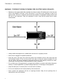
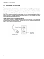


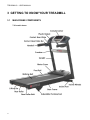

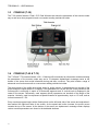
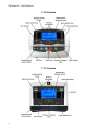
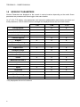


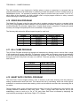
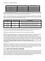


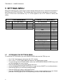


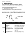
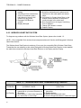
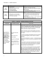

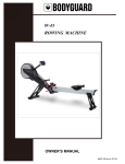
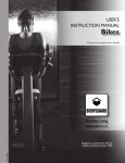
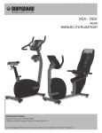


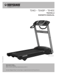

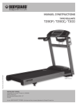
![[PF03] User manual for RED DOT CLUSTERS(EN) - Auto](http://vs1.manualzilla.com/store/data/005713867_1-90b7ac4617a5dc924635c3e0ee039806-150x150.png)