1
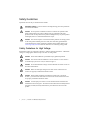
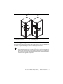
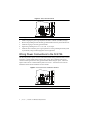
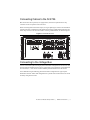
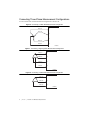
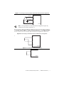
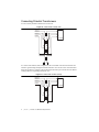
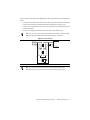
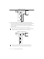
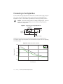
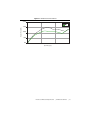
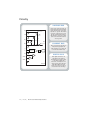
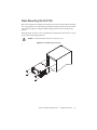
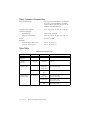
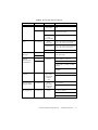
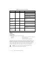
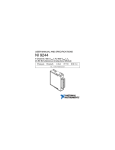
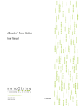
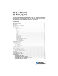
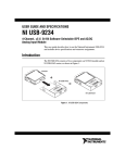
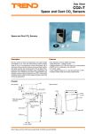
USER MANUAL AND SPECIFICATIONS NI 9725 Grid Automation System This document explains how to set up and install the National Instruments 9725 Grid Automation System. Figure 1. NI 9725 Parts Locator Diagram 1 4 5 6 3 7 8 2 9 10 11 12 13 1 2 3 4 5 6 7 NI 9725 Front View NI 9725 Rear View Front Handles Touchscreen Display Standby Switch Digital Connector Current Connectors 8 9 10 11 12 13 Voltage Connectors RJ-45 Ethernet Port LC Fiber Ethernet Port GPS Connector (F-Type) Power Connector with Backshell Earth Ground Terminal (Protective Earth) Safety Guidelines Operate the NI 9725 only as described in this manual. Hazardous Voltage This icon denotes a warning advising you to take precautions to avoid electrical shock. Caution Do not operate or install the NI 9725 in a manner not specified in this guide. Product misuse can result in a hazard. You can compromise the safety protection built into the product if the product is damaged in any way. If the product is damaged, return it to National Instruments for repair. Caution The NI 9725 requires a connection from the premises wire safety ground to the earth ground terminal (protective earth). The earth safety ground must be connected during use of this equipment to minimize shock hazards. Refer to the Connecting Safety Ground section for instructions on connecting safety ground. Safety Guidelines for High Voltage If hazardous voltages are connected to the device, take the following precautions. A hazardous voltage is a voltage greater than 42.4 Vpk or 60 VDC to earth ground. Caution Ensure that installation is performed only by qualified personnel. Caution The NI 9725 must be installed in a secure enclosure or a rack which is accessible only by the use of a tool, as shown in Figure 2. Caution Do not mix hazardous voltage circuits and human-accessible circuits on the same terminal block. Make sure that high-voltage devices and circuits connected to the NI 9725 are properly insulated from human contact. Caution Caution When module terminals are hazardous voltage LIVE (>42.4Vpk/ 60 VDC), you must ensure that all devices and circuits connected to the NI 9725 are properly insulated from human contact. Caution A main input power switch or circuit-breaker must be included in the installation as shown in Figure 2. The switch/circuit-breaker must be suitably located and easily reached, and clearly marked as the power disconnect device for this product. 2 | ni.com | NI 9725 User Manual and Specifications Figure 2. Secure Rack 1 2 3 4 6 5 1 2 3 Front view of secure rack Rear view of secure rack Main input power switch 5 4 5 6 NI 9725 inside a secure rack (front view) Lock securing the rack NI 9725 inside a secure rack (rear view) Connecting Safety Ground NI requires that you connect the NI 9725 to earth ground (protective earth) using the following steps. Refer to Figure 3 for a diagram of the NI 9725 safety ground terminal. Connecting Safety Ground (Protective Earth) The NI 9725 must have a safety ground (protective earth), which is connected by the installer to the premises safety ground system for safe operation. The installer must use a green or green/yellow wire for this purpose. The safety ground method shall be reliable and meet applicable safety codes. SAFETY GROUND CAUTION NI 9725 User Manual and Specifications | © National Instruments | 3 Figure 3. Safety Ground Terminal 1 1 Safety ground terminal 1. Attach a ring lug to a green or green/yellow wire that is 5.26 mm2 (10 AWG) or larger. 2. Remove the grounding nut from the safety ground terminal on the rear panel of the NI 9725. 3. Attach the ring lug to the safety ground terminal. 4. Tighten the grounding nut to 1.4 N · m (12 lb · in.) of torque. 5. Attach the other end of the green or green/yellow wire to the grounding electrode system of your facility using a method appropriate for the application. Wiring Power Connections to the NI 9725 The NI 9725 provides a power connector with backshell and a safety ground terminal, as shown in Figure 4. Connect neutral and line to the N (DC-) and L (DC+) terminals on the power connector and the ground to the safety ground terminal. When using DC power, connect the negative line to the DC- terminal and the positive line to DC+. You must use the connector backshell to ensure that the terminals are not accessible. Figure 4. Power Connector and Ground Terminal 2 1 1 4 Power connector with backshell | ni.com | NI 9725 User Manual and Specifications 2 Safety ground terminal Connecting Cables to the NI 9725 The NI 9725 has one ten-position, two eight-position, and two four-position barrier strip connectors on the rear panel for I/O connections. When connecting cables to the barrier strips, use ring or spade lugs to connect to the #8 studs for outside connections. Terminate the cable shields to the chassis ground terminal adjacent to the barrier strip connector. The NI 9725 includes 7 chassis ground terminals, as shown in Figure 5. Figure 5. NI 9725 Back Panel DIGITAL BUS 1 CURRENT VDC DI 0 DI 1 DI 2 DI 3 DI 4 DI 5 DI 6 DI 7 24– 24–300 + – IB IA + – + BUS 1 VOLTAGE IC – + IN – + VA IB – ENET 1 10/100/1000 + IC – + ENET 2 10/100/1000 VA IN – VN BUS 2 VOLTAGE BUS 2 CURRENT IA + VB VC – + VB VC VN – SYSTEM POWER GPS ANTENNA 110–300 VDC 100–240 VAC 50–60 Hz 26 W MAX Connecting to the Voltage Bus You can connect three-phase and single-phase measurement configurations to the NI 9725. The NI 9725 supports standard service levels up to 250 Vrms Line-to-Neutral (L-N) and 400 Vrms Line-to-Line (L-L). You can also connect standard potential transformers to the NI 9725. NI recommends using the following phase measurement configurations for typical power distribution networks. Other valid configurations are possible if the connections do not exceed the safety rating of the NI 9725. NI 9725 User Manual and Specifications | © National Instruments | 5 Connecting Three-Phase Measurement Configurations You can connect WYE or delta measurement configurations to the NI 9725. Figure 6. Connecting a 4-Wire WYE Measurement Configuration VA Phase A Phase B VB VC Phase C VN Neutral NI 9725 Figure 7. Connecting a High-Leg Delta Measurement Configuration Phase A VA Phase B VB Phase C VC Neutral VN NI 9725 Figure 8. Connecting a 3-Wire Delta Measurement Configuration Phase A VA Phase B VB Phase C VC NI 9725 6 | ni.com | NI 9725 User Manual and Specifications Figure 9. Connecting a Corner Grounded 2-Wire Delta Measurement Configuration Phase A VA Phase B VB Phase C VC NI 9725 Note Corner grounded 2-wire delta measurement configurations support only standard service levels up to 240 Vrms L-L. Connecting Single-Phase Measurement Configurations You can connect 3-wire or 2-wire single-phase measurement configurations to the NI 9725. Figure 10. Connecting a 3-Wire Measurement (Split Phase) Configuration VA VB VN NI 9725 Figure 11. Connecting a 2-Wire Measurement VA VN NI 9725 NI 9725 User Manual and Specifications | © National Instruments | 7 Connecting Potential Transformers You can connect potential transformers to the NI 9725. Figure 12. 4-Wire WYE-to-WYE (Full) Phase A VA Phase B VB Phase C VC Neutral VN NI 9725 In a 4-wire WYE-to-WYE (full) configuration, the VN terminal on the NI 9725 measures the neutral-to-ground voltage through the bottom transformer. You can use a lower ratio transformer due to the typically low voltages on the VN terminal. Ensure that you scale each NI 9725 channel reading with the corresponding transformer ratio. Figure 13. 4-Wire WYE-to-WYE (Partial) Phase A VA Phase B VB Phase C VC Neutral VN NI 9725 8 | ni.com | NI 9725 User Manual and Specifications For 4-wire WYE-to-WYE (partial) configurations, follow these guidelines for the best accuracy results. • Connect the VN terminal of the NI 9725 to the isolated ground of the potential transformer to reduce noise between the potential transformer ground and the chassis ground. • Connect the VN terminal of the NI 9725 as close as possible to the isolated ground of the potential transformer. • Use the L-N voltage measurements the NI 9725 returns as the default value. You can convert L-N voltage measurements to channel-to-earth ground by adding the Neutral terminal measurement to each of the V channels. Tip Figure 14. Delta-to-Delta Phase A VA Phase B VB Phase C VC NI 9725 1 1 Optional Tip You can use the Neutral channel for any other measurement if the measurement does not exceed the Neutral-to-Earth and L-N input range. NI 9725 User Manual and Specifications | © National Instruments | 9 Figure 15. Delta-to-WYE Phase A VA Phase B VB Phase C VC VN NI 9725 For delta-to-WYE configurations, follow these guidelines for the best accuracy results. • Connect the VN terminal of the NI 9725 to the isolated ground of the potential transformer to reduce noise between the potential transformer ground and the chassis ground. • Connect the VN terminal of the NI 9725 as close as possible to the isloated ground of the potential transformer. • Use the L-N voltage measurements the NI 9725 returns as the default value You can convert L-N voltage measurements to channel-to-earth ground by adding the Neutral terminal measurement to each of the V channels. Tip Figure 16. 3-Wire WYE-to-Delta Phase A VA Phase B VB Phase C VC NI 9725 You can use the Neutral channel for any other measurement if the measurement does not exceed the Neutral-to-Earth and L-N input range. Tip 10 | ni.com | NI 9725 User Manual and Specifications Figure 17. 3-Wire WYE-to-WYE Phase A VA Phase B VB Phase C VC VN NI 9725 For 3-wire WYE-to-WYE configurations, follow these guidelines for best accuracy results. • Connect the VN terminal of the NI 9725 to the isolated ground of the potential transformer to reduce noise between the potential transformer ground and the chassis ground. • Connec the VN terminal of the NI 9725 as close as possible to the isolated ground of the potential transformer. • Use the L-N voltage measurements the NI 9725 returns as the default value. You can convert L-N voltage measurements to channel-to-earth ground by adding the Neutral terminal measurement to each of the V channels. Tip Connecting to the Current Bus You can connect floating current sources to the NI 9725. The negative terminal of each current input channel is internally connected to the chassis ground of the NI 9725. Figure 18. Connecting a Floating Current Source Current Source I+ I– NI 9725 NI 9725 User Manual and Specifications | © National Instruments | 11 Connecting to the Digital Bus You can connect sourcing-output devices to the NI 9725. You must connect a supply voltage to VDC+ on the NI 9725. Input channels on the NI 9725 read ON or OFF depending on the threshold set by VDC+. The threshold is approximately 2/3 of the supply voltage on VDC+. Electrostatic Discharge (ESD) can damage the digital inputs. To prevent damage, use industry-standard ESD prevention measures during installation, maintenance, and operation. Caution Figure 19. Connecting a Sourcing-Output Device Sourcing-Output Device DI ≥ External + Power Supply – VDC+ 2/3 VDC– ISO Ground NI 9725 Output devices that you connect to the NI 9725 must be able to source enough current to overcome the NI 9725 input load (burden). The NI 9725 burden is dynamic and varies depending on the input voltage. Figure 20. Burden Current Per Channel 2.00 Max Min Burden Current (mA) 1.50 1.00 0.50 0.00 0.00 100.00 200.00 Input Voltage (V) 12 | ni.com | NI 9725 User Manual and Specifications 300.00 Figure 21. Burden Power Per Channel 200.00 Burden Power (mW) Max Min 150.00 100.00 50.00 0.00 0.00 100.00 300.00 200.00 Input Voltage (V) NI 9725 User Manual and Specifications | © National Instruments | 13 Circuitry VOLTAGE BUS Each voltage channel provides an independent signal path and ADC. Each terminal has the same input impedance to ground. The NI 9725 returns the voltage between each VA, VB, and VC terminal and the VN terminal as well as the voltage between the VN terminal and the chassis ground. VA VA V VB VB V VC VC V VN VN I+ I– Each current channel provides an independent signal path and ADC, enabling you to sample all four channels simultaneously. Shunt Resistor DI DIGITAL BUS ≥ VDC+ 2/3 VDC– NI 9725 14 | ni.com CURRENT BUS V | NI 9725 User Manual and Specifications Each digital channel uses an adjustable threshold that is determined by the supply voltage on the VDC+ terminal. The threshold is nominally 2/3 of the supply voltage and the NI 9725 reads ON or OFF if the input voltage on the channel is above or below the threshold voltage. Rack Mounting the NI 9725 The NI 9725 supports rack mounting. Secure the NI 9725 to the rack posts using four mounting screws appropriate for your rack and the top and bottom mounting positions on the rack mount rails as shown in Figure 22. Using the middle mounting positions on the rack mount rails is optional. When placing the NI 9725 in a rack, avoid placing the enclosure above a heat source, as rising heat can affect the operating temperature. Caution You must install the NI 9725 in a rack prior to use. Figure 22. Rack Mounting the NI 9725 NI 9725 User Manual and Specifications | © National Instruments | 15 Specifications This section provides performance specifications for the NI 9725. The following specifications are typical for the range -20 °C to 55 °C unless otherwise noted. Power Consumption Input voltage range and frequency....................100 to 240 VAC, 50 to 60 Hz; 110 to 300 VDC Maximum power consumption .........................26 W Analog Inputs ADC resolution .................................................24 bits Type of ADC.....................................................Delta-Sigma (with analog prefiltering) Sampling mode .................................................Simultaneous Internal master timebase (fM) Frequency..................................................12.8 MHz Accuracy ...................................................±100 ppm max Data rate range (fs) using internal master timebase Minimum ..................................................1.613 kS/s Maximum..................................................50 kS/s f M ÷ 256 Data rates (fs)..................................................... --------------------- , n = 1, 2, …, 31 n Digital Inputs Number of channels ..........................................8 digital input channels Input type ..........................................................Sinking Input voltage thresholds OFF state 24 V to 250 V....................................65% * Vsup - 4 V ON state 24 V to 250 V....................................73% * Vsup - 0.75 V Input current (10 V ≤ VIN ≤ 60 V)1 Maximum..................................................1.8 mA Minimum ..................................................1.3 mA 1 With input voltages between 10 V and 60 V, the input load (burden) is an approximately constant current. With input voltages between 60 V and 300 V, the input load is an approximately constant power. 16 | ni.com | NI 9725 User Manual and Specifications Input power (60 V ≤ VIN ≤ 300 V)1 Maximum.................................................. 150 mW Minimum .................................................. 75 mW Input delay time ................................................ 1 µs max1 Voltage Inputs Input voltage range (AIx and Neutral-to-GND, AIx-to-Neutral) Typical ...................................................... 500 Vpk Minimum .................................................. 497 V Overvoltage withstand ...................................... 500 Vrms continuous, 600 Vrms for 10 s Input coupling................................................... DC Input impedance, AIx-to-Ground and Neutral-to-GND ......................................... 1 MΩ Table 1. DC and AC Accuracy Percent of Reading (Gain Error) Percent of Range* (Offset Error) Max (-20 °C to 55 °C) 0.26% 0.14% Typ (23 °C ±5 °C) 0.05% 0.022% Measurement Conditions * Range equals 354 V (250 Vrms × √2) Note Accuracy specifications are valid for L-L, L-N and L-Earth measurements. Input noise over full bandwidth at 50 kS/s N-Earth and L-Earth ................................. 2.12 mVrms L-N and L-L.............................................. 3 mVrms Input noise over 60 Hz bandwidth at 50 kS/s N-Earth and L-Earth ................................. 73.5 uVrms L-N and L-L.............................................. 104 uVrms 1 For specified type test performance use a debounce time of at least 1 ms. NI 9725 User Manual and Specifications | © National Instruments | 17 Current Inputs Input current range Typical.......................................................500 Apk Nominal ....................................................1 Arms/5 Arms Overcurrent withstand.......................................20 Arms continuous, 500 Arms for 1 s 1250 Arms for one power cycle Input coupling ...................................................DC Input impedance, Ix+ to-Ix- .............................5 mΩ Note The negative terminals are internally connected to the chassis ground. Table 2. AC Accuracy Percent of Reading (Gain Error) Measurement Conditions Max (-20 °C to 55 °C) 0.62% Typ (23 °C ±5 °C) 0.16% Table 3. DC Accuracy Percent of Reading (Gain Error) Percent of Range* (Offset Error) Max (-20 °C to 55 °C) 0.8% 6.3% Typ (23 °C ±5 °C) 0.3% 1% Measurement Conditions * Range equals 5A Input noise over full bandwidth at 50 kS/s .......3.9 mArms Input noise over 60 Hz bandwidth at 50 kS/S ..135 uVrms Network Port 1 (Copper Ethernet) Connector..........................................................RJ45 Network interface .............................................10/100/1000 BaseT Communications rates.......................................10 Mbps, 100 Mbps, 1000 Mbps auto-negotiated 18 | ni.com | NI 9725 User Manual and Specifications Network Port 2 (Fiber Ethernet) Connector.......................................................... LC duplex Cabling.............................................................. 50-62.5/125μm, 50/125μm recommended to minimize internal transmission losses Network interface ............................................. 1000 BaseSX, multimode, full duplex Communication rate ......................................... 1000 Mbit/s GPS Input Pulse per second (PPS) accuracy...................... ±100 ns, >99% typical Connector.......................................................... F-Type Torque ............................................................... 1.4 N · m (12 lb · in.) Physical Characteristics If you need to clean the NI 9725, wipe it with a dry towel or a soft-bristle brush. The display should be cleaned with a microfiber cloth. Weight............................................................... 9.34 kg (20.6 lb) Dimensions ....................................................... 481.1 mm × 513.4 mm × 221.2 mm (18.94 in. × 20.21 in. × 8.71 in.) Note Visit ni.com/dimensions to find two-dimensional drawings and three-dimensional models for the NI 9725. Torque for shield points .................................... 1.4 N · m (12 lb · in.) Stud size for shield points................................. M4 (#8) Torque for safety ground terminal .................... 1.4 N · m (12 lb · in.) Current, Digital, and Voltage Connector Characteristics Bare wire........................................................... 5.26 mm2 cross-section diameter (10 AWG) to 0.33 mm2 cross-section diameter (22 AWG) copper conductor wire with 8 mm (0.3 in.) of insulation stripped from the end Ring/spade terminals Stud size.................................................... M4 (#8) Maximum width ....................................... 9.40 mm (0.370 in.) Torque for barrier strip terminals...................... 1.4 N · m (12 lb · in.) NI 9725 User Manual and Specifications | © National Instruments | 19 Power Connector Characteristics Screw-terminal wiring ......................................5.26 mm2 cross-section diameter (10 AWG) to 0.21 mm2 cross-section diameter (24 AWG) copper conductor wire with 7 mm (0.3 in.) of insulation stripped from the end Torque for screw terminal.................................0.5 N · m to 0.6 N · m (4 lb · in. to 5 lb · in.) Connector Securement Securement type........................................Screw flanges provided Torque for screw flanges...........................0.5 N · m to 0.6 N · m (4 lb · in. to 5 lb · in.) Ferrules .............................................................0.25 mm2 to 4 mm2 Backshell Torque for strain-relief screws ..................0.31 N · m (2.7 lb · in) Torque for captive screws .........................0.56 N · m (5.0 lb · in) Type Tests Table 4. NI 9725 Type Tests Description Standards Ports Radiated Emission CISPR 22 Enclosure Class A Conducted Emission CISPR 22 Enclosure Class A IEC 61000-4-18 Power, Digital Inputs, Analog Inputs 2.5 kV common mode, 1 kV transverse mode C37.90.1 Ethernet, GPS 2.5 kV common mode IEC 61000-4-18 Power, Analog Inputs 4 kV common mode, 2 kV transverse mode Digital Inputs 4 kV common mode, 1 kV transverse mode GPS 2 kV common mode 1 MHz Damped Oscillatory Wave 100 kHz Damped Oscillatory Wave 20 | ni.com | NI 9725 User Manual and Specifications Levels Table 4. NI 9725 Type Tests (Continued) Description Fast Transients Surge Standards Ports IEC 61000-4-4 Power, Analog Inputs 4 kV common mode and transverse mode C37.90.1 Digital Inputs 4 kV common mode, 2 kV transverse mode Ethernet, GPS, Functional Earth 4 kV common mode IEC 61000-4-5 Power, Analog Inputs 0.5 kV, 1 kV, 2 kV, 4 kV common mode; 0.5 kV, 1 kV, 2 kV transverse mode Digital Inputs 0.5 kV, 1 kV, 2 kV, 4 kV common mode, 0.5 kV, 1 kV, 2 kV transverse mode GPS Electrostatic Discharge IEC 61000-4-2 Radiated Electromagnetic Field Immunity IEC 61000-4-3 Levels 0.5 kV, 1 kV, 2 kV common mode Enclosure* 8 kV contact discharge, 15 kV air discharge Enclosure 20 V/m 80 MHz to 1000 MHz C37.90.3 C37.90.2 10 V/m 1.4 GHz to 2.7 GHz 20 V/m 80 MHz, 160 MHz, 450 MHz, 900 MHz 10 V/m 380 MHz, 1850 MHz, 2150 MHz Conducted Immunity IEC 61000-4-6 Power Frequency Voltage Immunity IEC 61000-4-16 DC Voltage Dips IEC 61000-4-29 Power, Digital Inputs, Analog Inputs, Ethernet, GPS 10 V 0.15 MHz to 80 MHz Power, Digital Inputs, Analog Inputs, Ethernet 30 V continuous Power 10 V 27 MHz, 68 MHz 300 V for 1 s 0% 10 ms to 1000 ms 40% 200 ms 70% 500 ms NI 9725 User Manual and Specifications | © National Instruments | 21 Table 4. NI 9725 Type Tests (Continued) Description AC Voltage Dips Standards Ports IEC 61000-4-29 Power Levels 0% 0.5 to 25 cycles (50/60 Hz) 40% 10 cycles at 50 Hz 40% 12 cycles at 60 Hz 70% 25 cycles at 50 Hz 70% 30 cycles at 60 Hz DC Voltage Interruptions IEC 61000-4-29 Power 0% for 5s AC Voltage Interruptions IEC 61000-4-11 Power 0% for 250 cycles at 50 Hz Ripple on DC Power IEC 61000-4-17 Power Power Frequency Magnetic Field IEC 61000-4-8 Enclosure Damped Oscillatory Magnetic Field IEC 61000-4-10 * 0% for 300 cycles at 60 Hz 15% at 100 Hz and 120 Hz 100 A/m continuous 300 A/m for 3 s Enclosure 30 A/m at 1 MHz Parts accessible in normal use when rack mounted. Safety Voltage Bus Maximum working voltage, channel-to-earth ground Continuous ................................................250 Vrms/250 VDC, Measurement Category III Withstand ..................................................2400 Vrms/2400 VDC Verified by 2s dielectric withstand test Measurement Category III is for measurements performed in the building installation at the distribution level. This category refers to measurements on hard-wired hardware such as hardware in fixed installations, distribution boards, and circuit breakers. Other examples are wiring, including cables, bus bars, junction boxes, switches, socket outlets in the fixed installation, and stationary motors with permanent connections to fixed installations. Caution Do not connect the NI 9725 voltage bus to signals or use for measurements within Measurement Categories IV. 22 | ni.com | NI 9725 User Manual and Specifications Digital Bus Maximum working voltage, channel-to-COM . 300 VDC max Isolation Channel-to-channel................................... None Channel-to-earth ground Continuous........................................ 300 Vrms/300 VDC, Measurement Category II Withstand .......................................... 2400 Vrms/2400 VDC Verified by 2s dielectric withstand test Measurement Category II is for measurements performed on circuits directly connected to the electrical distribution system. This category refers to local-level electrical distribution, such as that provided by a standard wall outlet, for example, 115 V for U.S. or 230 V for Europe. Caution Do not connect the NI 9725 digital bus to signals or use for measurements within Measurement Categories III or IV. Current Bus The negative terminal of each current input channel is tied internally to the chassis ground. Power Input Isolation Line and neutral-to-earth ground Continuous........................................ 250 Vrms Overvoltage Category II Withstand .......................................... 2400 Vrms/2400 VDC Verified by 2s dielectric withstand test Overvoltage Category II is for measurements performed on circuits directly connected to the electrical distribution system. This category refers to local-level electrical distribution, such as that provided by a standard wall outlet, for example, 115 V for U.S. or 230 V for Europe. Caution Do not connect the NI 9725 digital bus to signals or use for measurements within Measurement Categories III or IV. Safety Standards This product meets the requirements of the following standards of safety for electrical equipment for measurement, control, and laboratory use: • IEC 61010-1, EN 61010-1 • UL 61010-1, CSA 61010-1 Note For UL and other safety certifications, refer to the product label or the Online Product Certification section. NI 9725 User Manual and Specifications | © National Instruments | 23 Electromagnetic Compatibility This product meets the requirements of the following EMC standards for electrical equipment for measurement, control, and laboratory use: • EN 61326-1 (IEC 61326-1): Class A emissions; Industrial immunity • EN 55011 (CISPR 11): Group 1, Class A emissions • EN 55022 (CISPR 22): Class A emissions • EN 55024 (CISPR 24): Immunity • AS/NZS CISPR 11: Group 1, Class A emissions • AS/NZS CISPR 22: Class A emissions • FCC 47 CFR Part 15B: Class A emissions • ICES-001: Class A emissions In the United States (per FCC 47 CFR), Class A equipment is intended for use in commercial, light-industrial, and heavy-industrial locations. In Europe, Canada, Australia and New Zealand (per CISPR 11) Class A equipment is intended for use only in heavy-industrial locations. Note Group 1 equipment (per CISPR 11) is any industrial, scientific, or medical equipment that does not intentionally generate radio frequency energy for the treatment of material or inspection/analysis purposes. Note Note For EMC eclarations and certifications, and additional information, refer to the Online Product Certification section. CE Compliance This product meets the essential requirements of applicable European Directives as follows: • 2006/95/EC; Low-Voltage Directive (safety) • 2004/108/EC; Electromagnetic Compatibility Directive (EMC) Online Product Certification To obtain product certifications and the Declaration of Conformity (DoC) for this product, visit ni.com/certification, search by module number or product line, and click the appropriate link in the Certification column. Shock and Vibration This product meets the requirements of the following standards for shock and vibration. • IEC 60255-21-1: 1988 Electrical relays, Part 21:Section One: Vibration tests (sinusoidal), Class 1 • IEC 60255-21-2: 1988 Electrical relays, Part 21: Section Two: Shock and Bump tests, Class 1 • IEC 60255-21-3: 1993 Electrical relays, Part 21: Section Three: Seismic tests, Class 1 24 | ni.com | NI 9725 User Manual and Specifications Environmental Operating temperature (IEC 60068-2-1, IEC 60068-2-2) ..................... -20 °C to 55 °C Storage temperature (IEC 60068-2-1, IEC 60068-2-2) ..................... -40 °C to 85 °C Ingress protection ............................................. IP 30 Operating humidity (IEC 60068-2-78) ............. 10% RH to 90% RH, noncondensing Storage humidity (IEC 60068-2-78)................. 5% RH to 95% RH, noncondensing Pollution Degree (IEC 60664).......................... 2 Maximum altitude............................................. 2,000 m Indoor use only. Environmental Management NI is committed to designing and manufacturing products in an environmentally responsible manner. NI recognizes that eliminating certain hazardous substances from our products is beneficial to the environment and to NI customers. For additional environmental information, refer to the Minimize Our Environmental Impact web page at ni.com/environment. This page contains the environmental regulations and directives with which NI complies, as well as other environmental information not included in this document. Waste Electrical and Electronic Equipment (WEEE) At the end of the product life cycle, all products must be sent to a WEEE recycling center. For more information about WEEE recycling centers, National Instruments WEEE initiatives, and compliance with WEEE Directive 2002/96/EC on Waste and Electronic Equipment, visit ni.com/environment/ weee. EU Customers ⬉ᄤֵᙃѻક∵ᶧࠊㅵ⧚ࡲ⊩ ˄Ё RoHS˅ Ёᅶ᠋ National Instruments ヺড়Ё⬉ᄤֵᙃѻકЁ䰤ࠊՓ⫼ᶤѯ᳝ᆇ⠽䋼ᣛҸ (RoHS)DŽ݇Ѣ National Instruments Ё RoHS ড়㾘ᗻֵᙃˈ䇋ⱏᔩ ni.com/ environment/rohs_chinaDŽ (For information about China RoHS compliance, go to ni.com/environment/rohs_china.) NI 9725 User Manual and Specifications | © National Instruments | 25 Worldwide Support and Services The NI website is your complete resource for technical support. At ni.com/support you have access to everything from troubleshooting and application development self-help resources to email and phone assistance from NI Application Engineers. Visit ni.com/services for NI Factory Installation Services, repairs, extended warranty, and other services. Visit ni.com/register to register your NI product. Product registration facilitates technical support and ensures that you receive important information updates from NI. A Declaration of Conformity (DoC) is our claim of compliance with the Council of the European Communities using the manufacturer’s declaration of conformity. This system affords the user protection for electromagnetic compatibility (EMC) and product safety. You can obtain the DoC for your product by visiting ni.com/certification. If your product supports calibration, you can obtain the calibration certificate for your product at ni.com/calibration. NI corporate headquarters is located at 11500 North Mopac Expressway, Austin, Texas, 78759-3504. NI also has offices located around the world. For telephone support in the United States, create your service request at ni.com/support or dial 1 866 ASK MYNI (275 6964). For telephone support outside the United States, visit the Worldwide Offices section of ni.com/niglobal to access the branch office websites, which provide up-to-date contact information, support phone numbers, email addresses, and current events. 26 | ni.com | NI 9725 User Manual and Specifications Refer to the NI Trademarks and Logo Guidelines at ni.com/trademarks for more information on NI trademarks. Other product and company names mentioned herein are trademarks or trade names of their respective companies. For patents covering NI products/technology, refer to the appropriate location: Help»Patents in your software, the patents.txt file on your media, or the National Instruments Patents Notice at ni.com/patents. You can find information about end-user license agreements (EULAs) and third-party legal notices in the readme file for your NI product. Refer to the Export Compliance Information at ni.com/legal/export-compliance for the NI global trade compliance policy and how to obtain relevant HTS codes, ECCNs, and other import/export data. NI MAKES NO EXPRESS OR IMPLIED WARRANTIES AS TO THE ACCURACY OF THE INFORMATION CONTAINED HEREIN AND SHALL NOT BE LIABLE FOR ANY ERRORS. U.S. Government Customers: The data contained in this manual was developed at private expense and is subject to the applicable limited rights and restricted data rights as set forth in FAR 52.227-14, DFAR 252.227-7014, and DFAR 252.227-7015. © 2015 National Instruments. All rights reserved. 376972A-01 Aug15