1
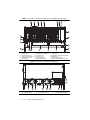
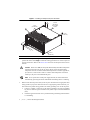
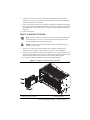
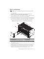
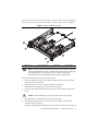
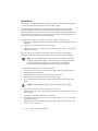
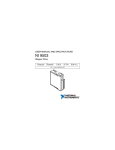
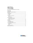
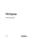
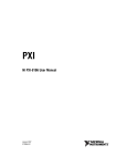
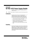
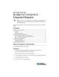
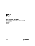
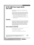
GETTING STARTED GUIDE NI PXIe-1086 The manual includes instructions for installing and configuring your NI PXIe-1086 chassis and PXI Express system. Contents What You Need to Get Started ................................................................................................. 1 Safety Information .................................................................................................................... 2 Electrical ................................................................................................................................... 3 AC Input ........................................................................................................................... 3 Chassis Parts ............................................................................................................................. 3 Preparing the Environment ....................................................................................................... 5 Installing the PXI Express System ........................................................................................... 5 Step 1: Set Up the Chassis................................................................................................ 5 Step 2: Install the Controller............................................................................................. 7 Step 3: Install Modules ..................................................................................................... 9 Step 4: Configure the System In Software Using MAX .................................................. 10 Step 5: Connect Signals to Modules................................................................................. 10 Where To Go Next ........................................................................................................... 10 Maintenance.............................................................................................................................. 10 Service Interval................................................................................................................. 10 Cleaning............................................................................................................................ 11 Replacing a Modular Power Supply......................................................................................... 11 Removal............................................................................................................................ 11 Installation ........................................................................................................................ 14 Worldwide Support and Services ............................................................................................. 15 What You Need to Get Started The NI PXIe-1086 chassis kit contains the following items: NI PXIe-1086 chassis Filler panels NI PXIe-1086 User Manual Software media with PXI Platform Services 14.0 or later Read Me First: Safety and Electromagnetic Compatibility Chassis number labels Inhibit fault cable connector Note An AC power cable is also required, but not included in the NI PXIe-1086 chassis kit. Safety Information Before undertaking any troubleshooting, maintenance, or exploratory procedure, carefully read the following caution notices. Protection equipment may be impaired if equipment is not used in the manner specified. Caution This equipment contains voltage hazardous to human life and safety, and is capable of inflicting personal injury. • Chassis Grounding—The chassis requires a connection from the premise wire safety ground to the chassis ground. The earth safety ground must be connected during use of this equipment to minimize shock hazards. Refer to refer to Chapter 2, Installation and Configuration, of the NI PXIe-1086 User Manual for instructions on connecting safety ground. • Live Circuits—Operating personnel and service personnel must not remove protective covers when operating or servicing the chassis. Adjustments and service to internal components must be undertaken by qualified service technicians. During service of this product, the mains connector to the premise wiring must be disconnected. Dangerous voltages may be present under certain conditions; use extreme caution. • Explosive Atmosphere—Do not operate the chassis in conditions where flammable gases are present. Under such conditions, this equipment is unsafe and may ignite the gases or gas fumes. • Part Replacement—Only service this equipment with parts that are exact replacements, both electrically and mechanically. Contact National Instruments for replacement part information. Installation of parts with those that are not direct replacements may cause harm to personnel operating the chassis. Furthermore, damage or fire may occur if replacement parts are unsuitable. • Modification—Do not modify any part of the chassis from its original condition. Unsuitable modifications may result in safety hazards. 2 | ni.com | NI PXIe-1086 Getting Started Guide Electrical The following section provides information about the NI PXIe-1086 AC input. Note Refer to the NI PXIe-1086 User Manual for full specifications. AC Input Input voltage range ........................................... 100 to 240 VAC Operating voltage range1 .................................. 90 to 264 VAC Input current rating ........................................... 12 to 6 A Input frequency range ....................................... 50/60 Hz Operating frequency range1 .............................. 47 to 63 Hz Over-current protection .................................... All outputs protected from short circuit and overload with automatic recovery Efficiency.......................................................... 70% typical Power disconnect .............................................. The AC power cables provide main power disconnect. Do not position the equipment so that it is difficult to disconnect the power cord. The front panel power switch causes the internal chassis power supply to provide DC power to the CompactPCI/PXI Express backplane. You also can use the front panel terminal block 4-pin connector and power mode switch to control the internal chassis power supply. Chassis Parts The following figures show the key features of the NI PXIe-1086 chassis front and back panels. 1 This operating range is guaranteed by design. NI PXIe-1086 Getting Started Guide | © National Instruments | 3 Figure 1. Front View of the NI PXIe-1086 Chassis (with Optional Filler Panels) 2 1 5 4 3 7 6 8 NI PXIe-1086 9 16 10 15 14 9 9 1 2 3 4 5 6 11 10 13 Power Inhibit Switch Status LEDs Inhibit/Fault Connector Earth (Ground) Terminal Backplane Connectors Clk10 Output 7 8 9 10 11 9 11 12 Clk10 Input PXI Filler Panels (Optional) Removable Feet Fan Door Latch PXI Express Hybrid Peripheral Slots (16x) 12 PXI Express PXI Express System Timing Slot 13 PXI Express System Controller Slot 14 Ethernet Port 15 Chassis Carry Handle 16 System Controller Expansion Slots Figure 2. Rear View of the NI PXIe-1086 Chassis 6 5 1 1 2 4 2 Power Supply Cooling Fan Power Supply Handle | ni.com | 1 1 3 4 2 1 Chassis Power Connectors Chassis Ground Screw NI PXIe-1086 Getting Started Guide 3 5 6 4 Inhibit Mode Selector Switch Fan Speed Selector Switch Preparing the Environment Ensure the environment you are using the NI PXIe-1086 in meets the following specifications. Ambient temperature range .............................. 0 to 50 °C (Tested in accordance with IEC 60068-2-1 and IEC 60068-2-2. Meets MIL-PRF-28800F Class 3 temperature limits.) Relative humidity range.................................... 5 to 95%, noncondensing (Tested to temperature and humidity levels specified in MIL-PRF-28800F) Maximum altitude............................................. 4600 m (570 mbar) (at 25 °C ambient) Note Fan speed selector must be set to High to meet the maximum altitude specification. Pollution Degree ............................................... 2 For indoor use only. Note Refer to the NI PXIe-1086 User Manual for full specifications. Installing the PXI Express System Step 1: Set Up the Chassis 1. Inspect the chassis interior and exterior for damage. If damage appears to have been caused during shipment, file a claim with the carrier. 2. If you are installing the chassis in an instrument rack, install the rack mount kit for the chassis (sold separately). Refer to the instructions supplied with the rack mount kit. 3. Position the chassis as shown in the following figure, so there is adequate clearance between the chassis and surrounding equipment to ensure proper chassis cooling. NI PXIe-1086 Getting Started Guide | © National Instruments | 5 Figure 3. Installing a PXI Express System Controller 2 1.75 in. (44.45 mm) 3.00 in. (76.20 mm) from air filter retainer 1 1.75 in. (44.45 mm) NI PX Ie -10 86 1.75 in. (44.45 mm) 1 Air Exhaust Vent 4. 2 Primary Air Intake Vents Set the chassis fan speed to High or Auto using the fan-speed selector switch on the rear panel of the chassis. Select High for maximum cooling performance or Auto for improved acoustic performance. Refer to the Chassis Parts section for the fan-speed selector switch location. When set to Auto, the fan speed is determined by the ambient temperature outside the fan intake vents on the rear of the chassis. Ensure that this ambient temperature does not exceed the rated ambient temperature as stated in Appendix A, Specifications, of the NI PXIe-1086 User Manual. If the temperature exceeds the stated spec, the power switch LED blinks green. Caution Note If two system fans or both power supply fans fail, the chassis shuts down automatically, protecting the chassis and modules from damage due to overheating. 5. 6 Make sure the electrical power outlet you use to power the chassis has an appropriate earth safety ground. If your power outlet does not have an appropriate ground connection, you must connect the premise safety ground to the chassis grounding screw on the rear panel: | a. Connect a 16 AWG (1.3 mm) wire to the chassis grounding screw using a grounding lug. The wire must have green insulation with a yellow stripe or must be noninsulated (bare). b. Attach the opposite end of the wire to permanent earth ground using toothed washers or a toothed lug. ni.com | NI PXIe-1086 Getting Started Guide 6. Connect the AC power source to the chassis before installing the system controller or modules. The AC power cord grounds the chassis and protects it from electrical damage while you install the system controller. 7. Power on the chassis. Make sure the switch LED is steady green (not flashing), indicating the chassis is powered on and operating normally. If it is not, refer to Chapter 2, Installation and Configuration, of the NI PXIe-1086 User Manual for more information about LED indicators. 8. Power off the chassis. Step 2: Install the Controller Note Be sure the chassis is connected to an AC power source before installing the system controller. The AC power cord grounds the chassis and protects it from electrical damage while you install the controller. Refer to your PXI Express system controller user manual for specific instructions and warnings. Caution 1. Inspect the slot 1 pins on the chassis backplane for any bending or damage prior to installation. Do not install the system controller if any pins are bent or damaged. 2. Install the system controller into the system controller slot (slot 1, indicated by the red card guides) by first placing the system controller PCB into the front of the card guides (top and bottom). Slide the system controller to the rear of the chassis, making sure the injector/ejector handle is pushed down as shown in the following figure. Figure 4. Installing a PXI Express System Controller 1 NI PX Ie-1 08 6 2 3 4 1 2 System Controller Front Panel Mounting Screws (4x) PXI Express System Controller 3 4 Injector/Ejector Handle NI PXIe-1086 Chassis NI PXIe-1086 Getting Started Guide | © National Instruments | 7 3. When you begin to feel resistance, pull up on the injector/ejector handle to seat the system controller fully into the chassis frame. Secure the system controller front panel to the chassis using the system controller front panel mounting screws. The following figure shows a PXI Express system controller installed in the system controller slot of a chassis. Figure 5. PXI Express System Controller Installed in an NI PXIe-1086 Chassis 1 2 NI PX Ie-1 0 86 3 1 NI PXIe-1086 Chassis 2 PXI Express System Controller 3 Injector/Ejector Rail 4. Connect the keyboard, mouse, and monitor to the appropriate connectors. Connect devices to ports as required by your system configuration. 5. Power on the chassis. Verify that the system controller boots. If the system controller does not boot, refer to the Troubleshooting section or your system controller user manual. 8 | ni.com | NI PXIe-1086 Getting Started Guide Step 3: Install Modules Note Refer to your module user manual for specific instructions and warnings. 1. Power off the chassis. 2. Inspect the slot pins on the chassis backplane for any bending or damage prior to installation. Do not install a module if the backplane is damaged. 3. To prevent damage to the chassis, ensure that you are installing the module in the correct type of slot. Refer to the Chassis Parts section for the slot descriptions. 4. Install the module into the chassis slot by first placing the module card PCB into the front of the card guides (top and bottom), as shown in the following figure. Slide the module to the rear of the chassis, making sure that the injector/ejector handle is pushed down. Figure 6. Installing PXI, PXI Express, or CompactPCI Peripheral Modules 5 4 NI PX Ie-1 08 6 3 2 6 1 1 2 3 Injector/Ejector Handle PXI Peripheral Module Peripheral Module Front Panel Mounting Screws (2x) 4 5 6 PXI Express System Controller NI PXIe-1086 Chassis Injector/Ejector Rail 5. When you begin to feel resistance, push up on the injector/ejector handle to seat the module fully into the chassis frame. Secure the module front panel to the chassis using the module front-panel mounting screws. 6. Install filler panels (provided with the chassis) in unused slots to maintain proper module cooling performance. Secure the panels with the captive mounting screws provided. 7. If needed, install optional EMC filler panels (sold separately) for extra electromagnetic shielding. For more information about using EMC filler panels, refer to ni.com. NI PXIe-1086 Getting Started Guide | © National Instruments | 9 8. If needed, install optional slot blockers (sold separately) to improve the chassis cooling performance. For more information about using PXI slot blockers, refer to ni.com. 9. Power on the chassis again. If the power inhibit switch indicator LED is steady green (not flashing), the chassis is powered on and operating normally. If the LED is not steady green, refer to Chapter 2, Installation and Configuration, of the NI PXIe-1086 User Manual for more information about LED indicators. Step 4: Configure the System In Software Using MAX Note The configuration steps for single or multiple-chassis systems are the same. 1. If PXI Platform Services is not installed on your system, install it from the software CD included with your chassis. 2. Launch MAX from the desktop shortcut or the Start menu. 3. In the Configuration tree, click the Devices and Interfaces branch to expand it. 4. If the PXI system controller has not yet been configured, it is labeled PXI System (Unidentified). Right-click this entry to display the pop-up menu, then select the appropriate system controller model from the Identify As submenu. 5. Click the PXI system controller. The chassis (or multiple chassis in a multichassis configuration) is listed below it. Identify each chassis by right-clicking its entry, then selecting the appropriate chassis model through the Identify As submenu. Further expanding the PXI System branch shows all devices in the system that NI-VISA can recognize. When your system controller and all your chassis are identified, the required pxisys.ini file is complete. Step 5: Connect Signals to Modules Refer to your PXI module documentation for information about connecting signals to your devices. Where To Go Next • User manuals and specifications for all devices in your system at ni.com/manuals. • NI PXIe-1086 User Manual at ni.com/manuals for more information about the chassis backplane, remote voltage monitoring and control, system initialization files, and pinouts. Maintenance Service Interval Clean dust from the chassis exterior (and interior) as needed, based on the operating environment. Periodic cleaning increases reliability. 10 | ni.com | NI PXIe-1086 Getting Started Guide Cleaning Cleaning procedures consist of exterior and interior cleaning of the chassis. Refer to your module user documentation for information on cleaning the individual CompactPCI or PXI Express modules. Caution Always disconnect all power cables before cleaning or servicing the chassis. Interior Cleaning Use a dry, low-velocity stream of air to clean the interior of the chassis. Use a soft-bristle brush for cleaning around components. Exterior Cleaning Clean the exterior surfaces of the chassis with a dry lint-free cloth or a soft-bristle brush. If any dirt remains, wipe with a cloth moistened in a mild soap solution. Remove any soap residue by wiping with a cloth moistened with clear water. Do not use abrasive compounds on any part of the chassis. Avoid getting moisture inside the chassis during exterior cleaning, especially through the top vents. Use just enough moisture to dampen the cloth. Caution Do not wash the front- or rear-panel connectors or switches. Cover these components while cleaning the chassis. Caution Caution Do not use harsh chemical cleaning agents; they may damage the chassis. Avoid chemicals that contain benzene, toluene, xylene, acetone, or similar solvents. Replacing a Modular Power Supply This section describes how to remove and install a modular power supply for the NI PXIe-1086 chassis. Caution Do not use a power supply from another chassis. Doing so may damage your chassis and the power supply. Removal The NI PXIe-1086 power supply (part number 782106-01) is a replacement part for the NI PXIe-1086 chassis. Before attempting to replace a power supply, verify that there is adequate clearance behind the chassis. The power supplies for this chassis are redundant and hot swappable. If both power supplies are installed and functional, you can remove either without disconnecting main AC power from the system. If both power supplies are installed, and one has failed, you can remove the failed supply without disconnecting main AC power from the system. NI PXIe-1086 Getting Started Guide | © National Instruments | 11 Complete the following steps to remove a power supply from the rear of the chassis, as shown in Figure 7: Caution Before handling the power supply, allow the fan to stop spinning. 1. Disengage the two captive screws on the rear of the power supply with a flat-blade screwdriver. 2. Extend the collapsible handle and pull the power supply out of the chassis. Figure 7. Removing Power Supply from NI PXIe-1086 Chassis 1 2 3 2 1 12 Power Supply | ni.com | 2 Captive Screw NI PXIe-1086 Getting Started Guide 3 Collapsible Handle If access to the rear of the chassis is not available, you still can remove the power supplies by removing the entire power drawer from the chassis. The power drawer is shown in Figure 8. Figure 8. NI PXIe-1086 Power Drawer 4 1 2 3 1 2 1 Captive Screw 2 Power Drawer Lever 3 Side Latch 4 Power Supply Note If you are using the NI PXIe-1086 and NI SC Express modules with front mounting terminal blocks together, you must remove the SC Express module front mount terminal blocks to access the power drawer. Refer to your module documentation for more information about removing the terminal blocks. Complete the following steps to remove the power drawer: 1. Loosen the drawer lever captive screws with a flat-blade screwdriver until the threads disengage from the chassis frame. 2. Rotate the drawer levers to eject the drawer from the chassis frame. 3. Pull the drawer about halfway out until the side latches engage. 4. Press in the side latches on both sides to release the drawer and continue to pull out the drawer. Caution Before handling the power supply, allow the fan to stop spinning. 5. Place the drawer on a table surface to remove the power supply. 6. Disengage the two captive screws on the rear of the power supply with a flat-blade screwdriver. (Refer to Figure 7.) 7. Extend the collapsible handle and pull the power supply out of the chassis. (Refer to Figure 7.) NI PXIe-1086 Getting Started Guide | © National Instruments | 13 Installation Ensure there is no visible damage to the new power supply before installing it. Verify that there is no foreign material inside the connector on the new power supply. The power supplies for this chassis are redundant and hot swappable. If one power supply already is installed and functional, you can install the second power supply without first disconnecting main AC power from the system. If no power supplies are installed or functional in the system, you must remove main power from the system by disconnecting the power cable from the AC power connector on the chassis front panel. Complete the following steps to install a power supply from the rear of the chassis: 1. Slide the power supply into an empty slot with the connector facing toward the chassis until it engages. 2. Fold down the collapsible handle on the power supply. 3. Tighten the two captive screws on the rear of the power supply to 11.5 lb · in. torque with a flat-blade screwdriver. If access to the rear of the chassis is not available, you still can install power supplies by removing the entire power drawer from the chassis. The power drawer is shown in Figure 8. Note If you are using the NI PXIe-1086 and NI SC Express modules with front mounting terminal blocks together, you must remove the SC Express module front mount terminal blocks to access the power drawer. Refer to your module documentation for more information about removing the terminal blocks. Complete the following steps to remove the power drawer: 1. Loosen the drawer lever captive screws with a flat-blade screwdriver until the threads disengage from the chassis frame. 2. Rotate the drawer levers to eject the drawer from the chassis frame. 3. Pull the drawer about halfway out until the side latches engage. 4. Press in the side latches on both sides to release the drawer and continue to pull out the drawer. Caution Before handling the power supply, allow the fan to stop spinning. 5. Place the drawer on a table surface to install the power supply. 6. Slide the power supply into an empty slot with the connector facing toward inside of drawer until it engages. 7. Fold down the collapsible handle on the power supply. 8. Tighten the two captive screws on the rear of the power supply to 11.5 lb · in. torque with a flat-blade screwdriver. 9. Reinstall the power drawer. When reinstalling the drawer, tighten the drawer lever captive screws to 11.5 lb · in. torque. 14 | ni.com | NI PXIe-1086 Getting Started Guide Worldwide Support and Services The National Instruments website is your complete resource for technical support. At ni.com/ support you have access to everything from troubleshooting and application development self-help resources to email and phone assistance from NI Application Engineers. Visit ni.com/services for NI Factory Installation Services, repairs, extended warranty, and other services. Visit ni.com/register to register your National Instruments product. Product registration facilitates technical support and ensures that you receive important information updates from NI. National Instruments corporate headquarters is located at 11500 North Mopac Expressway, Austin, Texas, 78759-3504. National Instruments also has offices located around the world. For telephone support in the United States, create your service request at ni.com/support or dial 1 866 ASK MYNI (275 6964). For telephone support outside the United States, visit the Worldwide Offices section of ni.com/niglobal to access the branch office websites, which provide up-to-date contact information, support phone numbers, email addresses, and current events. NI PXIe-1086 Getting Started Guide | © National Instruments | 15 Refer to the NI Trademarks and Logo Guidelines at ni.com/trademarks for more information on National Instruments trademarks. Other product and company names mentioned herein are trademarks or trade names of their respective companies. For patents covering National Instruments products/technology, refer to the appropriate location: Help»Patents in your software, the patents.txt file on your media, or the National Instruments Patents Notice at ni.com/patents. You can find information about end-user license agreements (EULAs) and third-party legal notices in the readme file for your NI product. Refer to the Export Compliance Information at ni.com/legal/export-compliance for the National Instruments global trade compliance policy and how to obtain relevant HTS codes, ECCNs, and other import/export data. NI MAKES NO EXPRESS OR IMPLIED WARRANTIES AS TO THE ACCURACY OF THE INFORMATION CONTAINED HEREIN AND SHALL NOT BE LIABLE FOR ANY ERRORS. U.S. Government Customers: The data contained in this manual was developed at private expense and is subject to the applicable limited rights and restricted data rights as set forth in FAR 52.227-14, DFAR 252.227-7014, and DFAR 252.227-7015. © 2014 National Instruments. All rights reserved. 374548A-01 Oct14