1
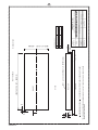
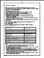
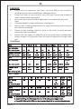
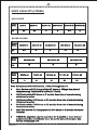
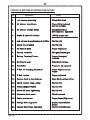
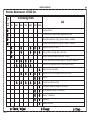
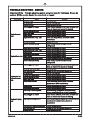
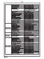
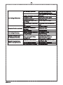
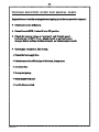
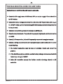
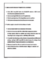
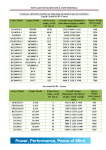
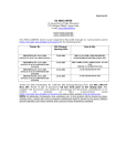
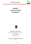
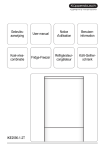
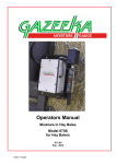
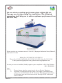
P
O
W
E
R
BY
KIRLOSKAR
We can achieve excellent performance from a Silent DG set,
if proper care is taken during its installation. (The following
suggestions shall help you to achieve optimum performance from
the D.G. Set.)
For Assistance
Please contact our customer care at C-266-267, Mayapuri Industrial Area, Phase-II,
New Delhi-110 064
Mobile No. 9871590738, 9871590745
Phone No. 011-28114072 (D), 28111510, 28113231, Fax No. 28113149
e-mail: [email protected], [email protected]
In case you are not satisfied, kindly register your complaint to Mr. Gopi Nathan
Mob. : 9910448420
Note:
1.
2.
JAKSON & CO.
Please always sign the report made by our Service Engineer.
Warranty is applicable for two years for engine & alternator only
subject to use of Kirloskar K-Oil Premium, Kirloskar genuine filters,
K cool super plus and services sourced through KOEL authorized
Service Dealer.
INDEX
S. NO.
DESCRIPTION
1.
SELECTION OF SITE
1
2.
FOUNDATION DETAILS &
GUIDELINES
Ref. Drawing
For Foundation of Gen Set
2-3
3.
EARTHING SYSTEM
4
4.
EXHAUST PIPING
5
5.
FUEL PIPING
6
6.
CABLING
7
7.
BATTERY CHARGING PROCEDURE
8
8.
SUMP CAPACITY
9
9.
CHECK UP BEFORE STARTING
THE DG SET.
10
10
ROUTINE MAINTAINANCE OF SDG SET
11
11.
PRE-COMMISSIONING CHECK
12
12.
ROUTINE CHECK POINTS
13
13.
DO'S & DON'T'S
14
14.
TROUBLE SHOOTING - ENGINE
15-19
15.
TROUBLE SHOOTING - ALTERNATOR
20-21
16.
TROUBLE SHOOTING GUIDE FOR
MANUAL PANEL
22
17.
TROUBLE SHOOTING GUIDE FOR
AMF PANEL
SAMPLE WARRANTY CERTIFICATE
23-24
18.
JAKSON & CO.
PAGE NO.
26
1
SELECTION OF SITE
Ø
Proper space should be there for placement and opening of doors of the
Silent DG set.
Ø
There should be atleast 1.5 meter free space around the DG set for
proper operation and maintenance.
Ø
There should be cross ventilation of air to ensure proper cooling of DG
set. Exhaust gases and hot air discharge should not re-circulate inside
the acoustic enclosure (canopy).
Ø
If Genset is to be installed in the room, please ensure proper cross
ventilation and surrounding space.
Ø
There should be no restriction for fresh air suction and hot air discharge.
If 2 nos. DG sets are installed at the site, ensure that hot air outlet of the
one DG set does not become the fresh air intake of the 2nd DG set.
Ø
If Genset is to be installed in the basement, please ensure ventilation
with respect to Air requirement and clear space for every maintenance.
Ø
Distance between two SDG set should be minimum 3 meters.
Ø
A low height shelter for the Silent DG Set should be avoided. It should
not obstruct the hot air outlet.
Ø
It is preferable to install the DG set in an open area. No shade (roof) is
required over it.
However, if the AMF Panel is outside the Acoustic
Enclosure, then a shelter is recommended for the AMF Panel.
Ø
For Roof Top Installation, ensure that the civil structure is capable to
bear the static and dynamic load of DG set. The load of the Silent DG set
should be borne by Columns and Beams of the building.
Ø
Proper space should be there for Earthing.
Ø
If there are no space constraints, the DG set should be placed near the
distribution panel.
Ø
The DG set should be located away from polluted surroundings such as
corrosive fumes, cement dust, fibres, cotton and toxic chemicals to
avoid overheating of the D.G. Set.
Ø
There should be sufficient space around the Genset to avoid resonance
and echo effect which contributes to abnormal sound from Genset.
Ø
The space should be open without any obstacles.
JAKSON & CO.
2
FOUNDATION DETAILS AND GUIDELINES
A.
Ground base Foundation (RCC/PCC)
Ø
The foundation should be water leveled and at least 3"/4" above the
ground level to maintain cleanliness and avoid flooding.
Ø
The length and width of the foundation should be at least 600mm to
800 mm more than that of the DG set size i.e. 300mm on each side.
Check the foundation level diagonally as well as across the length and
width.
Ø
Please refer to the foundation drawing attached herewith (page-3).
Ø
A rigid foundation ensures the least vibration. Sand Filling should be
there around the foundation. 18mm rubber matting must be used over
the foundation to minimize the vibration effect and noise leakage.
Ø
Ensure that the foundation to support 1.5times of the total wet weight
of the single generator and 2 times of the total weight for the multiple
generators.
Ø
Please refer to the dimension of DG set for deciding the foundation
length, width and depth.
Note: Please ensure that the foundation should not be made over any
basement, water tank or Sewer Line.
B.
Roof top Installation
Ø
A rooftop installation requires proper planning and the structural
design considerations for dynamic loading.
The weight of Silent DG set should be on Column and Beam through
Ø
proper foundation.
Ø
The RCC foundation should be on the Beam or supported on two
Beams.
Ø
ISMC Channel or MS “I” Section may also be used to cater the load of the
DG set with the canopy. Load of ISMC Channel or MS “I” Section should
be on the column of the building.
Ø
M.S. Sheet is to be provided at the bottom of the base frame of the Silent
DG set for roof top installation.
JAKSON & CO.
JAKSON & CO.
FRONT VIEW
RCC 1:2:4
BARS @ 150 C/C BOTH WAY. (PL. REFER TABLE)
TOP VIEW
DG SET
DIMENSION MARKED AS ( ) TO BE DECIDED BY STRUCTURAL CONSULTANT/ CLIENT.
450
50
*THIS IS ONLY A REFERENCE DRAWING. KINDLY CONSULT YOUR CIVIL ENGR / CONSULTANT
FOR MAKING FOUNDATION
200
50
LENGTH OF DG SET +600 MM
PCC
IF IN DOUBT ASK
KIRLOSKAR ENGINE
DATE
APPROVED BY
DRG. NO.
CHECKED BY
FOUNDATION DRAWING
7/02/06
RF-7-06
FOUNDATION DRAWING OF SOUND PROOF GEN SET
C-266,267,IND, AREA,PHASE-2,MAYAPURI, -NEW DELHI - 64
DRAWN BY
PART NAME
TITLE
SERVICED
JAKSON & CO.
16MM DIA
THERMOCOL
SAND
SOLD&
FFL
12MM DIA
3
250 KVA TO 600KVA
10MM DIA
SIZE OF BAR
2 100 KVA TO 200 KVA
1
UP TO 82.5 KVA
S.NO RATING OF SLENT DG SET
TABLE FOR BAR' S SIZE
WIDTH OF DG SET + 600 MM
NOT TO SCALE
3
4
EARTHING SYSTEM
Ø
An Earthing system is required for the protection of equipment and human
being, as per Indian electricity Rules 1956.
Ø
Separate earth should be used for Genset body and neutral earthing.
Ø
4 Nos. earthing pits are required for 3 phase DG set, 2 each for neutral &
body.
Ø
4 Nos. earthing pits are required for single phase DG set, 2 each for
neutral & body.
Ø
The min. distance between 2 earthing pits should be 2.0 meters.
Ø
An earth pit cover should be provided.
Ø
A watering pipe of 25mm with a funnel should be provided for each pit,
wherever depth of the earthing pit is not at water level.
Ø
Earthing system should be checked with meagre and resistance between 2
earth pits should be less then 1?
Ø
The earthing plate/pipe and strip size should be selected as per the rating of
the DG set.
SDG Set rating
Recommended Earth Strip/Cable
5-82.5 KVA
8SWG-Copper
100-250KVA
25X3mm Copper/25x6mm GI
320-750KVA
50X6mm Copper/50x6mm GI 2 runs
TYPICAL EARTH PIT / STATION ARRANGEMENT
JAKSON & CO.
5
Exhaust Piping
The exhaust system must be designed to keep the resistance to hot gases
(back pressure) as low as possible and load of the extended exhaust pipe / silencer
should not be on the engine manifold
The following may please be noted.
1. There should not be any load or stress on the expansion bellow.
2. There should be proper support for the exhaust pipe.
3. Exhaust Pipes should be extended through proper flanges only.
4. Short bend should be avoided.
5. Always use proper size MS pipe ( G.I. Pipe and bend should not be
used in exhaust piping)
6. At the time of Genset Installation , Please ensure proper alignment of exhaust
silencer with respect to expansion bellow
Exhaust pipe load should not come on Expansion bellow and it should not touch
the roof body.
As per statutory regulations, exhaust pipe has to be extended above the
surrounding stack as below.
H= h + 0.2 x kva
Where H = Minimum height of exhaust stack, h= height of building
Exhaust Pipe Details
Engine Model
(Air Cooled)
EA10 G1 /EA16 G1
HA294 G1/HA394TCI G1/HA494TCI G1
HA694TCI G1
Engine Model
(Water Cooled)
2R1040 G1
3R1040T G1/3R1040TA G1
4R810TA G1/4R1040TA G1
4K1080TA G2 /6K1080TA G2
6SL-Series
DV-Series
Minimum exhaust
pipe OD (mm)
50
63
76
Minimum exhaust
pipe OD (mm)
63
76
75
101
138
150
Note-
1. If the extension of exhaust pipe is more than 5 meters above Genset,
increase pipe diameter by 13mm for every 3 meters.
2. If no.of bends are more than 4, increase the diameter of exhaust pipe and bend
by 13mm for addition of each bend.
3 Joining of Exhaust pipe for the both bank is not recommended. In case of
necessity common pipe diameter should be at least 10% higher and refer proper
procedure (Use of NRV valve and angle between chimni and pipe should be
maintained) before joining two exhaust pipe.
4. Both the Exhaust pipe should not be connected opposite to each other. Angle
0
0
between pipe should be 30 to 45
JAKSON & CO.
6
FUEL PIPING
Ø
A supply and return fuel pipe is required in each DG set .
Ø
SDGs upto 625 KVA are provided with fuel tanks inside the acoustic
enclosure.
Ø
Outside fuel tank will be provided as per requirement.
Ø
For fuel tank inside the acoustic enclosure, fuel piping is done by the
manufacturer/supplier.
Ø
However, for Fuel Tank outside the enclosure, fuel piping is to be done
by the customer.
Ø
Size of the fuel piping should be 12mm upto 250 KVA DG set.
Ø
B/C Class M.S. pipe (19 mm - 25mm I.D.) is recommended For fuel
piping above 250 KVA DG sets.
Ø
MS pipe should be used with proper welded joints.
Ø
Stop valve and flange should be used in supply line to engine near fuel
tank (for Fuel Tank mounted outside).
PRECAUTIONS TO BE TAKEN FOR FUEL PIPING AND FUEL SYSTEM.
Ø
Never use GI pipes in fuel piping of DG set.
Ø
Joints should be welded and never threaded.
Ø
Pipe should be above ground level with proper MS support.
Ø
All joints should be tested for any seepage or leakage.
Ø
For 320 KVA and above DG sets, Fuel Tank height should be such that
lowest level of Fuel Tank is above Diesel pre-filter height.
JAKSON & CO.
7
CABLING
Ø
It has been our experience that most electrical failures are caused by
overheating due to loose thimbling or undersize cables.
Ø
Please use cable of correct size to carry full load current and thimble of
correct size for cable termination.
Ø
At no time, loose wires should be tightened on to terminal/busbar with
bolts.
Ø
Crimping should be done with proper crimping tool.
Ø
Ensure tight crimping/terminations to avoid overheating and burning of
the cable and terminals.
Ø
Ensure proper bending radius is given to the cable to avoid excessive
tension on cable termination.
Ø
Ensure that the weight of cables does not rest on alternator terminations.
Proper support to be provided from the ground separately through cable
tray.
For 3 Phase
KVA
15
20/30
Al. Cable Size
3.5 core sq.mm
16
25
25
35
10
mm2
16
mm2
25
mm2
Copper cable size 6.0
3.5 core sq.mm.
mm2
KVA
140
160
35
45/50 62.5/70 82.5
180 /200
Al. Cable Size
250
70
35
mm2
50
mm2
320
400
2X185
3.5 core sq.mm
185
Copper cable
size
3.5 core/ sq.mm
70
mm2
240
95
mm2
240
120
mm2
150
mm2
95
100
125
95
150
50
mm2
70
mm2
500
2X300
600/625
4X300
or
2x300 3x240
4x240
or
5x240
240
mm2
2X185
mm2
400
mm2
300
mm2
For 1 Phase
KVA
Al. Cable
Size
2 core/sq.mm
15
35
20
50
30 - 35
70
40
120
50
120
or
2x70
62.5
150
or
2x70
70
150
KVA
Copper Cable
Size
2 core/sq.mm
15
20
30-35
40
50
25
35
50
95
95
62.5
120
or
70x2
70
120
or
70x2
Note:- a. Correct size cable glands should always be used for holding the cable.
b. Control wiring should always be done with 2.5 sq.mm copper cable.
c. From 320 KVA to 625 KVA bus bar terminal box will be provided by customer
JAKSON & CO.
8
BATTERY CHARGING PROCEDURE
a. Battery charging procedure
Ø
Specific gravity of acid inside the battery should be 1.23 to 1.28 kg/ltr.
Note:
Ø
If dry battery is supplied along with the DG set then initial charging of the
battery is required.
Ø
If battery is kept ideal for 3 month, then battery should be charged.
b. Method to use battery
Ø
If DG set is not in use for a long time then ensure that at positive terminal
battery lead is not connected. It should be connected at the time of the
commissioning of the DG set.
Ø
Charged battery may be used for commissioning of DG set within 15-20 days,
else re-charging of charged battery is required.
Ø
Always connect the battery with the proper battery charger. The battery
should be connected to the battery charger, which is connected with 230V
AC supply.
Ø
The Battery charger is provided with an AMF Panel (Auto Mains Failure
Panel) under the standard scope of supply. 230V AC supply is essential for
battery charger operation.
Note: Battery charger is not supplied with a std. manual Panel. So, it is suggested
that the DG set must run once a day for 15-20 minutes so that battery is charged by
engine dynamo/charging alternator. Battery should not be kept ideal for 6 months.
c. Precaution to be taken during handling of battery
Ø
Do not charge the battery at a wet a place.
Ø
Flame, Candle and matchbox should not be used near charged battery.
Ø
Use hand gloves while handling the charged battery.
Ø
Electrolyte level should be medium.
Ø
Always switch off the charger first before disconnecting the battery from the
DG set.
Ø
Never put tools etc. on the battery.
Ø
Remove battery terminal ( Positive and Negative ) during any welding work on
genset.
JAKSON & CO.
9
SUMP CAPACITY (LITRES)
AIR COOLED
Engine
Model
Lts.
EA10 G1
EA16 G1
3.5
6.5
HA294 G1
HA394TCI G1
HA494 TCI G1
5
8
8.3
HA694TCI G1
11
WATER COOLED
Engine
Model
Lts.
Engine
Model
2R1040 G1
5.5
Lts.
8
3R1040TA G1
8
4R810TA G1
10
4K1080TA G2
14
6K1080TA G2
6SL1500TA G2
6SL1500TA G3
18
27
27
Lts.
Engine
Model
3R1040T G1
DV8TA G1
41
DV8TA G2
41
DV10TA G1
DV12TA G1
DV12TA G2
45
50
50
Note- Recommended K-Oil Premium / Filters Change Interval
Ø
First Service and Oil change within 50 hours or 30days from date of
commissioning whichever is earlier( G1 Check).
Ø
G2 Check within 500 hours or 7 months from date of commissioning
whichever is earlier
Ø
G3 Check within 1000 hours or 13 months from date of commissioning
whichever is earlier
Ø
G4 Check within 1500 hours or 19 months from date of commissioning
whichever is earlier
Ø
After first service Oil change period is 500 hours or 6 months whichever
is earlier.
Ø
If SDG Set kept ideal ( not in operation) for 6 months or more without
preservation than revalidation must be carried out and customer has
to bear revalidation cost.
JAKSON & CO.
10
CHECK UP BEFORE STARTING THE DG SET
S
.
N
o
.
D
e
s
c
r
i
p
t
i
o
n
S
t
a
t
u
s
1.
Air cleaner mounting
2.
Air cleaner cleanliness
Clean/dirty/replaced
(Dry or oil type)
3.
Air cleaner clamps Hoses
Cracked/normal/
not clamped / tightened
4.
Grade & specs of oil used
15W40 as per koel
manufacture's recommendation
5.
Lub oil level & positioning of oil filter
OK/Not OK
6.
Check lub oil safety
OK/Not OK
7.
All Nuts & Bolts
Proper Tightened
8.
Battery condition
Charged/Discharged
9.
Battery Terminal/Leans
Proper/damaged/
replaced
10.
Electrolyte level
High/Medium/Low
11.
Fuel Filter
Proper/to be replaced
12.
V Belt for charging alternator
Proper Tightened/not
Proper
13.
V Belt tension
Proper/adjusted
14.
Coolant level in the Radiator
High|Medium|Low|filled
15.
Check coolant temp. safety
OK/not OK
16.
Wiring (Engine/Panel)
OK/not OK
17.
Check all wires tightening
OK/not OK
18.
Alternator back cover
Fitted/removed
19.
Cable termination
Proper/loose/Tightened
20.
Canopy door alignment
21.
Canopy door hinge operation
proper/adjusted/not
proper
OK/not OK/Adjusted
JAKSON & CO.
Fitted/Not fitted
J
A
K
S
O
N
&
C
O
M
P
A
N
Y
11
Routine Maintenance of SDG Set.
Every
10th
Hour/
Daily
In Running Hours
1st
50
Job
250
500
750
1000
2500
5000
Engine oil level.
Coolant level in radiator and compensatory tank.
Restriction indicator of dry type air cleaner / radiator.
Rubber hose & clips of dry type air cleaner / radiator.
Engine oil (Every 500 Hrs.).
Lube oil filter cartridge (Every 500 Hrs.)
Battery and lead connections (Every 50 Hrs.).
'V' Belt condition and tension (adjust / replace if required).
Radiator fins (depends on site condition) externally.
Radiator tubes internally.
Replace fuel filter cartridge after every 500 Hrs.
Injector.
Fuel strainer (Button filter).
Thermostat element (change if necessary).
Valve clearance (adjust if necessary).
Starter / Alternator.
Fasteners
Exhaust Silencer.
Check / Adjust
JAKSON & CO.
Change
Clean
12
PRE-COMMISSIONING CHECK
Whenever you want to call a Service Engineer for commissioning, kindly
ensure that -Ø
Installation work has been completed (i.e. foundation, earthing,
exhaust pipe job has been completed with proper supports, if extended
beyond the canopy)
Ø
Fuel pipe line job is completed, if Fuel Tank is outside the canopy.
Ø
If DG set installed inside a room, a duct to be provide for fresh air & hot
air exit should be 1.5 times higher then the canopy inlet & outlet.
Ø
Power cable laying, fitting and connection jobs are completed with
proper glanding.
Ø
If panel is out side canopy, Power Cable Control cable laying, fitting &
connection jobs have been completed.
Ø
Most important - Battery is charged.
Ø
If the DG set is with AMF Panel, then 230 V AC mains or 415 V AC mains
(R,Y,B,N) supply
is provided at the AMF Panel to check its operation
and for Battery Charger.
Ø
Diesel is available in the Diesel Tank.
Ø
Engine is duly filled with Lube Oil upto "H" mark
Ø
Coolant level is up to ‘H’ mark
Ø
Load is available.
Note: It is mandatory to get your Diesel Generating Sets commissioned on load
and kindly do sign the commissioning report made by our Service Engineer.
JAKSON & CO.
13
ROUTINE CHECK POINTS
Ø
Check Fuel Level
Ø
Drain water from fuel Tank (Especially during winter Season.)
Ø
Check Coolant level in the Radiator
Ø
Check for any leakage
Ø
Check for any loose connections
Ø
Check Battery condition
Ø
Check Lube oil level and quality (lube oil should not be very
thick with visible carbon and metal particles).
JAKSON & CO.
14
DO`s
Check fuel /coolant/lube oil level
Ø
Check for any leakage
Ø
Check electrolyte level in Battery, It should be between 1.23-1.28 kg/ltr
Ø
Ø
Check Fan belt tension
Check battery charger
Ø
Drain the water from fuel tank,weekly during winters
Ø
Check all nuts, Bolts, Engine/Alternator foundation bolts tightness at the time
Ø
of commissioning then monthly
Ø
Check for any loose connections at the time of commissioning then monthly
Ø
Use K-cool super plus, Lube K-oil Premium and spares as per KOEL specification and
purchase from authorized KOEL service dealer
Ø
Refer Engine maintenance manual for routine and daily maintenance check.
Ø
Study 'user manual' in detail before usage.
Ø
Keep good ventilation which is essential to keep the air,cool and clean.
Use appropriate tools and equipments which are required to carry ot any
Ø
service.
Ensure all nuts, screw, pipe, connections and covers are properly tightened
Ø
Ensure that sufficient diesel fuel ,oil in the tank & lube oil in the engine( for
Ø
specification, grade of oil & coolant refer to O & M)
Check the battery codition and connections
Ø
Check earthing of the generator set
Ø
Apply
Øload on the genset gradually
Carry out maintenance repairs & overhauling of the genset as per
Ø
recommended schedules in the user manual
Ø
Call on the authorised service dealer for servicing & maintenance work.
Please refer maintenace maual before doing any maintenance work.
Ø
Cable entry hole, if not in use, should be properly closed.
Ø
DON`Ts
Do not Repair /Service any part when set is running.
Ø
Never operate the genset with any parts or ducting removed.
Ø
If any fault is traced, Do not attempt to start the genset unless fault is rectified.
Ø
Do not use start push button continously for more than 5 seconds.
Ø
Do not check lub oil, coolant level while DG set is running.
Ø
Do not change or modify any wiring, it may cause void of warranty.
Ø
Do not turn off the fuel supply for stopping the genset unless any emergency.
Ø
Do not start genset on load.
Ø
Do not allow the genset to run idle for Long periods on no load.
Ø
Do not leave behind tools,waste cloth,loose wires etc, after repair or
Ø
maintenance work is completed near the genset.
Ø
If the DG set is with AMF panel do not tuch live wire as Main supply is
available in circuit from AMF panel even if DG set is OFF.
Ø
Do not get the DG set repaired and serviced by any unauthorized person. It
may cause void of warranty.
Ø
Do not add acid of any strength to the Battery, for topping up use distilled
water only.
Do not attempt to open the locked doors it can cause failure of door lock.
Ø
JAKSON & CO.
15
TROUBLE SHOOTING - ENGINE
Important Note - Trouble shooting points are given just for reference. Please do
contact KOEL service dealer for any check or repair.
Description
Causes
No fuel in Tank
Air in Fuel line
Choked fuel line
Dirty /clogged air cleaner
Engine does not
start
Dirty or choked fuel filter
Faulty fuel Pump
Faulty starter
Engine used after a long time
Battery discharged
Loose or dislodged wiring
Engine needs overhauling
Engine used after a long time
Engine seized
Engine needs overhauling
Engine fails to start Faulty starter
Battery run down/under rating
Loose or dislodged wiring
Dirty /clogged air cleaner
Engine start but
stops after some
time
No fuel or Low fuel in tank
Poor quality of fuel
Air in Fuel line
Choked fuel injector holes
Dirty or choked fuel filter
Faulty fuel Pump
Water mixed with fuel
Engine seized
Engine needs overhauling
Dust entry in air inlet system
Dirty /clogged air cleaner
Engine not taking
load
High exhaust back pressure
Remedies
Fill Fuel in tank
Vent air from fuel line
Clean and clear fuel line
Check Vaccum indicator, if red ribbon is visible then
Clean air cleaner( refer manual for cleaning)
Contact to KOEL Service Dealer
Contact to KOEL Service Dealer
Contact to KOEL Service Dealer
Check and Charge battery or Contact to KOEL
Service dealer
Charge the Battery
Check wiring,it should be as per drawing
andTightened
Contact to KOEL Service Dealer
Contact to KOEL Service Dealer
Contact to KOEL Service Dealer
Contact to KOEL Service Dealer
Contact to KOEL Service Dealer
Contact to manufacturer or Service dealer
Check wiring,it should be as per drawing
andTightened
Check Vaccum indicator, if red ribbon is visible then
Clean air cleaner( refer manual for cleaning)
Fill Fuel in tank
Change the fuel and use good quality fuel
Vent air from fuel line
Contact to KOEL Service Dealer
Contact to KOEL Service Dealer
Contact to KOEL Service Dealer
Check the reason and sort out or Contact to
manufacturer/ KOEL service dealer
Contact to KOEL Service Dealer
Contact to KOEL Service Dealer
Make necessary arrangement to stop dust entry
without any modification in air inlet arrangement
Check Vaccum indicator, if red ribbon is visible then
Clean air cleaner( refer manual for cleaning)
Check Exhaust pipe arrangement, it should be as per
manufacturer recommendation,Contact to
manufacturer
Derating due to temp,altitide,humidity Contact to manufacturer
Poor quality of fuel
Change the fuel and use good quality fuel
Choked fuel line
Clean and clear fuel line
JAKSON & CO.
Contd.
16
Choked fuel injector holes
Dirty/Choked fuel filter
Fuel level setting wrong
Faulty fuel Pump
Water mixed with fuel
Radiator fins choked
Loose V-Belt
No coolant or level low in radiator
Wrongly adjusted valve clearance
Blown cylinder head gasket
Valve leakage
Broken/worn out piston rings
Worn out cylinder liner & piston
In correct valve & fuel timing
Injector needs adjustment
Faulty governor setting
Engine needs overhauling
Choked fuel line
Poor quality of fuel
Choked fuel injector holes
Damage or dribbling nozzle
Engine speed does Dirt / choked fuel filter
not remain constant Faulty fuel Pump
Injector needs adjustment
Faulty governor setting
Load at the time of starting
Choked fuel line
Dirt / choked fuel filter
Engin dos not reach Control lever setting wrong
governed speed
Engine overloading
Excessive smoke at
no load or low load
JAKSON & CO.
Contact to KOEL Service Dealer
Contact to KOEL Service Dealer
Contact to KOEL Service Dealer
Contact to KOEL Service Dealer
Check the reason and sort out or Contact to
manufacturer/ KOEL service dealer
Clean the radiator fins
Contact to KOEL Service Dealer
Top up with K Cool super plus
Contact to KOEL Service Dealer
Contact to KOEL Service Dealer
Contact to KOEL Service Dealer
Contact to KOEL Service Dealer
Contact to KOEL Service Dealer
Contact to KOEL Service Dealer
Contact to KOEL Service Dealer
Contact to manufacturer or KOEL Service Dealer
Contact to KOEL Service Dealer
Clean and clear fuel line
Change the fuel and use good quality fuel
Contact to KOEL Service Dealer
Contact to KOEL Service Dealer
Contact to KOEL Service Dealer
Contact to KOEL Service Dealer
Contact to KOEL Service Dealer
Contact to manufacturer or KOEL Service Dealer
Start generator at no load
Clean and clear fuel line
Contact to KOEL Service Dealer
Contact to KOEL Service Dealer
Ensure Load as per rating or manufacturer
recommendation
Dirt/clogged air cleaner
Clean air cleaner
Damage or dribbling nozzle
Contact to KOEL Service Dealer
Faulty fuel Pump
Contact to KOEL Service Dealer
Engine used after a long time
Contact to KOEL Service Dealer
Wrongly adjusted valve clearance
Contact to KOEL Service Dealer
Blown cylinder head gasket
Contact to KOEL Service Dealer
Valve leakages
Contact to KOEL Service Dealer
Broken/worn out piston rings
Contact to KOEL Service Dealer
Worn out cylinder liner & piston
Contact to KOEL Service Dealer
Incorrect bearing clearances
Contact to KOEL Service Dealer
Damaged main & connecting rod bearings Contact to KOEL Service Dealer
Incorrect valve & fuel timing
Contact to KOEL Service Dealer
Injector needs adjustment
Contact to KOEL Service Dealer
Faulty governor setting
Contact to manufacturer or KOEL Service Dealer
One or more cylinder not working
Contact to KOEL Service Dealer
Engine needs overhauling
Contact to KOEL Service Dealer
17
Dust entry in air inlet system
Excessive smoke at
full load
Dirt/ clogged air cleaner
Derating due to temp,altitide,humidity
Poor quality of fuel
Choked fuel injector holes
Damage or dribbling nozzle
Control lever setting wrong
Faulty fuel Pump
Engine overloading
Worngly adjusted valve clearances
Broken/worn out piston rings
Excessive end play in crankshaft
Worn out cylinder liner & piston
Worn out valves and valves guides
Incorrect valves & fuel timing
Injector needs adjustment
Faulty governor setting
Engine needs overhauling
Dust entry in air inlet system
Fresh Air intek and Hot air discharge
not proper
Gap in radiator and Partition. Hot air
recirculation inside canopy
Dirt/ clogged air cleaner
High exhaust back pressure
Make necessary arrangement to stop dust entry
without any modification in air inlet arrangement
Clean air cleaner
Contact to manufacturer
Change the fuel and use good quality fuel
Contact to KOEL Service Dealer
Contact to KOEL Service Dealer
Contact to KOEL Service Dealer
Contact to KOEL Service Dealer
Ensure Load as per rating or manufacturer
recommendation
Contact to KOEL Service Dealer
Contact to KOEL Service Dealer
Contact to manufacturer or KOEL Service Dealer
Contact to KOEL Service Dealer
Contact to KOEL Service Dealer
Contact to KOEL Service Dealer
Contact to KOEL Service Dealer
Contact to manufacturer or KOEL Service Dealer
Contact to KOEL Service Dealer
Make necessary arrangement to stop dust entry
without any modification in air inlet arrangement
Ensure proper sealing of radiator and Partition.
Clean air cleaner
manufacturer recommendation,Contact to
manufacturer
Engine overheat
Faulty fuel Pump
Wrong grade of lube oil used
Dirt/choked suction tube strainer
Clogged oil passage
Radiator fins choked
Loose V-Belt
Air leakages through radiator & shroud
No coolant or level low in radiator
Engine overloading
Engine gives out
blue smoke
JAKSON & CO.
Wrongly adjusted valve clearance
Prolonged oil change period
Broken/worn out piston rings
Excessive end play in crankshaft
Engine seized
Wrong grade of lube oil used
Excessive oil in the sump
Engine used after a long time
Broken/worn out piston rings
Worn out cylinder liner & piston
Worn out valves and valves guides
Contact to KOEL Service Dealer
Change the lube oil as per KOEL specification
Clean the tube strainer
Check and clear oil passage, Contact to KEOL
service dealer
Clean the radiator fins
Contact to KOEL Service Dealer
Block air passage and ensure no air recirculation
Top up with K Cool super plus
Ensure Load as per rating or manufacturer
recommendation
Contact to KOEL Service Dealer
Contact to KOEL Service Dealer
Contact to KOEL Service Dealer
Contact to manufacturer or KOEL Service Dealer
Contact to KOEL Service Dealer
Change the lube oil as per KOEL specification
Check and rectify lube oil level upto High mark only
Contact to KOEL Service Dealer
Contact to KOEL Service Dealer
Contact to KOEL Service Dealer
Contact to KOEL Service Dealer
18
Engine give white
smoke
Water mixed with fuel
Check the reason and sort out or Contact to
manufacturer/ KOEL service dealer
Dust entry in air inlet system
Make necessary arrangement to stop dust entry
without any modification in air inlet arrangement
Clean air cleaner
Dirt/ clogged air cleaner
High exhaust back pressure
Excessive fuel
consumption
Mixing of Diesel
with lube oil
Excessive oil
consumption
Low Lube oil
pressure
Poor quality of fuel
External/internal fuel leakage
Faulty fuel Pump
Engine overloading
Blown cylinder head gasket
Valve leakages
Incorrect valve & fuel timing
Injector needs adjustment
Engine needs overhauling
External/internal fuel leakage
Damage or dribbling nozzle
Faulty fuel Pump
Broken/worn out piston rings
Worn out cylinder liner & piston
Incorrect valve & fuel timing
Injector needs adjustment
One or more cylinder not working
Dust entry in air inlet system
Dirt/clogged air cleaner
Wrong grade of lube oil used
Excessive oil in the sump
External/internal fuel leakage
No coolant or level low in radiator
Broken/worn out piston rings
Worn out cylinder liner & piston
Dust entry in air inlet system
Loose wiring of sensor controller/
connection not proper
Faulty Sensor
Dirt/clogged air cleaner
Wrong grade of lube oil used
Dirt/choked suction tube strainer
Lube oil dilution
Dirt/clogged lube oil filter
Clogged oil passage
Faulty oil pump
Engine overloading
Prolonged oil change period
Engine needs overhauling
JAKSON & CO.
manufacturer recommendation,Contact to
manufacturer
Change the fuel and use good quality fuel
Check for any leakage and rectify
Contact to KOEL Service Dealer
Ensure Load as per rating or manufacturer
recommendation
Contact to KOEL Service Dealer
Contact to KOEL Service Dealer
Contact to KOEL Service Dealer
Contact to KOEL Service Dealer
Contact to KOEL Service Dealer
Check for any leakage and rectify
Contact to KOEL Service Dealer
Contact to KOEL Service Dealer
Contact to KOEL Service Dealer
Contact to KOEL Service Dealer
Contact to KOEL Service Dealer
Contact to KOEL Service Dealer
Contact to KOEL Service Dealer
Make necessary arrangement to stop dust entry
without any modification in air inlet arrangement
Clean air cleaner
Change the lube oil as per KOEL specification
Check and rectify lube oil level upto High mark only
Check for any leakage and rectify
Top up with K Cool super plus
Contact to KOEL Service Dealer
Contact to KOEL Service Dealer
Make necessary arrangement to stop dust entry
without any modification in air inlet arrangement
Tighten connect as per drawing
Replace sensor
Clean air cleaner
Change the lube oil as per KOEL specification
Clean the tube strainer
Check and Change the lube oil as per KOEL
specification
Contact to KOEL Service Dealer
Contact to KOEL Service Dealer
Contact to KOEL Service Dealer
Ensure Load as per rating or manufacturer
recommendation
Contact to KOEL Service Dealer
Contact to KOEL Service Dealer
19
Diesel knocking
Mechanical Knock
Excessive Vibration
Engine rotates very
slowly during starting
Battery runs down
frequently
JAKSON & CO.
Poor quality of fuel
Faulty fuel Pump
Incorret valve & fuel timing
Loose component
Change the fuel and use good quality fuel
Contact to KOEL Service Dealer
Contact to KOEL Service Dealer
Check and ensure all component should be
tighten.
Component fouling with any other
Check and ensure all component should fitted
component
properly
Worngly adjusted valve clearances
Contact to KOEL Service Dealer
Broken/worn out piston rings
Contact to KOEL Service Dealer
Excessive end play in crankshaft
Contact to manufacturer or KOEL Service Dealer
Incorrect bearing clearances
Contact to KOEL Service Dealer
Worn out cylinder liner & piston
Contact to KOEL Service Dealer
Damaged main & connecting rod bearings Contact to KOEL Service Dealer
Loose mounting bolts
Contact to manufacturer or KOEL Service Dealer
Loose flywheel/wrong adjustment
Contact to manufacturer or KOEL Service Dealer
AVM pad broken or wrong fitment
Replace if AVM Pad broken.
Gap between foundation and base frame Ensure proper foundation. Level should be proper
i.e. foundation level is not proper
Fluctuation in load
Uniform load should be on Genset
Faulty governor setting
Contact to manufacturer or KOEL Service Dealer
Loose mounting bolts
Contact to manufacturer or KOEL Service Dealer
Loose flywheel/wrong adjustment
Contact to manufacturer or KOEL Service Dealer
Engine seized
Contact to KOEL Service Dealer
Under rated battery
Canopy lampt remain in ON position
Faulty starter
Battery of wrong capacity
Loose or dislodged wiring
Contact to manufacturer or KOEL Service Dealer
Check and ensure proper use of Canopy Lamp
Contact to KOEL Service Dealer
Contact to manufacturer or KOEL Service Dealer
Check wiring,it should be as per drawing and
Tightened
20
TROUBLE SHOOTING - ALTERNATOR
Description
Causes
Decfective voltmeter
Short circuit between phases
Neutral earthing short with
body earthing
Power cable faulty
Excitation circuit open
Incorrect excitation circuit
connection
Low residual voltage
Grounded excitor field
Rotating rectifier faulty
Fuse in AVR failed
AVR Defective
Rotating diode faulty
Low voltage build up
Voltage-High
Voltage fluctutation
JAKSON & CO.
Check and rectify
Cehck and replace
Check for loose connection
Check for proper connection
Check for residual voltage. If residual
voltage is less than 2.5V(L-N) field
flashing required for few seconds.
No voltage from Alternator
Voltage developed but
excitation current is high
Remedies
Check voltmeter and replace
Check and ensure no short circuit
between phases.
Prime mover
Prime mover speed is low
V-Trim pot incorrectly set
Low prime mover speed
Loose or no connection to 'U'
terminals of the AVR
Incorrect voltage setting
AVR Defective
Speed fluctuation of the prime
mover
Incorrect setting of stability pot
Leading load power factor
Load hunting,fluctuates
rapidly
High percentage of non-linear
load
Field fleshing procedure1. Disconnect regulator connections.
2. Connect 12/24V battery keeping F1
to positive and F2 to negative terminal
of excitor stator.
Check and correct
Check rotating diodes
Replace fuses
Replace AVR
Check rotating diodes and replace
faulty diodes
Adjust prime mover
Adjust prime mover speed to rated speed
Adjust voltage by V-Trim pot in AVR
Adjust prime mover speed
Check and correct
Adjust voltage by V-Trim pot in AVR
Replace AVR
Set the speed of the prime mover
Adjust stability pot in AVR
Correct the power factor
Check and reduce the nonlinear load
Rectification, Correct percentage of
non linear load
Contd.
21
Over loading of generator
Check the load and correct. To be in
line with name plate rating
Check ventilation and clean passage if
Blocking of ventilation passage necessary
Low speed on load
Adjust prime mover speed
Over loading of Generator
Low load power factor
Reduce the load
Generator operating at very
Check voltage and adjust
high voltage
High percentage of non-linear Check and reduce the nonlinear
load
load
Poor alignment
Re-align properly
Coupling and foundation
Tighten the bolts
Excessive vibration and noise
bolts loose
Bearing defective
Replace bearing
Incorrect assembly of bearing Re-assemble correct
Over heating of bearing
Bearing damaged
Replace bearing
Set prime mover speed
Generator does not share
Prime
mover
speed
droop
properly,Droop ( Governor)
KW load proportionately
improperly set
characteristic of engines.
Quadrature droop incorrect
Set quadrature droop correctly by
Generator does not share
QDC Pot in AVR
KVAR load proportionately
QDC-CT Polarity reversed
Interchange CT secondary
QDC-CT are not in W-phase
Check and rectify
JAKSON & CO.
22
TROUBLE SHOOTING GUIDE FOR MANUAL PANEL
Engine does not start by turning the starting key/push botton provided on panel.
Ø
Check connection of battery.
Ø
Check Control MCB . It should be in ON position.
Ø
Check the battery voltage at terminal 1 and 2 inside panel.
It should be 12/24 V. If not , check circuit or get the battery
charged before making further attempts as battery may be weak.
Ø
The Engine cranks but fails to run.
Check the fuel supply line.
Check connection of fuel pipe at fuel tank, it may open.
Air in fuel line
Faulty fuel pump .
Water mixed with fuel.
Load is disconnected.
JAKSON & CO.
23
TROUBLE SHOOTING GUIDE FOR AMF PANEL
Engine does not start from the AMF panel in any mode.
Ø
Check the DC supply control MCBs and 3 Phase mains supply. These should be
in ON Position.
Ø
Check the battery voltage at terminal 1 and 2 in the AMF Panel. It should be equal
to 12V/24V. If not, get the battery charged before making further attempts as the
battery is weak.
Ø
Check all control wires at control terminals in AMF panel.
Ø
Check battery terminals. They should be properly tightened and should not be
corroded.
Ø
Check LLOP connection , it should be properly connected on engine terminal.
Ø
Check all wiring connection should be properly tighten and all should be in order
as per drawing.
l
The battery connection may be loose or corroded. Check and correct the
problem.
l
If the MAINS supply is available, set the battery charger to boost and wait till
the battery voltage is 12/24V.
l
Refer KG controller manual for further trouble shooting related to KG
controller
JAKSON & CO.
24
Ø
Engine starts but there is no Voltage from the control Panel
l
Check HRC fuses/MCB below the DG/MAINS contactor. MCB should
be in ON position and fuse should be OK.
l
Check the setting of AVM ( Alternator Voltage Monitor).
l
Check the overload relay , if it is tripped than press the reset lever.
l
Check power cable connection from Alternator to control panel.
Ø
The Main supply is restored, but the load does not transfer.
l
Check the control MCBs these should be in 'ON' position.
l
Check if all three phases (RY, YB and BR) of Mains supply are available.
All three phases should be available and voltage should be more that
the setting of mains voltage monitor or AMF Relay/KG Controller
l
If required, lower the voltage setting of mains voltage monitor and differential
setting or setting in AMF relays/KG Controller Increase the voltage setting
gradually if Mains Voltage is not acceptable on load equipment.
l
Distance of panel from DG set should not be more than 5 meters.
l
Check wiring connection of MAINS contactor. Supply to contactor coil
should be available.
JAKSON & CO.
25
All Office Addresses, E-mail Addresses, Phone Nos. are on the Back Cover Page
JAKSON & CO.
26
P
O
W
E
R
JAKSON & COMPANY
BY
KIRLOSKAR
WARRANTY CERTIFICATE FOR SILENT GENSETS
This is to certify that Jakson & Company Diesel Gen Set Sr.No. …………………………………is
warranted to be free from inherent manufacturing defects under normal use and
Preventive maintenance. The Silent GenSet will be repaired free of cost if it is go out of
order due to inherent manufacturing defect of components as per schedule given below:Ø
Engine/Alternator – warranty 2 years from the date of Invoice or 5000 Hours of operation,
whichever is earlier.
Ø
Acoustic Enclosure – 12 months from the date of invoice.
Ø
Control Panel, Control Panel Parts & Battery – 12 months or 3600 hours of operation
from the date of commissioning or 13 months from the date of invoice, whichever is earlier.
Ø
Safety system, wiring harness, rubber components of engine, rubber sealing of
canopy, hinges and lock: 12 months from the date of commissioning or 13 months from
the date of invoice, whichever is earlier.
Ø
The warranty is subject to condition that no alteration/addition or repair is done or
attempted to be done. The warranty does not cover :v
Normal Wear & Tear of the Components of Silent Gen Set.
v
Any type of damages during handling or improper storage/installation & improper
maintenance.
v
If K Oil premium and K Cool Super Plus engine coolant is not used.
v
If first service check has not been carried out through Authorized Service Dealer within
seven days of installation , followed by second service check within 250 hrs or 3months
from the date of first service check, whichever is earlier.
Ø
This warranty will only be applicable if customer source the filters, K -oil premium, KCool super plus and avail the services from the Kirloskar Oil Engines Ltd Authorized
Service Dealer.
This warranty is not a free service Contract.
Date: 08/14
For JAKSON & COMPANY
Note- 1. This warranty certificate is only applicable for supplies in India.
2. Warranty is applicable as per Kirloskar Oil Engines Ltd guidelines and Kirloskar warranty card can
supersede this warranty certificate.
3. Use Battery within one month from the date of Invoice and follow all the guidelines for
upkeepment of battery otherwise repairing/recharging/replacement under warranty will not be
applicable. All charges pertaining to recharging of deep discharge battery will be to customer
account.
4.
F
After commissioning of SDG set, responsibility of attending complaints under warranty
and otherwise is of Authorized Kirloskar Area Service Dealer.
JAKSON & CO.
27
NOTE / REMARKS
JAKSON & CO.
KG1-600