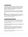
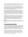
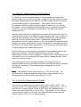
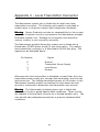
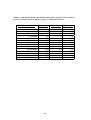
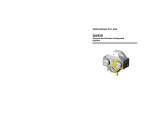
1
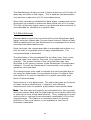
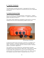
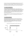
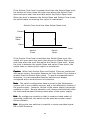
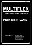
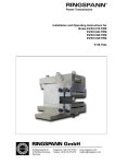
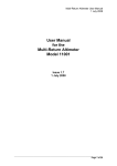
Sensor Products Mainstream Portable Flowmeter for Open Channels and Part-filled Pipes User Manual Doc: SP-030429 Warranty Sensor Products warrants that the Mainstream portable flowmeter is free from defects in material and workmanship and operates substantially as described in this manual. If, during the warranty period specified below, the Mainstream flowmeter is shown to the reasonable satisfaction of Sensor Products to be faulty and not to operate substantially as described in this manual, Sensor Products will repair or replace the flowmeter. Sensor Products will not be responsible for any failure of the Mainstream flowmeter caused by incorrect installation or extreme operating conditions and will not in any event be liable for any loss, consequential or otherwise, caused by any error, defect, or failure of the Mainstream flowmeter, howsoever arising, including but not limited to loss of use, loss of data, loss of profit or loss of contract. The warranty period is 12 months from the date of shipment. Contents 1. Overview 1.1 1.2 1.3 1 Physical Description 1 1.1.1 1.1.2 1.1.3 1.1.4 1 2 3 4 System Unit Velocity Probe Level Transmitter Mainstream Communicator Operating Principle 4 1.2.1 1.2.2 1.2.3 1.2.4 4 5 6 7 Liquid Level Measurement Flow Cross-sectional Area Calculation Velocity Measurement Flow Rate and Quantity Calculation Measurement Outputs 7 2. Power, Level and Velocity Connections 9 2.1 Physical Connections 2.2 Power Supplies 10 2.2.1 Internal Rechargeable Battery Pack 2.2.2 External 12 Volt Power Supply 2.2.3 External 24 Volt Power Supply 10 11 11 2.3 Level Transmitter 12 2.3 Velocity Probe 13 9 3. Flowmeter Configuration 14 3.1 Serial Port Baud Rate 14 3.2 Site Data Record 15 3.3 Pipe/Channel Section Definition 15 i 3.4 3.5 3.6 Measurement Configuration 16 3.4.1 Measurement Mode 3.4.2 Measurement Interval 16 16 Level Measurement Configuration 17 3.5.1 3.5.2 3.5.3 3.5.4 18 18 18 18 Level Level Level Level Measurement Mode Offset Sensor Warm-Up Time Signal ADC Parameters Velocity Measurement Configuration 19 3.6.1 3.6.2 3.6.3 3.6.4 3.6.5 3.6.6 3.6.7 3.6.8 3.6.9 3.6.10 3.6.11 3.6.12 19 20 20 20 20 21 21 21 21 22 22 22 Velocity Measurement Mode Velocity Range Measurement Response Time Histogram Interpretation Method Velocity Probe Scale Factor Signal Quality to Fail Bi-Directional Measurement Energy Distribution Histogram Averaging Doppler Signal Sample Rate Number of Records per Measurement Noise Suppression 4. Liquid Crystal Display 23 4.1 Display Configuration 23 4.2 Measurement Units 23 5. Data Logger 25 5.1 Real Time Clock 25 5.2 Data Logger Configuration 26 5.2.1 Recording Interval 5.2.2 Daily Records 26 26 5.3 Data Retrieval 27 5.4 Deleting Logged Data 28 ii 6. Switch Outputs 29 6.1 Switch Electrical Data 29 6.2 Switch Configuration 30 6.2.1 Switch Hysterisis 6.2.2 Flow Proportional Pulses 30 32 Switch Monitoring and Test 32 6.3 Appendix 1 - Flowmeter Specification 33 Appendix 2 - Velocity Probe Mounting 36 Appendix 3 - Level Transmitter Connector 37 Appendix 4 - Auxiliary Connector 38 Appendix 5 - Battery Endurance 39 iii 1. Overview The Mainstream portable flowmeter is designed to measure the flow of liquids in open channels and part-filled pipes. Applications include sewer and effluent flow monitoring, river and stream flow measurement, waste water treatment, industrial flowmetering and irrigation systems. 1.1 Physical Description The flowmeter consists of a portable system unit, a velocity probe and level transmitter, and Mainstream Communicator PC software. 1.1.1 System Unit The Mainstream portable flowmeter system unit is constructed from a rugged, high impact structural copolymer. The system unit is water-tight and contains level transmitter and velocity sensor control and interface circuits, a flow computer, LCD, data logger, two opto-isolated switch outputs, and a serial communications interface. Dimensions of the system unit are 270 mm wide by 250 mm deep by 120 mm high. The system unit weighs approximately 2 kg. The system unit may optionally be supplied fitted with an internal rechargeable battery pack. The internal battery increases the total weight to 3 kg. 1 Opening the hinged lid of the system unit gives access to the flowmeter ON/OFF switch, the serial communications connector, and the liquid crystal display. The velocity probe and level transmitter are attached via watertight connectors located at the rear of the system unit. An additional water-tight connector is provided at the rear of the system unit to connect external power supplies and to interface to the two opto-coupled switch outputs. This auxiliary connector is also used to charge the optional internal battery pack. Each Mainstream portable flowmeter system unit is identified by a unique serial number of the form OCFM7XXX. This serial number should be quoted in any communication relating to the flowmeter. 1.1.2 Velocity Probe The velocity probe consists of a streamlined injection moulded µPVC body 105 mm long by 50 mm wide by 20 mm high. The probe operates immersed in the flowing liquid. At the front of the probe facing into the flow are two 'eyes' which use ultrasound to interrogate the moving liquid. The probe body contains the electronic circuits which generate this ultrasound and process the ultrasonic signals. The maximum working temperature of the probe is 85°C. The velocity probe is connected to the Mainstream system unit via a reinforced cable. This cable supplies power to the velocity probe and carries data back to the system unit. 2 The velocity probe cable is supplied fitted with an water-tight connector which mates with the velocity connector at the rear of the system unit. The standard velocity probe cable length is 10 metres. Probes can be supplied with longer cable lengths up to a maximum of 500 metres. For intrinsically safe applications, a velocity probe certified as follows is available EEx ia IIC T5 (Tamb -20°C to +40°C) EEx ia IIC T4 (Tamb -20°C to +80°C) 1.1.3 Level Transmitter Mainstream flowmeters can operate with any level transmitter capable of generating a 4:20 mA signal. In many applications, the liquid level is determined by means of a pressure transmitter which uses a vented cable to provide an atmospheric reference. Pressure transmitters supplied by Sensor Products are fitted with a water repellent breather and a water-tight connector which mates with the level connector at the rear of the system unit. An optional adapter is available which attaches the pressure transmitter to a mounting point at the rear of the velocity probe. This combines the pressure transmitter and velocity probe into an easy-to-install level-velocity sensor. Mainstream flowmeters can also be supplied with level transmitters based on other technologies such as through-air ultrasonics, through-liquid ultrasonics, or bubblers. 3 1.1.4 Mainstream Communicator The Mainstream portable system unit has a serial port connector located inside the hinged lid. This serial port links the Mainstream to a local PC using the communications cable supplied with the flowmeter. Each Mainstream portable flowmeter is supplied with a Mainstream Communicator software package that operates on the PC platform under MS Windows 98/Me/2000/XP. This software is an integral part of the Mainstream product and enables the user to exploit all the features of the Mainstream flowmeter. Mainstream Communicator provides functions for flow measurement system configuration, pipe/channel cross-section definition, calibration of level transmitters, flow measurement diagnostics, configuration and testing of the flowmeter outputs, display of flow measurement data in real time, and retrieval of data from the Mainstream logger. For complete details refer to the Mainstream Communicator User Guide. 1.2 Operating Principle Mainstream makes separate measurements of the liquid level and flow velocity. These are combined with a description of the geometry of the pipe or channel to give the liquid flow rate. 1.2.1 Liquid Level Measurement Any form of level transmitter that supplies a 4:20 mA output signal may be employed. The Mainstream system unit applies power to the level transmitter, and after a user defined time delay, measures the 4:20 mA signal current flowing through the transmitter. This current is converted into a liquid level measurement. The conversion process uses level transmitter calibration data held in non-volatile memory within the Mainstream system unit. The calibration data is in the form of a table that relates the level transmitter loop current to the liquid level. The table may contain up to 31 points. Automatic interpolation between the calibration points is effective in removing any non-linearity inherent in the level transmitter. 4 1.2.2 Flow Cross-sectional Area Calculation The flow cross-sectional area is deduced from the liquid level measurement using a description of the pipe or channel crosssection held in non-volatile memory within the Mainstream system unit. Liquid Level Cross-sectional Area The description of the pipe or channel cross-section may be entered graphically using the Mainstream Communicator software supplied with the flowmeter. Typically this procedure involves selecting and sizing a pre-defined pipe section – circular, elliptical or rectangular, or channel section - rectangular, trapeziodal or semicircular. Alternatively, the pipe or channel cross-section may be entered using a 'freehand' drawing tool using data from a site survey. The drawing of the pipe or channel cross-section is stored in nonvolatile memory in the Mainstream system unit and can be recovered, viewed and modified. The drawing is automatically converted into a level-to-area conversion table which is also stored in non-volatile memory. As an alternative to graphical entry of the pipe/channel crosssection, the level-to-area conversion table may be read directly from a file supplied by the user in spreadsheet format. Liquid level measurements are converted into cross-sectional area values by reference to the stored level-to-area conversion table. For details of the software tools for pipe/channel design and editing see the Mainstream Communicator User Guide. 5 1.2.3 Velocity Measurement The Mainstream velocity probe transmits ultrasound into the flowing liquid to create a zone of inspection. Bubbles and solid particles carried through this zone by the flow, even when present in only minute quantities, reflect ultrasound back to the probe. Liquid Flow Zone of Inspection Velocity Probe Enhanced Phase Coherence Processing (patents pending) is used to analyse the received ultrasound. This produces a signal quality measurement and a velocity histogram. The signal quality is the percentage of the ultrasound signal that contains verified velocity information. A high signal quality confirms the integrity of the measurement. The velocity histogram shows the relative amounts of the ultrasound signal corresponding to each flow velocity. Illustrated below is a histogram for a flow containing velocities ranging from around 0.6 m/S to in excess of 1.5 m/S. Histogram Mean -3 -2 -1 Histogram Peak 0 1 2 3 Flow Velocity (m/S) The velocity and direction of the flow are determined from the velocity histogram using one of two methods - Histogram Mean or Histogram Peak. 6 Histogram Mean is the normal operating mode of the Mainstream flowmeter. In this mode the flow velocity is computed from the moment of the histogram. This corresponds to calculating the weighted mean of all the velocities observed. Histogram Peak determines the velocity corresponding to the maximum value of the velocity histogram. This is the most common of all the velocities observed. 1.2.4 Flow Rate and Quantity Calculation The liqiud flow rate is determined by multiplying together the measured velocity and the effective flow cross-sectional area deduced from the liquid level measurement. Mainstream also calculates two flow quantities - the quantity in the last hour and the total quantity. The quantity in the last hour is continuously updated by integrating the measured flow rate. Note: If the flow rate is negative, because the measured velocity is negative, the total quantity remains unchanged. Every hour, on the hour, the hour quantity value is added to the total quantity and the quantity in the last hour is reset to zero. 1.3 Measurement Outputs The Mainstream portable flowmeter is equipped with several output systems to make use of the measurement data. The integral liquid crystal display, accessed by opening the hinged lid of the system unit, gives a review of all the measurement data – liquid level, flow cross-sectional area, signal quality, flow velocity, flow rate, flow quantity in last hour, and total flow quantity. More details of the LCD are given in section 4 of this User Manual. All the measurements can be accessed and displayed in real-time on a PC connected to the Mainstream flowmeter serial port. See the Mainstream Communicator User Guide for details of this feature. The built-in data logger records liquid level, velocity and flow rate information. Details of the data logger are given in section 5 of this User Manual. Recorded data may be retrieved to archive or for further processing using the Mainstream Communicator software. 7 See the Mainstream Communicator User Guide for further information. The Mainstream portable flowmeter has two opto-isolated switch outputs which may be configured to control external equipment such as pumps or samplers, or to activate alarms. Configuration and operation of the switches is described in detail in section 6 of this User Manual. 8 2. Power, Level and Velocity Connections To operate the Mainstream portable flowmeter, a suitable power supply must be provided, and the level transmitter and velocity probe must be connected to the Mainstream system unit. This section describes these electrical connections and their specifications. 2.1 Physical Connections Three connectors are located at the rear of the Mainstream portable system unit. These connectors are designated the Level connector, Velocity connector and Auxiliary connector. Level Connector Velocity Connector Auxiliary Connector With the exception of the serial communications interface, all electrical connections to the Mainstream portable system unit are made via these three connectors. Note: Note In order to maintain the integrity of the connectors, the sealing cap should be fitted whenever a connector is not in use. 9 2.2 Power Supplies The Mainstream portable flowmeter system unit may be powered by an internal rechargeable battery pack supplied as a factory fitted option, or by connection to a suitable external power source. The external power source may be a nominal 12V or 24V supply. 2.2.1 Internal Rechargeable Battery Pack The Mainstream portable flowmeter system unit may be supplied with a factory fitted internal rechargeable battery pack. The internal battery pack includes battery charger and power management hardware and has no user serviceable parts. The battery technology is NiMH and the battery capacity is nominally 4 Ah. Battery endurance for various applications may be calculated using the data given in Appendix 5. A mains powered battery charger adapter is supplied with the Mainstream portable system unit. The battery charger adapter mains input is via an IEC connector. The charger adapter accepts AC inputs from 100 to 240 volts at 50 to 60 Hz. The battery charger connects to the Mainstream portable flowmeter system unit via the Auxiliary connector. The battery supervisor circuit inside the internal battery pack controls the charging current and the duration of the charging process. During the battery charging process an LED inside the Mainstream ON/OFF switch flashes approximately once per second. The LED remains ON continuously to indicate charge complete. The charging time depends on the initial state of the battery and is a maximum of 14 hours. The life expectancy of the battery pack is in excess of 100 charge/discharge cycles. Hint: Hint The internal battery may be charged whilst the Mainstream flowmeter is operating and the battery charger may be left permanently connected to the Mainstream to maintain the battery in a fully charged condition. In this configuration the Mainstream flowmeter behaves as a mains powered device with built-in protection against long-term power failure. 10 2.2.2 External 12 Volt Power Supply The Mainstream portable flowmeter can be operated from an external 12 volt power source. Typically this power source might be a rechargeable battery. A 12V power supply cable which mates with the Auxiliary connector is available from Sensor Products. Conductor identification is provided with the cable. Information to enable users to construct custom power supply cables is provided in Appendix 4. In normal operation, the maximum current drain from the external 12V power supply is 50 mA. When the flowmeter is not making measurements, the current drain falls to below 1 mA. Endurance data for various battery Ah ratings is given in Appendix 5. The Mainstream system unit is protected internally against reverse power supply connection. In addition, applying a voltage in excess of 16 volts to the 12 volt power external power input will trigger an internal fuse within the Mainstream system unit. This fuse is selfresetting. Removing the over-voltage will restore normal operation. Caution: Caution The user should take adequate precautions to prevent the application of excessive voltages to the 12V power supply input. Failure to observe this precaution may result in permanent damage to the Mainstream portable system unit. 2.2.3 External 24 Volt Power Supply The Mainstream portable flowmeter can be operated from an external 24 volt power source. Typically this power source might be an industrial instrumentation power supply. A 24V power supply cable which mates with the Auxiliary connector is available from Sensor Products. Conductor identification is provided with the cable. Information to enable users to construct custom power supply cables is provided in Appendix 3. In normal operation, the maximum current drain from the external 24V power supply is approximately 60 mA. When the flowmeter is not making measurements, the current drain falls to around 10 mA. 11 The Mainstream system unit is protected internally against reverse power supply connection. In addition, applying a voltage in excess of 30 volts to the 24 volt external power input will trigger an internal fuse within the Mainstream system unit. This fuse is selfresetting. Removing the over-voltage will restore normal operation. Caution: Caution The user should take adequate precautions to prevent the application of excessive voltages to the 24V power supply input. Failure to observe this precaution may result in permanent damage to the Mainstream portable system unit. Hint: Hint If both 24V and 12V power supplies are connected to the Mainstream portable system unit, current is only drawn from the 24V supply. Failure of the 24V supply will result in a transparent fall-back to 12V operation. Thus, uninterruptable measurement operation can readily be obtained by using a 24V system supply combined with a back-up battery connected to the 12V power input. 2.3 Level Transmitter The Mainstream system unit is fitted with a level transmitter connector. Level transmitters supplied by Sensor Products are fitted with a mating connector. This connector is polarised so that it will only fit the level transmitter connector. For users wishing to construct custom level transmitter interfaces, details of the mating connector and pin specifications are given in Appendix 3. In operation, the Mainstream portable system unit delivers approximately 10.5 volts, current limited to less than 30 mA, to the level transmitter via the level source conductor. After a predetermined time (the level transmitter warm-up time), which is set using the Configure Level function of the Mainstream Communicator software, the Mainstream measures the current flowing through the level transmitter into the level sense conductor. This current is returned to the power supply negative rail via a resistance of nominally 10 ohms. The negative supply rail is accessible as the level ground conductor of the level transmitter connector. Caution: Caution The Mainstream portable system unit is fitted with protection circuits to guard against fault conditions. These circuits are capable of sinking fault currents for a limited duration only. The user should take adequate precautions to prevent sustained fault conditions. 12 2.4 Velocity Probe The Mainstream system unit is fitted with a velocity probe connector. All Mainstream portable velocity probes supplied by Sensor Products are fitted with a mating connector. This connector is polarised so that it will only fit the velocity probe connector. In operation, the Mainstream portable system unit delivers power to the velocity probe via the velocity probe connector. The velocity probe power supply is current limited to 45 mA to prevent excessive power consumption and possible damage to the Mainstream system unit during fault (e.g. short circuit) conditions. The Mainstream portable also incorporates protection circuits for the flow data signals returned from the velocity probe to the system unit via the velocity probe connector. Note: Users are strongly discouraged from making custom velocity probe cables. Incorrect cable construction may result in poor measurement performance or, in extreme cases, damage to the system unit or velocity probe. 13 3. Flowmeter Configuration The Mainstream portable flowmeter is extremely versatile and can be configured for a wide variety of measurement applications. The configuration process consists of loading configuration data into the Mainstream system unit using the appropriate functions provided by the Mainstream Communicator software. A brief explanation of some key flowmeter configuration parameters and their effect on flowmeter operation is given here. Refer to the Mainstream Communicator user guide for details of the procedures used to set these configuration parameters. Note: Note All configuration data is stored in non-volatile memory in the Mainstream system unit. The configuration is not affected by failure of the power supply. Operation resumes automatically when the power supply is restored. 3.1 Serial Port Baud Rate The speed of serial data communication between the Mainstream system unit and a local PC is controlled by the Mainstream baud rate. This can be set at 300, 600, 1200, 2400, 4800 or 9600. For convenience, the highest speed (9600) is normally chosen. The baud rate is set using the Set Baud Rate function of the Mainstream Communicator software. This displays the present baud rate setting and permits the user to alter this setting. Applying the new setting takes immediate effect and sets the communication speed for all subsequent exchanges of data. Note: Note It is not normally necessary to know what baud baud rate the Mainstream system unit is configured to use. The Mainstream Communicator PC software has an Automatic feature which will search through all possible baud rates until a connection is made. Caution: Caution If the Mainstream serial port is connected to the PC via a modem, changing the baud rate may render the Mainstream inaccessible. A local connection to the Mainstream will be required to restore the original baud rate. 14 3.2 Site Data Record The Mainstream flowmeter has a feature which stores a description of the measurement site in the Mainstream system unit memory. The fields are site name, site reference, site location, pipe/channel description, contact details and comments. The site data may be viewed and modified using the Edit Site Data function of the Mainstream Communicator software. Although not essential for operation, the site data is embedded in the PC data files created by all current versions of the Mainstream Communicator software and is useful as a tag identifying the data source. Note: Note Early versions of the Mainstream Communicator software use the site data memory in the Mainstream system unit to contain a short (200 character) user defined message. This note pad may be viewed and modified using the Edit NotePad function of the Mainstream Communicator software. 3.3 Pipe/Channel Section Definition The Mainstream flowmeter uses a description of the pipe/channel geometry to determine the flow cross-sectional area from liquid level measurements (see section 1.2.2). A proper pipe or channel cross-section is essential for correct flow rate, hour quantity and total quantity calculations. The pipe/channel cross-section data is normally provided from a site survey and used to configure the flowmeter prior to installation (see comment in section 5.2). The Mainstream Communicator functions Edit Pipe Cross-section and Edit Channel Cross-section provide an intuitive graphical interface for selecting and sizing standard cross-sections or, if a standard cross-section is not appropriate, entering a 'freehand' cross-section using site survey data. The pipe or channel cross-section may also be defined by numerical data presented in spreadsheet format. 15 3.4 Measurement Configuration The measurement configuration determines which parameters are to be measured and at what intervals. The configuration is set using the Configure Measurements function of the Mainstream Communicator software. 3.4.1 Measurement Mode The measurement mode may be OFF, Level Only, Velocity Only, or Level and Velocity. When the measurement mode is OFF, the system is in sleep mode with no measurement taking place and power consumption minimised. Note: Note The ON/OFF switch on the Mainstream portable system unit overides the measurement mode. Switching OFF forces the processor into a power saving sleep mode. Switching ON activates the configured measurement mode. Thus, the measurement mode OFF configuration option is rarely used. The Level Only and Velocity Only measurement modes are provided for applications where measurement of only one parameter is required. In the Level Only mode the Mainstream behaves as a level recorder for applications such as river monitoring. In the Velocity Only mode the Mainstream behaves as a velocity recorder which may be used for applications such as flow measurement in full pipes or to study residence times. For normal area-velocity flow measurement, both level and velocity measurements are required and the measurement mode must be set to Level and Velocity. Note: Note When the measurement mode is switched from OFF or Level Only to Velocity Only or Level and Velocity (i.e whenever velocity measurement is activated) the velocity measurement is set to operate in the Histogram Mean mode (see section 3.6.4). 3.4.2 Measurement Interval The measurement interval is the time elapsed between successive measurements of the liquid flow rate. This may be Continuous, 30 seconds, 1, 2, 3, 5, 6, 10, 12, 15, 20, 30 or 60 minutes. 16 Except when operating in the Continuous measurement mode, each measurement is recorded by the data logger. Thus, the recording interval is normally the same as the measurement interval. For most applications of the Mainstream portable flowmeter, where power is derived from a battery, the measurement interval will be a compromise between the need to make frequent measurements, thus ensuring a complete data record, and the need to conserve power in order to extend the battery life. Power consumption depends on the measurement interval because the Mainstream lapses into a low power sleep mode between measurements. Increasing the measurement interval conserves power but gives a slower response to changes in flow conditions. The battery endurance data provided in Appendix 5 should be used as a guide to the selection of battery capacity and measurement interval. In applications where power economy is not a consideration (e.g. if the Mainstream is powered from an industrial instrumentation power supply) the measurement interval may be set to Continuous. Continuous measurement means that a new measurement commences as soon as the previous measurement is complete. Typically this results in a new measurement every 10 to 15 seconds. Note: Note When the measurement interval is set to Continuous, the data recording rate must be set independently (see section 5 - Data Logger). 3.5 Level Measurement Configuration To make a level measurement, the Mainstream activates the power supply to the level transmitter. After waiting for a predetermined time interval, the level sensor warm-up time, Mainstream measures the current flowing through the level transmitter and then deactivates the power supply. The liquid level is then determined by reference to the level transmitter calibration data and the level offset. Level measurement configuration consists of setting the level measurement mode, the level offset, the level sensor warm-up time, and the level sensor analog to digital convertor parameters. These are set using the Configure Level Measurement function of the Mainstream Communicator software. 17 3.5.1 Level Measurement Mode The level measurement mode may be set to either OFF or ON. This interacts with the measurement mode (see section 3.4.1). Changing the level measurement mode does not affect the velocity measurement mode. Thus, if the level measurement mode is set to OFF, the Mainstream measurement mode will be either OFF or Velocity Only. Conversely, if the level measurement mode is set to ON, the Mainstream measurement mode will be Level Only or Level and Velocity. 3.5.2 Level Offset The level offset is a user defined amount added to the level measurement determined by the Mainstream level transmitter. This compensates for imperfections in the installation so that the level indicated by the Mainstream is always the true height of the liquid surface above the zero level datum of the pipe or channel. The level offset may be either negative or positive. Usually the level sensor is located above the pipe/channel datum and the level offset is a small positive value. 3.5.3 Level Sensor Warm-Up Time The level sensor warm-up time is the time delay between applying power to the level transmitter and taking a level measurement. Thus, the warm-up time must be set to a value greater than the stabilisation time of the level transmitter. A small warm-up time conserves power but requires a rapid level transmitter response. 3.5.4 Level Signal ADC Parameters The level signal ADC configuration consists of three parameters auto-zero time, integration time and de-integrate clock period. Under normal circumstances these parameters should be left at their factory settings. If these values are changed, re-calibration of the level transmitter will be required. If the level signal ADC configuration is changed accidentally, the Mainstream Communicator software provides a Defaults function which will restore the values to their factory settings. 18 3.6 Velocity Measurement Configuration To make a velocity measurement the Mainstream activates the power supply to the velocity probe. Signals from the velocity probe are then sampled and recorded by the Mainstream and the velocity probe power supply is deactivated. The signal record is then processed and the resulting velocity data is added to the velocity histogram. After repeating this procedure a pre-defined number of times the velocity histogram is analysed to provide the velocity measurement. Velocity measurement configuration consists of setting the velocity measurement mode, the Doppler signal sample rate, the number of records per measurement, the method of histogram interpretation, and the velocity probe scale factor. Additional configuration parameters are the signal quality to fail, bi-directional measurement status, an energy distribution switch, a histogram averaging switch, and the noise suppression parameter. The purpose and significance of each parameter is discussed below. All the velocity measurement configuration parameters may be set using the Configure Velocity Measurement function of the Mainstream Communicator software. Under most circumstances the user need only be concerned with the velocity measurement mode and the velocity range. The Mainstream Communicator software Configure Velocity Measurement function provides a default mechanism which restores the factory settings. These settings are adequate for most applications. Note: Note The default probe scale factor is 0.736 (mm/S)/Hz. For accurate flow measurement the scale factor appropriate to the velocity probe must be used (see section 3.6.5). 3.6.1 Velocity Measurement Mode The velocity measurement mode may be set to ON or OFF. This interacts with the measurement configuration (see section 3.4). If the velocity measurement mode is OFF then the measurement mode may be either OFF or Level Only. Conversely, if the velocity measurement mode is ON then the measurement mode may be either Velocity Only or Level and Velocity. 19 3.6.2 Velocity Range The velocity range setting determines the maximum flow velocity that can be measured. The turndown ratio is nominally 100:1. In practise, velocities well below the minimum can usually be measured although the signal quality and accuracy may be impaired. The velocity range setting is an indirect method of selecting the Doppler signal sample rate (see section 3.6.10). 3.6.3 Measurement Response Time The measurement response time is the time that the Mainstream requires to make a flow rate measurement. Rapidly varying flows require a short response time. For slowly changing flows a longer response time may be appropriate. The measurement response time setting is an indirect method of selecting the Number of Records per Measurement (see section 3.6.11). Increasing the response time uses more Doppler signal information and therefore gives a higher velocity measurement repeatability. However, this improved repeatability is obtained at the expense of increased power consumption. 3.6.4 Histogram Interpretation Method The method used to interpret the velocity histogram generated by the Mainstream system unit may be either Histogram Mean or Histogram Peak. See section 1.2.3 for an explanation of these methods. For normal operation use Histogram Mean. 3.6.5 Velocity Probe Scale Factor The probe scale factor translates the Doppler frequency data generated by the Enhanced Phase Coherence Processing alogorithm into the flow velocity. The probe scale factor is fixed at manufacture. The normal probe scale factor is 0.736 (mm/S)/Hz. In special circumstances velocity probes with different scale factors may be supplied. For accurate flow measurement always use the scale factor appropriate to the probe. 20 Note: Note The probe scale factor is only valid for flowmeter operation in aqueous liquids. Consult Sensor Products for other applications. 3.6.6 Signal Quality to Fail The signal quality to fail is the value of the measured ultrasound signal quality (see section 1.2.3) below which it is considered unsafe to determine the flow velocity from the velocity histogram data. When the signal quality falls below the signal quality to fail, the Mainstream flowmeter gives the velocity measurement as zero. 3.6.7 Bi-Directional Measurement Bi-directional measurement may be set to ON or OFF. In normal operation this parameter is set to ON. When set to OFF, the measured flow velocity will always appear as positive, regardless of the true direction of the flow. 3.6.8 Energy Distribution Energy distribution may be set to either ON or OFF. The normal setting is OFF. When energy distribution is OFF, all the data used to determine the flow velocity is acquired at the start of the measurement interval. The flowmeter then goes into sleep mode to conserve power. The velocity histogram is therefore a ‘snap-shot’ representing only the flow conditions at the start of the measurement interval. When energy distribution is ON, the data records used to determine the flow velocity (see section 3.6.11) are acquired at approximately equal intervals throughout the measurement interval (see section 3.4.2) so that the velocity histogram represents the activity of the flow during the entire measurement interval. If the measurement interval is Continuous (see section 3.4.2) the energy distribution setting has no effect. 3.6.9 Histogram Averaging Histogram averaging may be set to either ON or OFF. The normal setting is OFF. 21 When histogram averaging is OFF, each velocity measurement is based only on information accumulated during the latest measurement interval. When histogram averaging is ON, part of the information from the previous measurement interval is retained and combined with new information accumulated during the measurement period. This has the effect of smoothing changes in the measurement and can be used to improve measurement repeatability whilst conserving battery power. 3.6.10 Doppler Signal Sample Rate The Doppler Signal Sample Rate governs the digitisation of data from the velocity probe. The default value is 28.8 kHz which is adequate for most measurements. This is the value obtained by selecting the default velocity range (see section 3.6.2). Sensor Products may advise different settings to optimise the Mainstream flowmeter for specific applications. 3.6.11 Number of Records per Measurement The number of records per measurement controls the quantity of data processed to perform each velocity measurement. Increasing the value will improve measurement repeatability at the expense of a slower response to flow changes and higher power consumption. Reducing the value improves response time and decreases power consumption but gives poorer measurement repeatability. The Mainstream Communicator software will automatically provide appropriate settings for most applications via the Measurement Response Time (see section 3.6.3). 3.6.12 Noise Suppression The Enhanced Phase Coherence Processing technique uses a noise suppression figure to optimise flowmeter performance. The default value is 16. Consult Sensor Products for advice on other settings for specialist applications. 22 4. Liquid Crystal Display The Mainstream portable flowmeter is fitted with a two line by sixteen character liquid crystal display (LCD) which is viewed through a window in the system unit front panel. The LCD is light activated. Opening the hinged lid of the system unit will start the LCD. The LCD powers down approximately ten seconds after closing the system unit lid. 4.1 Display Configuration The LCD display may be set to show the Mainstream ID number, date and time, plus a sequence of displays consisting of any combination of the following parameters - liquid level, flow crosssectional area, ultrasound signal quality, flow velocity, flow rate, quantity in last hour and total quantity. The display cycles continuously through the programmed sequence with each parameter visible for approximately 2.5 seconds. The LCD may also be configured as either ON or OFF. Since the LCD in the Mainstream portable is light activated and only operates when the system unit lid is opened, the normal LCD configuration is ON. When configured as OFF, the LCD and associated circuits are completely disabled for power saving. Configuration of the LCD is performed using the Configure LCD function of the Mainstream Communicator software. 4.2 Measurement Units The engineering units used by the LCD display are user selectable. The same set of engineering units is used by the Mainstream Communicator PC software for all flowmeter configuration and measurement display functions, and in retrieved data files. The measurement units are selected using the Configure Measurement Units function of the Mainstream Communicator software. Changing the measurement units has no effect on any configuration or other data stored within the Mainstream system unit. Conversion between units is automatic and any mixture of units may be employed. 23 The Mainstream portable flowmeter can be configured to use any combination of the engineering units tabulated below Parameter Liquid Level Cross-sectional Area Signal Quality Flow Velocity Flow Rate Flow Quantity Measurement Unit mm, m, in, ft m2, cm2, mm2, in2, ft2 % mm/S, m/S, in/S, ft/S, ft/min l/S, m3/S, ft3/S, imp gall/S, US gall/S, l/min, m3/min, ft3/min, imp gall/min, US gall/min, m3/h, ft3/h, m3/day, k.m3/day l, m3, k.m3, ft3, imp gall, US gall 24 5. Data Logger The Mainstream portable flowmeter system unit contains a data logger which records the level and velocity measurements. The measurements are stored in a compressed form which optimises memory utilisation. The memory capacity is 224 k-bytes. This gives a typical logger capacity of approximately 250,000 readings, equivalent to more than six months of level and velocity data recorded at 2 minute intervals. If the measurement mode (see section 3.4.1) is Level Only or Velocity Only, the logger capacity is increased by storing only the active measurement. The measurements are stored in data records. A new data record is initiated each time the Mainstream is powered up or the internal clock is reset, and whenever the measurement mode, measurement interval or recording interval is changed (see section 3.4). New data records are also started automatically when the record size reaches 16 k-bytes. To simplify access to the stored data, a new record may optionally be started at a fixed time each day. Associated with each data record is a record descriptor. This record descriptor contains the record start date, start time, recording interval, and the measurement mode - Level Only, Velocity Only, or Level and Velocity. The maximum number of record descriptors (hence the maximum number of data records) is 100. The data logger operates in continuous mode. When the logger memory is full, or the maximum number of data records is exceeded, the logger deletes the oldest data record and uses the memory released to record new measurement data. 5.1 Real Time Clock The Mainstream system unit contains a real time clock. This provides the time reference for the data logger and triggers the transfer of measurements into the data logger memory. The time and date of the real time clock are set using the Set Date/Time function of the Mainstream Communicator software. This synchronises the Mainstream system clock to the PC. 25 Note: Note Setting the real time clock interacts with the data logger by generating a new data record descriptor. If the Mainstream portable system unit is fitted with an internal battery pack (see section 2.2.1), the real time clock will operate almost indefinitely. Without an internal battery pack, removal of the Mainstream power supply results in operation of the real time clock from a back-up battery within the Mainstream system unit. When fully charged, this battery will maintain operation of the real time clock for a minimum of 48 hours. Note: Note The back-up battery is charged automatically whenever the Mainstream system unit is connected to a 12V or 24V power supply. To fully charge the back-up battery requires the Mainstream system unit to be continuously powered for a minimum of 24 hours. 5.2 Data Logger Configuration Data logger configuration consists of selecting the logging interval and enabling or disabling daily records. The data logger configuration is set using the Configure Data Logger function of the Mainstream Communicator software. This displays the recording interval and the daily record status and permits modification of these parameters. 5.2.1 Recording Interval The recording interval is the time elapsed between successive entries of data into the logger memory. If the measurement interval is not set to Continuous, the recording interval is always the same as the measurement interval (see section 3.4.2). If the measurement interval is set to Continuous, the recording interval may be set to 30 seconds, 1, 2, 3, 5, 6, 10, 12, 15, 20, 30 or 60 minutes. 5.2.2 Daily Records The daily records option can be enabled or disabled. When enabled, a new data record descriptor is created at a fixed time every day. The record start time may be selected from 00:00 to 23:00 hours in one hour increments. This simplifies access to recorded data on a date basis. 26 The disadvantage of daily records is that a maximum of 100 days of data may be stored in the logger. This is because the Mainstream only permits a maximum of 100 record descriptors. When daily records are disabled the data logger creates new record descriptors to maintain a maximum data record size of 16 k-bytes. This fully utilises the logger memory but prevents direct retrieval of recorded data by reference to a specific date. 5.3 Data Retrieval Selected data records may be retrieved from the Mainstream data logger using the Mainstream Communicator function Retrieve Data. Data is transferred from the Mainstream in compressed form which minimises the data transfer time. Once retrieved, the compressed data is expanded and written to a text file that is compatible with all major spreadsheets. The compressed data is discarded. The data fields of the spreadsheet file are date, time, level, crosssectional area, flow velocity, flow rate, hour quantity and total quantity. The precise format of the retrieved data may vary according to the version number of the Mainstream Communicator software. Consult the Mainstream Communicator user guide for specimen retrieved data. The measurement units used to express the retrieved data are as set using the Mainstream Communicator function Configure Units (see section 4.2) and are identified in a header preceding each block of retrieved data. Data retrieval is non-destructive. The same data may be retrieved as many times as desired and, if required, with different measurement units or updated pipe/channel cross-section data. Note: Note The flow rate and quantity are calculated from the recorded level and velocity data and the pipe/channel cross-section definition in place at the time of the data retrieval. Thus, changing the crosssection prior to retrieval forces automatic recalculation of the flow measurements. This feature is extremely useful if a precise definition of the cross-section is not available at the time of flowmeter installation. 27 5.4 Deleting Logged Data The Mainstream Communicator function Retrieve Data provides a Delete option which erases all data from the Mainstream data logger. It is not possible to selectively delete single data records. Caution: Caution Once the Delete option is activated all information held within the Mainstream data logger is permanently destroyed and can no longer be retrieved. 28 6. Switch Outputs The Mainstream portable flowmeter is equipped with two switch outputs that may be configured to operate devices such as samplers and alarms. 6.1 Switch Electrical Data The two switches are designated Switch 1 and Switch 2. Signals Switch 1A and Switch 1B relate to Switch 1. Signals Switch 2A and Switch 2B relate to Switch 2. The switch output signals are accessed via the Auxiliary connector located at the rear of the Mainstream portable system unit. Auxiliary Connector A cable that mates with the Auxiliary connector is available from Sensor Products. Conductor identification is provided with the cable. Information to enable users to construct custom interface cables is provided in Appendix 4. The switches are opto-isolated from the Mainstream portable flowmeter power supply and from each other. Each switch is rated at 50V ac/dc and is protected by a 100 mA self-resetting fuse located within the Mainstream portable system unit. When closed, the resistance across the switch is typically less then 10 ohm. 29 Caution: The user should take adequate precautions to prevent the transmission of high current pulses through the switches or the application of excessive voltages. Failure to observe this precaution may destroy both the switch protection circuits and the switches. 6.2 Switch Configuration The two switches operate independently. Each switch may be configured to react to the liquid level, ultrasound signal quality, flow velocity or volume flow rate with different Open and Close switching values (see section 6.2.1 - Switch Hysterisis). Each switch may also be configured to close for a 2.5 second interval to indicate the passage of a predetermined quantity of flow (see section 6.2.2 Flow Proportional Pulses). Switch configuration is performed using the Configure Switch 1 and Configure Switch 2 functions of the Mainstream Communicator software. 6.2.1 Switch Hysterisis Either switch may be configured to respond to the liquid level, ultrasound signal quality, flow velocity or volume flow rate using different Open and Close switching values. The effect of using different switch Open and switch Close values is to provide hysterisis. This is illustrated below for a switch configured to respond to the liquid level. Switch Close level greater than Switch Open level Closed Switch State Open Switch Open Switch Close 30 Level If the Switch Close level is greater level than the Switch Open level, the switch will close when the level rises above the Switch Close level and open when the level falls below the Switch Open level. When the level is between the Switch Open and Switch Close levels, the switch state on entering this region is maintained. Switch Close level less than Switch Open level Closed Switch State Open Level Switch Close Switch Open If the Switch Close level is less than the Switch Open level, the switch will open when the level rises above the Switch Open level and close when the level falls below the Switch Close level. When the level is between the switch Open and switch Close levels, the switch state on entering this region is maintained. Caution: Caution When both Switch Open and Switch Close are configured with equal values, the switch behaves as if the Switch Close value is greater than the Switch Open value. To avoid unexpected switch operation, it is recommended that the switches are always configured with a small amount of hysterisis. Note: Note The switch configuration data is stored in the Mainstream system unit in non-volatile memory and is not affected by failure of the power supply. However, failure of the power supply causes the switches to open. Normal operation will resume automatically after the first measurement following restoration of the power supply. Hint: Hint By configuring a switch so that it remains closed under all operating conditions, the switch can be used as a power supply failure indicator. Hint: Hint Wiring the two switches in parallel or series provides logical OR or AND functions. 31 6.2.2 Flow Proportional Pulses Each switch may be configured to close for 2.5 seconds to indicate the passage of a predetermined quantity of flow. The switch closure will occur within 2.5 seconds after the predetermined flow quantity is accumulated. Caution: Caution To ensure correct switch operation, the predetermined flow quantity must be greater than the quantity that can flow in any 5 second period. 6.3 Switch Monitoring and Test The Mainstream portable flowmeter has a switch monitor and test feature which is accessed using the Mainstream Communicator function Test Switches. This indicates the states of the two switches as determined by the Mainstream measurements and the switch configuration. The Test Switches function also enables the switch states to be modified as desired in order to test the functionality of the switches and any attached apparatus. It is not necessary to alter the switch configuration to perform this operation since the test function temporarily overrides normal switch operation. The test procedure does not disrupt the measurement process. Caution: Caution If the switch states are modified and 5 minutes has elapsed without any input from the user, the switch states will normally revert to those determined by the Mainstream measurements and the switch configuration. These same switch states will normally result when the switch test procedure is terminated. However, hysterisis may prevent the switches reverting to the states existing prior to the switch test, even though no change in the measurement has taken place. 32 Appendix 1 - Flowmeter Specification System Unit Water-tight high impact structural copolymer enclosure. Hinged lid to access ON/OFF switch, LCD and serial communications. Water-tight connectors for level transmitter, velocity probe and external power supplies and switch outputs. Dimensions 270 mm wide x 250 mm deep x 120 mm high. Weight 2 kg (3 kg with optional internal battery pack). Velocity Probe Streamlined µPVC moulding. Overall dimensions 105 mm long x 50 mm wide x 20 mm high. Operating temperature range 0°C to 85°C. Reinforced cable - standard length 10 m, maximum length 500m. Level Transmitter Stainless steel pressure transmitter with water resistant atmospheric reference. Standard measurement range 0-2 metres. Reinforced cable - standard length 10 m. Interface fully compatible with alternative level transmitters providing 4:20 mA signals. Power Supplies Optional 4 Ah internal battery pack with built-in charger and power management hardware. Universal charger adapter accepts 100 to 240 VAC at 50 to 60 Hz. 14 hour maximum charge time, 100 recharge cycles. External 12V dc input for battery powered applications. External 24V dc input (18 to 30V) at 60 mA maximum current for operation from industrial power supplies. Automatic power source selection for uninterruptable operation. 33 Display Large character LCD activated automatically by light sensor when system unit lid is opened. Display sequence is date and time plus user selection from level, flow cross-sectional area, signal quality, flow velocity, flow rate, quantity of flow in last hour and total flow quantity. Display configurable for most engineering units. Data Communications RS232 compatible serial port. Automatic error detection protocol. Windows 98/Me/2000/XP compatible Mainstream Communicator software supplied with every flowmeter. Software features flowmeter configuration, diagnostics, and real time measurement displays. Data Logger Integral data logger with recording rate configurable for 30 seconds, 1, 2, 3, 5, 6, 10, 12, 15, 20, 30 or 60 minute intervals. Optional daily records to simplify data access. Logger capacity approximately 250,000 measurements corresponding to more than 6 months data at 2 minute intervals. Data retrieval to spreadsheet compatible .CSV files. Switch Outputs Two opto-isolated switch outputs, each rated at 60V ac/dc and 100 mA maximum current and protected by internal self-resetting fuses. Switches independently programmable to open or close at user defined liquid level, signal quality, flow velocity or flow rate, or to generate flow proportional pulses with user defined quantity. 34 Measurement Performance Velocity measurement from less than 10 mm/S up to 5 m/S in both forward and reverse directions (subject to 100:1 turn-down ratio). Velocity resolution 1 mm/S. Guaranteed no zero offset or drift. Standard level measurement by pressure transmitter with range from 0 mm to 2 m. Other ranges available. Level resolution 1 mm. Conversion accuracy better than 0.1% of full scale. Flowmeter accuracy depends on installation and operating conditions. Flow measurement error typically less than 5%. 35 Appendix 2 - Velocity Probe Mounting For accurate and reliable flow measurement the velocity probe must be correctly sited and securely fixed in place. To mount the velocity probe, four brass inserts threaded M3 are located in the base of the probe body. These are used to attach the velocity probe to the installation hardware. The layout of these inserts is as shown below. 20 63 90 105 42 50 Note: Note The velocity probe cable must be securely fixed to ensure that no excessive loading is transferred to the probe mounting. 36 Appendix 3 - Level Transmitter Connector The Mainstream system unit is fitted with an eight way level transmitter connector. The following information is provided to enable users to construct custom level transmitter interfaces. Warning: Warning Sensor Products can take no responsibility for the correct operation of custom circuitry connected to the Mainstream portable flowmeter system unit. Damage to the system unit caused by custom circuitry is not covered by warranty. The Mainstream portable flowmeter system unit is fitted with a Hirschmann CA3GD panel socket (3-way plus earth). The mating level transmitter connector is a Hirschmann CA3LS free plug. The signals are as tabulated below Pin Number E 1 2 3 Signal Ground Transmitter Power Supply Level Sense Unused Whenever the level transmitter is activated, current flows from the transmitter power supply pin, through the transmitter, and into the level sense pin. The voltage developed across a 10R resistor in the Mainstream portable system connecting the level sense pin and ground is monitored to determine the transmitter loop current. Warning: Warning The Mainstream portable system unit is fitted with protection circuits to guard against fault conditions. These circuits are capable of sinking fault currents for a limited duration only. The user should take adequate precautions to prevent sustained fault conditions. 37 Appendix 4 - Auxiliary Connector The Mainstream system unit is fitted with an eight way auxiliary connector. The following information is provided to enable users to construct custom interfaces to the services provided via the auxiliary connector. Warning: Warning Sensor Products can take no responsibility for the correct operation of custom circuitry connected to the Mainstream portable flowmeter system unit. Damage to the system unit caused by custom circuitry is not covered by warranty. The Mainstream portable flowmeter system unit is fitted with a Hirschmann CA6LD panel plug (6-way plus earth). The mating auxiliary connector is a Hirschmann CA6LD free socket. The signals are as tabulated below Pin Number E 1 2 3 4 5 6 Signal Ground 12V Power Input 24V Power Input / Battery Charger Switch 1A Switch 1B Switch 2A Switch 2B Warning: Warning The Mainstream portable system unit is fitted with protection circuits to guard against fault conditions. These circuits are capable of tolerating fault conditions for a limited duration only. The user should take adequate precautions to prevent sustained fault conditions. 38 Appendix 5 - Battery Endurance Battery life depends on both the battery capacity and the flowmeter configuration and operating conditions. The following data is given for guidance only and is not guaranteed. Measurement Rate Continuous 30 seconds 1 minute 2 minutes 3 minutes 5 minutes 6 minutes 10 minutes 12 minutes 15 minutes 20 minutes 30 minutes 60 minutes Ah/day 0.650 0.280 0.152 0.091 0.071 0.054 0.050 0.042 0.040 0.038 0.036 0.034 0.032 Ah/week 4.49 1.96 1.07 0.64 0.50 0.38 0.35 0.30 0.28 0.27 0.25 0.24 0.22 Ah/month 18.0 7.8 4.3 2.6 2.0 1.5 1.4 1.2 1.1 1.1 1.0 1.0 0.9 To estimate the battery endurance, divide the battery Ah rating by the Ah rate from the table above using the appropriate flowmeter measurement rate. Note: Note Measurement is terminated when the battery voltage at the 12V input falls below 11.2V whilst delivering a 40 mA load current. For this reason low impedance power supply leads must be used and battery technologies producing flat load curves are preferred. Frequent use of the serial communication port, a level transmitter with a long warm-up time, exceptionally high flow velocities, and low signal quality, all increase the power demand and consequently reduce battery endurance. 39 Battery endurance data calculated using the nominal 4 Ah capacity of the optional internal battery pack is tabulated below. Measurement Rate Continuous 30 seconds 1 minute 2 minutes 3 minutes 5 minutes 6 minutes 10 minutes 12 minutes 15 minutes 20 minutes 30 minutes 60 minutes Endurance (days) 6 14 26 42 56 74 80 95 100 105 111 117 125 40 Endurance (weeks) 1 2 3 6 8 10 11 13 14 15 15 16 17 Endurance (months) 0.2 0.5 0.7 1.5 2.0 2.5 2.7 3.2 3.5 3.7 3.7 4.0 4.2