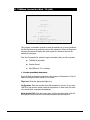
1
CTO Terminal User Manual Skyplan Services Ltd. Suite 104 7777 10th Street N.E. Calgary, Alberta, Canada T2E 8X2 Phone +403-275-2520 Fax +403-275-3877 Sita YYCSKXH Arinc YQFSKXH Aftn CYYCXXSK 1. Table of Content 1. Table of Content .................................................................................. i 2. Installation ........................................................................................2-1 Overview ................................................................................................... 2-1 Download/Install Software (via HTTP) .................................................... 2-1 Download/Install Software (via FTP) ....................................................... 2-1 3. Introduction ......................................................................................3-1 Overview ................................................................................................... 3-1 Menu Interface.......................................................................................... 3-2 Keyboard Mapping ................................................................................... 3-3 Printing ...................................................................................................... 3-4 System Maintenance ............................................................................... 3-5 4. Airports (110) ...................................................................................4-1 5. Alternate Airports (125) ...................................................................5-1 6. Enroute Stations (130).....................................................................6-5 7. Airline Parameter File (160) ............................................................7-1 8. MEL Codes (170) ............................................................................8-1 9. Personnel Flight Ops (175) .............................................................9-1 10. Aircraft Types (215) .......................................................................10-1 11. Aircraft Characteristics (220) .........................................................11-1 12. Routes – Citypair (305)..................................................................12-1 13. Entries – Oceanic (310) .................................................................13-1 14. Exits – Oceanic (315) ....................................................................14-1 15. Standard Instrument Departures / SID (320) ................................15-1 16. Standard Terminal Arrivals / STAR (325) .....................................16-1 17. Track Updates (330) ......................................................................17-1 18. Waypoints & Facilities (340) ..........................................................18-1 19. Airways Route Update (341) .........................................................19-1 20. Airway Direct Leg Update (342) ....................................................20-1 21. Airway Links (343) .........................................................................21-1 22. Station Addresses (375) ................................................................22-1 23. Flight Status (410) .........................................................................23-1 24. Flight Planning (415)......................................................................24-1 25. In-Flight Revision (416) .................................................................25-1 CTO TERMINAL – USER MANUAL I 26. Aircraft MEL/CDL Status (425)......................................................26-1 27. Analysis Request (430) .................................................................27-1 28. Minimum Time Track – Random (435) .........................................28-1 29. Minimum Time Track – Airways (436) ..........................................29-1 30. General Navigation Solutions (445) ..............................................30-1 31. TAS/Mach, Sunrise/Set, Wind - T/O (446) ...................................31-1 32. Conversions / Density Altitude (447).............................................32-1 33. Specific WXX/NOTAMs (460) .......................................................33-1 34. NOTAMs Company (466)..............................................................34-1 35. Work Summary Report (474) ........................................................35-1 36. Send Flight Papers (510) ..............................................................36-1 37. Weather Query System (660) .......................................................37-1 CTO TERMINAL – USER MANUAL II 2. Installation Overview CTO Terminal can be downloaded directly from Skyplan’s Support Web page or FTP server. The download process should take between 5-10 minutes depending on the reliability of your Internet Service Provider and your connection speed. The file is approximately 6 megabytes in size. CTO Terminal operates on any Internet connection that supports the TCP/IP protocol. A minimum bandwidth of 28,800 baud or higher is suggested for best performance. The minimum PC requirements are: Pentium 100 MB processor with 16 MB RAM 15” Monitor with SVGA Video card (minimum 800x600 resolution) Windows 95/98/ME/NT/2000/XP Download/Install Software (via HTTP) a) Log on to the Internet and go to your Web browser. b) Enter http://www.skyplan.com/support.asp. c) Click on CTO Terminal (Version x.x.x). d) Follow the on-screen instructions for downloading and installation. Download/Install Software (via FTP) 1) Log on to the Internet and go to your FTP client. 2) Enter ftp://www.skyplan.com/Downloads/. 3) Download/Save the file “CTOterminal.exe” to a temporary directory. 4) Run the file “CTOterminal.exe” from the temporary directory. 5) Follow the on-screen instructions for installation. CTO TERMINAL – USER MANUAL 2-1 3. Introduction Overview Welcome to CTO Terminal managed by Skyplan Services. Skyplan is a world leader in providing a full range of Flight Operations services. CTO Terminal has been developed to provide any aircraft operator interactive access to Skyplan’s Flight Planning and Weather Query systems. CTO Terminal represents the latest design technology available in the aviation industry. It has been developed around the most advanced computer programming tools and the most efficient and cost effective hardware systems available in the market. Just as important, CTO Terminal has been designed, developed and is maintained by a staff with extensive aviation Operations experience. Therefore, it has been designed to operate efficiently in a day-to-day operations environment as a support tool and not as a distraction to the operations staff. It has also been designed to be as user friendly as possible and requires minimal training to use. This manual is designed to assist in the day-to-day use of CTO Terminal. Any problems or service requirements should be directed to: Skyplan Operations Suite 104, 7777 10th Street N.E. Calgary, Alberta, Canada T2E 8X2 Telephone: SITA: ARINC: AFTN: E-MAIL: Website: (403) 275-2511 (Direct) (800) 661-9189 (US Toll Free) (403) 275-3911 (Fax) YYCSKXH YQFSKXH CYYCXXSK [email protected] www.skyplan.com No part of this manual may be reproduced, transmitted, transcribed, stored in a retrieval system or translated into any language in any form by any means without the written permission of Skyplan International Inc. CTO TERMINAL – USER MANUAL PAGE 3-1 Menu Interface Interactive access to Skyplan’s Flight Planning and Weather system is menu driven, meaning the User directs the system by selecting the desired program from a menu. [ABC AIRLINES] CYBERTRAC ONE "FOMS" - DISPATCH MENU {System: FOMS} -----------------------------------------------------------------------------DATABASE MAINTENANCE: -------------------110 - Airports 125 - Alternate Airports 160 - Airline Parameter File 220 - Aircraft Characteristics 305 310 315 320 325 330 375 - Routes - Citypair Entries - Oceanic Exits - Oceanic SIDS STARS Track Updates Station Addresses DISPATCH FUNCTIONS: -----------------410 - Flight Status 415 - Flight Planning 416 - In-Flight Revision 430 - Flight Analysis Request 435 - Minimum Time Track - Random 436 - Minimum Time Track - Airways 445 - General Navigation Solutions 446 - TAS/Mach, Sunrise, Wind-TO/LND 447 - Conversions / Density Altitude 460 - Specific WXX/Notams 474 - Work Summary Report 510 - Send Flight Papers 511 - Send Flight Papers via e-mail 660 - Weather Query System -----------------------------------------------------------------------------Enter "000" to LOGOUT of System Type Your Choice and Press {ENTER}: ... Each program is accessed by entering its corresponding menu number. All programs have been organized into menu groups according to function: 100 - Management 200 - Aircraft Maintenance 300 - Database Maintenance 400 - Dispatch 500 - Communications 600 - System Control CTO TERMINAL – USER MANUAL PAGE 3-2 Keyboard Mapping The following table summarizes the PC keyboard keys to use when interacting with Skyplan’s Flight Planning system: PC KEY EQUIVALENT TO DESCRIPTION Insert <Ctrl-I> To insert a line Delete <Ctrl-D> To Delete a line Home <Ctrl-X> To clear a field - wipes all characters in the field in preparation for a revised entry End <Ctrl-E> To save your Changes and proceed with the next option Page Up <Ctrl-B> To display the previous page/screen of Up a multi-page display Page Down <Ctrl-F> To display the next page/screen of Down a multi-page display Up/Down Arrows To display the Previous/Following record in the selected range F10 <Ctrl-R> To display a full page/screen of a multi-page display (Zoom In/Out) F12 ? + <Enter> To let the system retrieve and display possible field values (where allowed) <Enter> CTO TERMINAL – USER MANUAL Execute Command Option or move to next data field on the screen PAGE 3-3 Printing Whenever you select the Hardcopy (or Print) option, CTO Terminal will return the output to your screen using Pass-Thought Printing. You will then have the option to: View the output Save the output to your Local Hard Drive Print the output to your Printer Copy/Paste the output into another Windows program Example: Select the Hardcopy option to send the output to your screen: CTO TERMINAL – USER MANUAL PAGE 3-4 Once CTO Terminal has completed sending the Hardcopy output to your PC, the “Print Viewer” window will appear: From here, you have the option to (via the pull-down Menus or Toolbar icons): View the output Save the output to your Local Hard Drive Print the output to your Printer Copy/Paste the output into another Windows program System Maintenance At designated times during the day, the response time of the system may be slightly slowed for Weather/NOTAMs database maintenance. CTO TERMINAL – USER MANUAL PAGE 3-5 4. Airports (110) [XXS/uid] 110 AIRPORTS ------------------------------------------------------------------------------Station ICAO: .... ... .................... Country Code: .. .............................. Lat/Long/Var: ....... ........ ... --- Runway Data --Elevation...: ..... Number of.......: . NOTAM File..: .... WX/Ntm {Y/N}: . Longest.........: ..... Special Proc: . Usable All A/C..: . GMT Dev.....: ..... DST .{Y/N/E}: . Details On File.: . DST Dev.....: ..... ......... ......... Analysis On File: . Taxi Circuit D/A: .. .. D/A: .. .. Curfews.....: ....-.... FIR Ident.......: .... ATC Item 19.....: . ............................................. ............................................. Comments....: ....................................................... ....................................................... ------------------------------------------------------------------------------Enter: Add Edit Delete Video Screen Hardcopy or Quit: . The Airports program will permit you to view the information that is on file for each airport in the database. The file is keyed on the ICAO four-letter identifier, rather than the IATA three-letter identifier, in order to provide worldwide operations without duplications. However, the program will permit you to use IATA codes interchangeably, except when selecting the range limits of a screen or hard-copy report. The program will also handle those airports that are identified only by FAA 3- and 4-character alphanumeric codes. The modes available are: Add, Edit, Delete, Video, Screen, Hardcopy, or Quit. ADD MODE ICAO Code: Enter the four-letter code assigned to the airport by the International Civil Aviation Organization (ICAO), or the alphanumeric FAA code if no ICAO code has been assigned. Do NOT enter the three-letter IATA code. The program will check to see if there is already such an airport on file. If there is, it will be displayed with a corresponding warning. IATA Code: Enter the IATA 3-letter code for the airport. If no IATA code has been assigned to the station, or if it is unknown, enter ‘XXX’. In cases where there may be a duplicated IATA code, the station most frequently used by your company should be assigned the IATA code, and the second airport should be assigned ‘XXX’. Name: Enter the name of the airport. Country Code: Enter the ICAO/Jeppesen Country Code for the airport. For airports within the continental USA, this will range from K1 to K6, whereas for CTO TERMINAL – USER MANUAL PAGE 4-1 most other countries, the first two letters of the ICAO code are identical to the Country Code. Country Name: (Display only). The name of the country in which the airport is located will be displayed once the Country Code has been entered. Lat/Long/Var: Enter the Latitude and Longitude coordinates of the airport, and the local magnetic variation. Use numbers only. Southern Latitudes, Easterly Longitudes, and Easterly Variation are to be represented as negative values. If you are unsure of the Variation, you may press <ENTER> and have the value calculated by the system. Also, any time the value you enter for variation differs from the system-calculated value by more than 2 degrees, you will be given a confirmation prompt. Elevation: Enter the height of the airport above Mean Sea Level, in Feet. NOTAM File: Enter the ICAO code of the issuing airport for Notams (Canada/US Domestic only). WX/Ntm (Y/N): (Display only). Indicates if parsing of Weather and Notams is enabled (via option 135). Special Proc: Enter “Y” to indicate this airport has special procedures. This field is used in conjunction with FP Format Variable 191. GMT Dev: Enter the deviation between Local time and GMT (UTC), expressed in hours and minutes. Negative values indicate that local time is less than GMT, i.e., Local Time= GMT + (GMT Dev.) DST {Y/N/E}: Enter whether or not Daylight Savings Time applies to this station. An ‘E’ indicates an exception, to cover those cases where different areas within the same time zone in a country operate with different daylight saving time deviations and/or time periods. DST Dev: Enter the deviation between local time and GMT (UTC) while DST is in effect, and the start/end dates of the period during which DST applies. Taxi D/A: Enter the default values for Departure and Arrival Taxi times, in minutes. Circuit D/A: The default values to be used in the flight plan for circuit time for Departure or Arrival whenever this station is used as an Origin or Destination. Curfews: Enter any known curfew restrictions, using LOCAL times. Comments: Enter any general comments pertaining to the airport. CTO TERMINAL – USER MANUAL PAGE 4-2 --- Runway Data --Number of: Enter the number of runways. Each runway counts as 2, assuming that it may be approached from either end. Longest: Enter the length of the longest runway in Feet. Useable All A/C: This field is not yet active. Details on File: This field is not yet active. Analysis on File: These two fields are intended for future development related to Runway Analysis and can be ignored for now. FIR Ident: Enter the 4-letter ICAO Identifier for the FIR in which the airport is located. ATC Item 19: This field controls the inclusion of Item 19 information in the ICAO flight plan. Use one of the following values: “N” or “Blank” - Suppress Item 19 in the ATC ICAO Flightplan “Y” - Include Item 19 in the ATC ICAO Flightplan (regardless) “O” - Include Item 19 in the ATC ICAO Flightplan if it is the Origin Airport “D” - Include Item 19 in the ATC ICAO Flightplan if it is the Destination Airport EDIT MODE To edit an airport, enter <E> from the Command Line, then enter the ICAO or IATA code of the airport. The airport data will be displayed, and you may use the <ENTER> key to step to the field(s) that you wish to edit. To edit a field you may use the backspace key to remove individual characters, or <Ctrl X> to erase the field completely. Once you have made all the required changes, you may exit to a confirmation prompt by moving the cursor beyond the last field, or by pressing <Ctrl E>. If you are satisfied with the changes you have made, you may save the edited record to disk by responding <Y> to the confirmation prompt. Responding <N> will reposition the cursor on the screen so that you can make further changes. If you prefer to abandon your edits and leave the record unchanged, you may do so by returning to the ICAO code position, then enter the arrow up key, then selecting <Q> to return to the menu command line. DELETE MODE Since it is very rare for an airport to be closed, this selection may never be used. Also, since airports are an integral part of many other databases, such as routes, SIDs, and STARs, etc. deletion of an airport could have a serious affect on the integrity of all of these other files. For this reason, the program goes through an extensive checking process and generates a report indicating where all of the other databases must be updated. The airport will NOT be deleted until all usage has been eliminated. The usage check is done by a background process so as not to lock up the screen, and the report will be sent to the system printer. CTO TERMINAL – USER MANUAL PAGE 4-3 VIDEO MODE You may review the information on file for any given airport by selecting Video mode from the command line, then entering either the ICAO or IATA code of the desired station. If the airport is on file, then the information will be displayed to the screen, otherwise a "Record Not Found - Press <ENTER> for NEXT AVAILABLE" error message will be returned. Pressing <ENTER> will display the next airport in the database (sorted alphabetically by ICAO code.) You may then scroll through the file by using the Up and Down Arrow keys. Pressing <ENTER> again will clear the display, leaving the cursor in the ICAO field for a new entry. Entering the arrow up key, then entering <Q> will return you to the menu command Line. SCREEN MODE [XXS/uid] 110 AIRPORTS {Screen-MODE} ------------------------------------------------------------------------------- Report Type (Long/Short)..: . Airport Identifiers (ICAO/NON-ICAO): . From...(eg AA): .... To.....(eg AZ): .... Country Code..: .. ------------------------------------------------------------------------------Do you want a complete (Long) or abbreviated (Short) report (L/S)? When Screen Mode is selected, the screen will change to the Report Selector screen, with the cursor positioned on the initial format selection field. Report Type (Long/Short): Enter <L> or <S> to indicate whether you wish to have a Long or Short report. The Long Report will show all information that is on file for each airport, whereas the Short report shows only selected details so that each record will fit on a single line, thus allowing more stations to be reported per screen. Airport Identifiers (ICAO/NON-ICAO): Enter either <I> or <N> to indicate whether you wish to generate a report of airports that have ICAO identifiers, or those which have special FAA-type identifiers. From: Enter the ICAO identifier of the first station you wish to see reported. (Do NOT enter an IATA code!) To: Enter the ICAO identifier of the last station you wish to have reported. (Do NOT use an IATA code!) This field will be Z-filled, so you may request a listing of all airports in a particular country simply by entering, for example, From "CC”, To "CC". CTO TERMINAL – USER MANUAL PAGE 4-4 Country Code: If you have selected a Non-ICAO report, then you will be required to select the Country Code you wish to see reported, rather than the range of identifiers. HARDCOPY MODE This mode functions the same as Screen mode, with the exception that the output is directed to the printer. QUIT MODE Entering <Q> from the Command Line will return the "Next PROGRAMNUMBER" prompt so that you have the option of going directly to your next program if you know the menu number, or of returning to the previous menu if you simply press <ENTER>. CTO TERMINAL – USER MANUAL PAGE 4-5 5. Alternate Airports (125) [XXS/uid] 125 ALTERNATE AIRPORTS ------------------------------------------------------------------------------Destination ICAO...: .... ... .................... DISTANCE MAX ICAO P IATA STATION NAME TRK G/C AWYS FL WX RTE ELEV RWY ---------------------------------------------------------------------------.... .. ... .................... ... .... .... ... . .. ..... ..... .... .. ... .................... ... .... .... ... . .. ..... ..... .... .. ... .................... ... .... .... ... . .. ..... ..... .... .. ... .................... ... .... .... ... . .. ..... ..... .... .. ... .................... ... .... .... ... . .. ..... ..... .... .. ... .................... ... .... .... ... . .. ..... ..... .... .. ... .................... ... .... .... ... . .. ..... ..... .... .. ... .................... ... .... .... ... . .. ..... ..... .... .. ... .................... ... .... .... ... . .. ..... ..... .... .. ... .................... ... .... .... ... . .. ..... ..... .... .. ... .................... ... .... .... ... . .. ..... ..... .... .. ... .................... ... .... .... ... . .. ..... ..... .... .. ... .................... ... .... .... ... . .. ..... ..... .... .. ... .................... ... .... .... ... . .. ..... ..... .... .. ... .................... ... .... .... ... . .. ..... ..... ------------------------------------------------------------------------------Enter: Add Edit Delete Video Screen Hardcopy or Quit: . This database holds records of information used in the Alternate segment of the Flight Plan program. Files are keyed by the ICAO code for the destination airport, and each can hold up to 30 alternate airports that may be stored in the order of company preference or priority. The modes available are: Add, Edit, Delete, Video, Screen, Hardcopy, or Quit. ADD MODE This mode should be used to add a record to the file for a destination for which there is presently no alternates on file whatsoever. If there is already alternates listed for the destination you have in mind, and you want to add more to the list, you should use the Edit Mode. Destination ICAO: Enter the ICAO, IATA or FAA code for the destination airport. The program will check to see that the selected airport is in the Airports database, and if it is, the program will fill in the name of the airport, and position the cursor on the first field of the Alternates table. If an Alternates file already exists for the destination airport you selected, then it will be displayed, along with a "Record Already EXISTS" prompt. --- Alternates Table --ICAO: Enter the ICAO, IATA, or FAA identification code for the desired alternate airport, provided that this airport is in the Airports database, the program will retrieve and display its IATA identifier, and the airport name. The Great Circle Track and distance will be displayed, and the cursor will be positioned on the "AWYS" field. CTO TERMINAL – USER MANUAL PAGE 5-1 AWYS: This field will default to the great circle distance plus 10%, but may be edited within the limits of G/C distance to G/C +200 NM. The maximum distance allowed is 2,000 NM. If you wish to accept the default value, just press <ENTER>. MAX FL: Enter the maximum flight level that you wish to be used for the calculation of the flight from destination to alternate. This field is optional, and may be left blank if you wish. If so, the Flight Plan program will estimate the altitude to use based on the total route distance. (NOTE: The alternate routine will use the first route (unless otherwise specified - see RTE feature below) on file for the destination-alternate city-pair. If none exists, then it will attempt to build an MTTA route. If this fails, then as a last resort the routine will use the Great Circle track and Airways distance from the Alternates file. If a flight level has been specified, then this level will be used for the construction of the alternate burn.) WX: This field is display-only, and indicates whether or not this station is on the list of those airports for which weather is being collected. RTE: Enter the city-pair route that you wish to be used as the default route by the Alternate routine of the Flight Plan. If no route number is specified, then the firstin-file will be used. If the route number selected does not exist (or is deleted at a later date) the Flight Plan will attempt to create an MTTA, and failing that, will resort to the G/C track and Airways distance as previously mentioned. ELEV: This field is display-only, and indicates the airport’s elevation of each alternate displayed. RWY: This field is display-only, and indicates the airport’s longest runway (in feet) of each alternate displayed. Re-arranging the Priority of Alternates. The Flight Plan program will display the alternates in the order in which they appear in the file, or will default to the first in file depending on the entry made. Thus, it is recommended that the alternates for each destination be kept in the preferred priority sequence. To change the priority of a particular alternate, move the cursor to the line that you want that alternate to occupy, and press <Ctrl I>. This will insert a blank line at this position. Next, enter the Identifier for the station. A warning prompt will appear, indicating that this alternate is already in the table, and asking if you wish to switch priorities. If you respond by entering <Y>, the selected alternate will be moved to the new blank line. Entering <N> will permit you to select another station. Individual alternates may also be deleted by using <Ctrl D>. EDIT MODE Entering <E> from the Command Line will put you into Edit Mode. In this mode you may do the following tasks: CTO TERMINAL – USER MANUAL Modify the "Airways" distance, Maximum flight level, or preferred city-pair route for the alternates of any selected destination airport, Change the priority sequence, Add more alternates for a destination (up to a maximum of 30), or delete one or more alternates (using <Ctrl D>). PAGE 5-2 If there are more than 15 alternates for a particular destination, you may move to the second page of an alternate’s table by using <Ctrl F>. <Ctrl B> can be used to shift from the second page back to the first. Once you have completed your edits, you may escape to a confirmation prompt by entering <Ctrl E>. DELETE MODE Note: Delete Mode should only be used when you wish to delete ALL of the alternates associated with a particular destination, generally in preparation for deletion of the destination from the Airports database. If you only wish to delete one alternate from record, use the <Ctrl D> function from within the Edit Mode. When you enter the ICAO code for a destination airport, the program will display the table of alternates for that station, along with a prompt to confirm that you do wish to delete them all. A <Y> response will delete the destination and all of it’s alternates from the file, while a <N> response will clear the screen and re-position the cursor in the Destination ICAO field for entry of another station. VIDEO MODE Calling up the Video Mode will enable you to view a selected Destination and its alternates, and to step through the database alphabetically, using the Up and Down arrow keys. The initial screen displays the usual blank record, and requests entry of an initial Destination ICAO code. The file is sorted alphabetically by ICAO code of the Destination airport. Pressing <ENTER> will clear the display, and permit you to enter a new destination. CTO TERMINAL – USER MANUAL PAGE 5-3 SCREEN MODE [XXS/uid] 125 ALTERNATE AIRPORTS {Screen-MODE} ------------------------------------------------------------------------------- Type of Identifiers (I/N).: . Destination ICAO (From) ..: .... Destination ICAO (To) ....: .... Country Code .............: .. ------------------------------------------------------------------------------Airports identified with (I)CAO or (N)on-ICAO identifiers? This mode will allow you to review the Alternate tables for a range of destinations at one time. Entering <S> from the Command Line will call up the Report Selector screen. Position the cursor in the Identification Type field. Enter <I> for a report of stations with an ICAO code, or <N> for a report of stations which do not have an ICAO code. In the latter case you will then have to enter the country code of the stations. Next, enter the ICAO codes for the range of stations you wish to have reported. (For example, entering CY to CY will call up a display of all airports in Canada and their alternates). To view the second and subsequent pages of the report, press <ENTER>. Pressing <ENTER> on the last page of the report will return you to the report selector screen. Entering <Q> at any point in reviewing the report will have the same effect. HARDCOPY MODE This mode functions the same as Screen mode, with the exception that the output is directed to the printer. QUIT MODE Entering <Q> from the Command Line will return the "Next PROGRAMNUMBER" prompt so that you have the option of going directly to your next program if you know the menu number, or of returning to the previous menu if you simply press <ENTER>. CTO TERMINAL – USER MANUAL PAGE 5-4 6. Enroute Stations (130) [XXS/uid] 130 CITY-PAIR ENROUTE STATIONS ------------------------------------------------------------------------------- Origin.....: .... ... .................... Destination: .... ... .................... SRC........: ... LAST UPDT: ...... .... .... .... .... .... .... .... .... .... .... .... .... .... .... .... .... .... .... .... .... .... .... .... .... ------------------------------------------------------------------------------Enter: Add Edit Delete Video Screen Hardcopy or Quit: . This program allows the user to control the database that contains the list of enroute stations keyed to any city-pair for which enroute weather will be displayed in the Pilot Weather Brief program. The modes available are: Add, Edit, Delete, Video, Screen, Hardcopy, and Quit. ADD MODE Origin: Enter the ICAO, IATA, or FAA code for the Origin of the city-pair for which you wish to create an enroute stations list. The alternative code and the airport name will be displayed. Destination: Enter the ICAO, IATA, or FAA code for the Destination of the citypair. The alternative code and airport name will be displayed. SRC: Enter your initials to indicate the source of the information. LAST UPDT: This is a display-only field, which will display the date of the last change to the record. Enroute Stations: Enter the ICAO, IATA, or FAA codes for those stations you wish to have as enroute weather stations for the city-pair. A maximum of twentyfour stations is allowed. IATA codes will automatically be converted to ICAO codes. To complete your entries, you can either press <ENTER> on a blank field, or use <CTRL E>. EDIT MODE In the Edit mode, you can add, delete, or modify any of the enroute stations on the ‘collect’ list for a given city-pair. CTO TERMINAL – USER MANUAL PAGE 6-5 If there are less than twenty-four entries on the list, you may add to the list. To add a station, position the cursor on the field where you wish to add the new entry, and press <Ctrl I>. This will create a blank field at the cursor position, shifting the entries to the right of the cursor one field further to the right. To delete a station from the list, position the cursor on it, and press either <Ctrl D> or <Ctrl X> . <Ctrl D> deletes the entry and closes up the list, while <Ctrl X> deletes the entry and leaves the field open for a new entry. If you press <ENTER> on a blank field, the list will be closed up. DELETE MODE Use this mode only if you want to delete the entire record for a city-pair. If you want to delete only a portion of the city-pair record, use the Edit mode. Enter the codes for the origin and destination airports for the city-pair. The record will be displayed on the screen, along with the prompt ‘Really Delete?’. If this is indeed the record you wish to eliminate, enter <Y>. If not, enter <N>, which blanks the screen and allows you to enter another choice, or you can quit the program by entering <Q>. VIDEO MODE Calling up the Video Mode will enable you to view a selected City-pair and its Enroute airports, and to step through the database alphabetically, using the Up and Down arrow keys. The initial screen displays the usual blank record, and requests entry of an initial City-pair. The file is sorted alphabetically by City-pair. Pressing <ENTER> will clear the display, and permit you to enter a new city-pair. CTO TERMINAL – USER MANUAL PAGE 6-6 SCREEN MODE [XXS/uid] 130 CITY-PAIR ENROUTE STATIONS {Screen-MODE} ------------------------------------------------------------------------------- From...(eg AA): ........ To.....(eg AZ): ........ ------------------------------------------------------------------------------Enter Beginning ICAO Code Pair This mode will allow you to review the Enroute airports for a range of City-pairs at one time. Entering <S> from the Command Line will call up the Report Selector screen. Enter the ICAO codes for the range of stations you wish to have reported (For example, entering CY to CY will call up a display of all airports in Canada and their Enroute airports). To view the second and subsequent pages of the report, press <ENTER>. Pressing <ENTER> on the last page of the report will return you to the report selector screen. Entering <Q> at any point in reviewing the report will have the same effect. HARDCOPY MODE This mode functions the same as Screen mode, with the exception that the output is directed to the printer. QUIT MODE Entering <Q> from the Command Line will return the "Next PROGRAMNUMBER" prompt so that you have the option of going directly to your next program if you know the menu number, or of returning to the previous menu if you simply press <ENTER>. CTO TERMINAL – USER MANUAL PAGE 6-7 7. Airline Parameter File (160) [XXS/uid] 160 AIRLINE PARAMETER FILE ------------------------------------------------------------------------------ALC: ... Company: .............................. Phone.: ............. Contact: .............................. Fax...: ............. Address: .............................. IATA..: .. : .............................. SITA..: ....... : .............................. ARINC.: ....... AFTN..: ........ FP Format No:...: .. Reserves Type CustNo: ........ Domestic CC.....: .. Domestic......: ... Clb/Ent Lookdown: . . International.: ... NAT Stepclimb...: . ATC Waypoint EET: . Altn Resv Bias..: ..... Compulsory Wpts.: . ATC Item 19.....: . Additional Fuel.: ..... ATC IFPS Format.: . Alternate Awys..: . ATC OPR Field...: . Check Curfews...: . ETP Policy......: . FPREQ weights...: .... Comments..: ............................................................ ------------------------------------------------------------------------------Enter: Add Edit Delete Video Screen Hardcopy or Quit: . This program will allow you to control a number of default values and parameters that are used in a variety of other programs so that these are tied to a specific Airline Code. The database also provides a convenient place to store information concerning each airline, such as Name, address, contact, phone numbers, message addresses, etc. The Modes available are: Add, Edit, Delete, Video, Screen, Hardcopy, or Quit. ADD MODE ALC: Enter the official three-letter airline code. If a record already exists for this code, it will be displayed, along with a "Record Already EXISTS" warning on the Command Line. Press <ENTER> to continue. Company: Enter the name of the airline. Contact: Enter the name of the person(s) with whom you would normally be in touch regarding flight planning or other contractual issues. (Optional.) Address: Enter the airline's mailing address. Phone: Enter the telephone number of the airline/contact. (Optional.) Fax: Enter the Fax number for the airline. (Optional.) IATA: Enter the two-letter IATA code used for message charging. (Optional.) SITA: ARINC: AFTN: Enter the communications network addresses for the airline, as applicable. (Optional.) FP Format No.: Indicate the default flight plan format number. CTO TERMINAL – USER MANUAL PAGE 7-1 Domestic CC: Enter the ICAO country code that is to be considered as the Domestic code for this airline for purposes of determining whether international or domestic fuel reserves and/or fuel costs apply to a given flight. Clb/Ent Lookdown: Firstly, if you wish to have the climb lookdown option compare the maximum level off altitude with the optimum level off altitude (next lower level) at TOC (top of climb) select <Y>, and <N> if not. Secondly, enter <Y> if you wish to have the enroute lookdown feature turned on in the Flight Plan for this airline. If you enter <N>, then the cruise altitude decision logic will only consider current level and next higher level when selecting next-leg flight level. NAT Stepclimb: Enter <Y> if you wish the Flight Plan program to permit step climbs in the North Atlantic Track structure. ATC Waypoint EET: Enter <Y> if you wish to have the EETs for all enroute waypoints printed on the ATC ICAO flight plan message. If you enter <N>, then only the EETs of FIR boundary crossings will be included. Compulsory Wpts: Enter <Y> if you wish to have only compulsory waypoints included in the main body of the flight plan print out. For this purpose, waypoints that are considered as compulsory will include: a) Any waypoints that are flagged as compulsory in the appropriate airways file. b) Any waypoint that marks the end of a direct leg. c) Any waypoint at which the track angle changes by 5 or more degrees. d) Any waypoint at which the TAS changes by more than 5% (other than those in the climb and descent phases of the flight). e) Any waypoint at which the Flight Plan program plans a change in flight level for any reason. f) The last waypoint immediately prior to Top of Climb. g) The first waypoint immediately following Top of Descent. Additional Fuel: Enter the amount of additional fuel that you wish to have as a default value for all flight plans for this airline. (Optional.) Alternate Awys: Enter <Y> if you wish to have the system calculate the alternate fuel burn based on the actual airway routing, winds, temperature, etc., instead of basing the alternate fuel burn on the great circle + 10% distance. Check Curfews: Enter <Y> if you wish to have the Curfew Warning module activated for this airline. ETP Policy: Enter the default ETP Policy. Altn Resv Bias: Enter the desired factor (i.e.: 1.010) to Bias the Alternate Reserve Fuel. CTO TERMINAL – USER MANUAL PAGE 7-2 ATC Item 19: Enter <Y> if you wish to have Item 19 information of the ICAO flight plan included in the generation of the ICAO flight plan. ATC IFPS Format: Enter <Y> if you wish to have the system send the ICAO flight plan only to the IFPS addresses while within IFPS airspace. Enter <N> if you wish the system to send the ICAO flight plan to normal FIR addresses while within the IFPS airspace. ATC OPR Field: Enter <Y> if you wish to include the OPR field in the ATC ICAO flight plan. FPREQ weights: Enter a multiplier to apply to any weights specified through FPREQ or WebCTO. The multiplier must be a multiple of 10. Enter <1> if all weights will given to the pound/kilogram, or enter <100> if weights will be given in hundreds of pounds/kilograms. -- Reserve Types --Domestic: Enter the code number for the domestic reserve policy for this airline. The <?> Search function can be used to review the options...as each number is selected (using the Up/Down Arrow keys) a brief description of the option will appear on the Command Line. International: Enter the code number for the International reserve policy to be used for this airline. The <?> Search function can also be used with this field. Comments: Enter any comments you feel are appropriate. EDIT MODE Enter the airline code for the airline whose parameters you wish to edit. If the record is found it will be displayed with the cursor on the "Company" field ready for edit. If the record could not be found, then a "Record Not Found - Press <ENTER> for NEXT AVAILABLE" prompt will appear. Press <ENTER> and enter a new ALC. You may move the cursor to any field you want to change and then use either the backspace key to delete one character at a time, or <Ctrl X> to clear the entire field. Once you have completed your edit, you may use <Ctrl E> to exit to a Confirmation Prompt. Respond <Y> to save the revised record to disk, <N> to continue editing, or <Q> to quit without recording any changes you may have made. DELETE MODE Enter the three-letter code of the airline whose record you wish to delete. If the record can not be found a "Record Not Found - Press <ENTER> " warning will appear, otherwise the record will be displayed along with a "Really DELETE? (Y/N)" prompt. Pressing <ENTER> will erase the record from the database. Pressing <N> will clear the record and reposition the cursor on the 'ALC' field for another try. CTO TERMINAL – USER MANUAL PAGE 7-3 VIDEO MODE Enter the three-letter code of the airline whose record you wish to view. If there is such a record in the database, it will be displayed, otherwise a "Record Not Found - Press <ENTER> for NEXT AVAILABLE" prompt will be returned. SCREEN MODE [XXS/uid] 160 AIRLINE PARAMETER FILE REPORT {Screen-MODE} ------------------------------------------------------------------------------- AIRLINE CODE FROM : ... TO : ... ------------------------------------------------------------------------------- This mode will allow you to review the Airline Parameters for a range of airlines at one time. Entering <S> from the Command Line will call up the Report Selector screen. Enter the airline codes for the range you wish to have. To view the second and subsequent pages of the report, press <ENTER>. Pressing <ENTER> on the last page of the report will return you to the report selector screen. Entering <Q> at any point in reviewing the report will have the same effect. HARDCOPY MODE This mode functions the same as Screen mode, with the exception that the output is directed to the printer. QUIT MODE Entering <Q> from the Command Line will return the "Next PROGRAMNUMBER" prompt. You then have the option of going directly to your next program if you know the menu number, or of returning to the previous menu if you simply press <ENTER>. CTO TERMINAL – USER MANUAL PAGE 7-4 8. MEL Codes (170) [XXS/uid] 170 MEL/CDL CODES ------------------------------------------------------------------------------Aircraft Type.....: ..... Series...: ..... Engines..: .......... Code Number.......: ...... TYPE (M/C)........: . Operational? (Y/N): . Description: ............................................................ Comment....: ............................................................ ------------------------------------------------------------------------------Enter: Add Edit Delete Video Screen Hardcopy or Quit: . This program permits the creation and maintenance of a database of Minimum Equipment List (MEL) and Configuration Deviation List (CDL) code numbers and their corresponding explanations and descriptions. The descriptions are limited to either 50 or 60 characters depending on the classification of the item: Operational or Non-Operational respectively. The descriptions are not intended to be definitive; the objective is to make them detailed enough to alert dispatchers to any restrictions that may affect flight planning. Up to 10 lines of comment may be added to each item to more fully describe it. These comments will become attached to the flight plan and will thus be available to the flight crew. The modes available are: Add, Edit, Delete, Video, Screen, Hardcopy, and Quit. ADD MODE Aircraft Type: Enter the appropriate designator for the type of aircraft (up to 5 characters) for the type of aircraft for which you wish to enter data. Series: Enter the series designation for the aircraft. The <?> Search function may be used to select the correct one. Engines: Enter the engine type for the aircraft you are dealing with. Again, the <?> search function may be used to make this selection. Code Number: Enter the number of the MEL or CDL that you wish to add to the database. TYPE (M/C): Enter either <M> or <C> to indicate whether this is an MEL or CDL item. Operational? (Y/N): Enter <Y> if the item is Operational, or <N> if the item is Non-Operational. CTO TERMINAL – USER MANUAL PAGE 8-1 Description: Enter a brief description of the meaning of the MEL/CDL code. If the item is Operational, then this description will appear in the flight plan. Note: If the item is Operational, then there are 60 spaces available for the entry of your description. On the other hand, if the item is Non-operational, you will be restricted to 50 spaces. The program reserves the last 10 spaces and will automatically append “See Q/C” (i.e., See Qualifying Conditions) to the end of the description. If you have already typed in this phrase, it will not be duplicated. Comments: You may enter one line of comments. EDIT MODE Enter the Type, Series, and Engines of the aircraft, followed by the Code Number whose description/comments you wish to edit. Note: You cannot edit the MEL/CDL number itself. If you have a particular item incorrectly numbered, it must be deleted and re-added with the correct number. If you change the Operational status flag from Y to N, the program will truncate the description to 50 characters, and will append the “See Q/C” notation. Similarly, if you change the flag from N to Y, the program will delete the “See Q/C” notation and allow you to edit the description to the full 60 characters. The usual editing functions are available. Once you are satisfied with the changes you have made, you may escape to the confirmation prompt by using <Ctrl E>. DELETE MODE Enter the Type, Series, and Engines of the aircraft, followed by the Code Number and “M” or “C” to indicate MEL or CDL. If no such record exists, then a "Record Not Found - Press <ENTER> for NEXT AVAILABLE" prompt will be issued, and pressing <ENTER> will bring up the next record in file alphabetically. You may then scroll through the database record-by-record using the Up and Down arrow keys. If you reach either the upper or lower limits of the file, then you will be returned to a Command Line prompt. CTO TERMINAL – USER MANUAL PAGE 8-2 SCREEN MODE [XXS/uid] 170 MEL/CDL CODES {Screen-MODE} ------------------------------------------------------------------------------Aircraft Type.....: ..... Series...: ..... Engines..: .......... Operational? (Y/N/A) : . Type of Codes (C/M/A): . Code Number ... From: ...... To: ...... Comments? (Y/N)......: . ------------------------------------------------------------------------------Enter AIRCRAFT TYPE (Use <?> to Search) This mode differs from Video in that it allows you to review more than one record at a time. First, enter the Type, Series, and Engines of the aircraft for which you want a report. Operational? (Y/N/A): Indicate whether you wish to report only Operational or Non-operational items, or All records. The default is All records. Type of Codes (C/M/A): Indicate whether you want MELs, CDLs, or All reported. The default value is All. Code Number ... From/To: Enter the range of number for which you wish to nave items reported. The default values are “000000” and “999999“ respectively. Comments? (Y/N): Indicate whether you wish comments to be included in the report or not. The default option is “N”. If you have selected a report containing both MELs and CDLs, all of the CDLs will be displayed first. A blank line will be inserted in the report whenever the first two digits of the code change, and to separate MELs from CDLs. You may escape from the report at any time by entering <Q>, which will return you to the Command Line. HARDCOPY MODE The Hardcopy mode functions in the same manner as Screen mode, with the exception that the report is sent to the printer, and hence you do not have the ability to terminate the report in mid-stream. Caution should therefore be exercised in the selection of the range of items to be printed. CTO TERMINAL – USER MANUAL PAGE 8-3 QUIT MODE Enter <Q> from the command line to exit the program. You will then have the option of entering the next program menu number directly, or defaulting to the last used menu screen. CTO TERMINAL – USER MANUAL PAGE 8-4 9. Personnel Flight Ops (175) [XXS/uid] 175 FLIGHT OPERATIONS PERSONNEL ------------------------------------------------------------------------------- ID: .... Name, Initial: .................... .. Classification.......: ... Equipment............: ..... High Minimum? (Y/N).: . ... ..... . ... ..... . ... ..... . O/Svc (Y/N).: . ... ..... . Comments: ............................................................................ ............................................................................ ------------------------------------------------------------------------------Enter: Add Edit Delete Video Screen Hardcopy or Quit: . This program is intended as a control file to help ensure that access to the system is limited to designated personnel, and that aircraft captains scheduled for particular flights are indeed compatible with the aircraft scheduled for use. This can be of considerable significance in those cases where a change in aircraft type is dictated by maintenance or scheduling problems. Operations staff will be alerted to the fact that crew scheduling will have to assign a different crew. The names of flight crew and dispatchers can be drawn from this database and transcribed to each flight plan as it is produced. Modes available are: Add, Edit, Delete, Video, Screen, Hardcopy, and Quit. ADD MODE ID: Enter the 4-digit number, from 1 to 9999, assigned to the person. If the number chosen has already been used, the applicable record will be displayed with a, "Record Already EXISTS" error prompt. Press <ENTER> to continue. Name, Initial: Enter the surname, and initials of the person. O/Svc (Y/N): Enter either Y (Yes) or N (No) to indicate whether this particular person is currently in service (i.e. currently available for duty) or not. Classification: Enter one of the following abbreviations as applicable: CTO TERMINAL – USER MANUAL CPT FO NAV FE LM FA DXR Captain First Officer Navigator Flight Engineer Load Master Flight Attendant Dispatcher PAGE 9-1 OPS Ops Controller. Equipment: If the classification you entered was DXR or OPS, the cursor will move to the next Classification field. For NAV, FE, LM, and FA, the Equipment (i.e. type of aircraft on which they are qualified in this classification) is optional. For CAPT and FO, however, this entry is mandatory. The <?> Search function may be used to select the correct aircraft designator. High Minimum? (Y/N): Enter Y or N to indicate whether this Captain is designated as High Minimum (i.e., requiring higher minimum poor weather landing limits) for this particular aircraft. Up to 5 classifications may be assigned against any individual. Duplications are not permitted. Comments: 2 lines are provided for comments. The cursor will escape to the Command Line confirmation prompt if you press <ENTER> on a blank comments line, or alternatively you can use <Ctrl E>. EDIT MODE To call up a record for editing, enter the persons’ number in the ID field. Once the record has been retrieved, you may step to the field requiring amendment with the Up or Down arrow keys, clear it with <Ctrl X> or backspace, and then enter the new information. When you have made all the changes you wish, enter <Ctrl E> to escape to the confirmation prompt on the Command Line. DELETE MODE Enter the personnel code number. The record will be retrieved from the database and displayed, along with a, "Really DELETE? (Y/N)" prompt. Entering <Y> will delete the record from the file. Entering <N> will cancel the deletion, clear the screen, and reposition the cursor on the ‘ID’ field for another entry. VIDEO MODE Enter the person’s ID number. The record will be displayed if found, otherwise a "Record Not Found - Press <ENTER> for NEXT AVAILABLE" prompt will be returned. Pressing <ENTER> will display the next record in numerical order in the file. You may page through the file using the Up and/or Down Arrow keys. If you press <ENTER> while a record is being displayed, the screen will be cleared, and the cursor returned to the ID field for a new entry. Entering <Q> will return you to the Command Line. CTO TERMINAL – USER MANUAL PAGE 9-2 SCREEN MODE [XXS/uid] 175 FLIGHT OPERATIONS PERSONNEL ------------------------------------------------------------------------------- ID: .... Name, Initial: .................... .. Classification.......: ... Equipment............: ..... High Minimum? (Y/N).: . ... ..... . ... ..... . ... ..... . O/Svc (Y/N).: . ... ..... . Comments: ............................................................................ ............................................................................ ------------------------------------------------------------------------------Enter: Add Edit Delete Video Screen Hardcopy or Quit: . ID/NAME/Class/Equip {I/N/C/E}: Select the criteria by which you wish to have the report sorted. If you select either Classification or Equipment then you will be able to also sub-select by the alternative criteria. For example, if you select Classification as the principal selection criteria, then you will also be able to do a sub-selection based on Equipment, and vice versa. If you chose ID, then you will be asked to specify the range of numbers to be reported. The default values are zero to 9999. If you choose Name, then specify the range of names to be reported. The default values are A to ZZZZ. If you chose Classification, you can enter one of the available classification designations, or alternatively use the default value of ALL. If you select a classification that is dependent upon Equipment (such as CPT, F/O, or F/E) you will also be able to chose a specific Equipment type, or default to ALL. Choosing CPT will give you e further option of whether to select only High Minimum captains, Not-High Minimum Captains, or both. It is thus possible to generate reports of say, all Captains with High Minimums for the B757, all First Officers qualified on the A320, all dispatchers, etc. HARDCOPY MODE Hardcopy Mode functions in the same manner as Screen Mode, with the exception that the report is sent to the printer and therefore you do not have the ability to terminate the report in mid-stream. QUIT MODE Entering <Q> from the Command Line will return the "Next PROGRAMNUMBER" prompt. You then have the option of going directly to your next program if you know the menu number, or of returning to the previous menu if you simply press <ENTER>. CTO TERMINAL – USER MANUAL PAGE 9-3 10. Aircraft Types (215) [XXS/uid] 215 AIRCRAFT TYPES ------------------------------------------------------------------------------Aircraft Type/Series/Engines..: ..... / ..... / .......... System Series #.......: .. Jet or Prop (J/P).....: . Number of Engines.....: . ATC/ICAO Ident........: IATA Ident........: Passenger Capacity....: Aircraft PER Data.....: Weight Class (ICAO/US): ..... ... ... . . / . Analysis Flt Level....: .. .. .. Default Mach Number...: ... Operation Cost........: $..../hr Fuel Correction Factors ----------------------A ....... x 10 ** .. B ....... x 10 ** .. C ....... x 10 ** .. D ....... x 10 ** .. ETP Oxygen Time / FL: ... ... ETP Scenario ---------------------All Engines / Optimum All Engines / DP 1 Engine Out / Optimum 1 Engine Out / DP TAS-F/L --- --... ... ... ... ... ... ... ... ------------------------------------------------------------------------------Enter: Add Edit Video Screen Hardcopy or Quit: . This database is for the storage of information on each aircraft type used within the system. An aircraft type record must be entered in the file before the performance data can be created and aircraft(s) entered in the Aircraft Characteristics file. Given the aircraft’s type, series, and engine type, other programs in the system can access this database and obtain information such as aircraft type (Jet or Prop), number of engines, Fuel correction factors, ETP TAS/FL scenario values, etc. When the program is selected, the screen will be filled with a blank record and Command Line. The modes available are: Add, Edit, Video, Screen, Hardcopy, or Quit. ADD MODE ID: The key parameter in the Aircraft Types database is the aircraft type, series, and engine type. Type: Enter the aircraft type. (e.g. DC10) Series: Enter the series designation of the aircraft. (e.g. 30) Engine Type: Enter the type of engine installed on the aircraft. (e.g. CF6-50E2) Systems Series: Jet or Prop (J/P): Number of Engines: ATC/ICAO Ident: CTO TERMINAL – USER MANUAL PAGE 10-1 IATA Ident: Passenger Capacity: Acft PER Data: Enter the aircraft performance data code as per Item 18 (PER/) of the ICAO Flight Planning document: A B C D E H Less than 169 km/h (91 kt) indicated airspeed (IAS) 169 km/h (91 kt) or more but less than 244 km/h (121 kt) IAS 224 km/h (121 kt) or more but less than 261 km/h (141 kt) IAS 261 km/h (141 kt) or more but less than 307 km/h (166 kt) IAS 307 km/h (166 kt) or more but less than 391 km/h (211 kt) IAS see 1.3.10, "Helicopters" Weight Class (ICAO/US): Analysis Flt Level: Default Mach Number: Operation Cost: Fuel Correction Factors: ETP Oxygen Time-FL: Enter the default Oxygen duration (in minutes) and Initial Level-Off altitude normally used to compute the Oxygen Depressurization Equal Time Point (Critical Point) for this aircraft. The limits are 15-120 for Time, and 30450 for F/L. ETP Scenario TAS-F/L: Enter the reduced TAS normally used to compute the Equal Time Point (Critical Point) for this aircraft, and the flight level at which such calculations are to be made. The limits are 100-550 for TAS, and 30-450 for F/L. Notes: These values are only used to determine the position of the ETP along track. They are NOT used in the detailed calculation of fuel requirements from the ETP to the diversion alternates; actual performance tables are used. If left blank in the Aircraft Characteristics file, the ETP TAS/FL values are retrieved from the Aircraft Types database (Option 215). The ETP TAS/FL values in the Aircraft Characteristics database corresponds to the ETP Policy set in the Airline Parameter File (Option 160). EDIT MODE If you wish to amend a record, select Edit Mode from the command line, and enter the aircraft type, series, and engine type for the aircraft type whose information you wish to edit. The record for that aircraft type will be displayed, with the cursor on the “Jet or Prop” field. You may then press <ENTER> to move the cursor to the desired field. To change any entry you may use the backspace key to replace one character at a time, or you may use <Ctrl X> to erase the field for a new entry. CTO TERMINAL – USER MANUAL PAGE 10-2 VIDEO MODE Video Mode will enable you to view a single Aircraft Types record at a time, and to step through the database alphabetically (by Aircraft type/series/engine type) by using the Up and Down Arrow keys. If the aircraft type you enter cannot be found, a “Record Not Found, Press ENTER for Next in File” message will appear. You may return to a blank screen with the cursor positioned in the Aircraft Type field simply by pressing <ENTER>. To exit to a Command Line prompt, enter <Q>. SCREEN MODE [XXS/uid] 215 AIRCRAFT TYPES {Screen-MODE} ------------------------------------------------------------------------------REPORT SEQUENCE AIRCRAFT TYPE...From: ..... To..: ..... ------------------------------------------------------------------------------- AIRCRAFT TYPE: FROM: TO: Enter the range of Aircraft type’s you wish to have reported. The default values (which will report everything on file) are 00000 and ZZZZZ. You may narrow this down to a single aircraft type by entering its aircraft type twice. HARDCOPY MODE Hardcopy Mode functions in the same manner as Screen Mode, with the exception that the report is sent to the printer, so you do not have the ability to terminate the report in mid-stream. QUIT MODE Entering <Q> from the Command Line will return the "Next PROGRAMNUMBER" prompt. You then have the option of going directly to your next program if you know the menu number, or of returning to the previous menu if you simply press <ENTER>. CTO TERMINAL – USER MANUAL PAGE 10-3 11. Aircraft Characteristics (220) [XXS/uid] 220 AIRCRAFT CHARACTERISTICS ------------------------------------------------------------------------------ID Type Series Engines Units Reg ACType ATC ALC FMT Reserves ........ ..... ..... .......... ./. ........ .... . ... .. ... ... ... Bias Fuel Min Date Src ETP ETOPS Profile: ... ...... ... TAS: ... Min: ... Clb:........... ..... ..... ... ...... ... FL.: ... TAS: ... Crz:... ..... ...... ... OXY: ... CRZ: ... Dsc:........... ..... ..... ... ...... ... OFL: ... Hld:........... ..... ..... ... ...... ... Alternate Resv: ..... ...... ... RAMP/MTOW: ....... ....... PAX: .... CRW: .. JMP: .. OTH: .. OEW......: ........ ........ ........ MZFW.....: ....... Sat Phone: .................... Dest Elev: 0 -- ..... -- ..... Cel Phone: .................... Max LndWt: ....... ....... ....... TnkWt: ....... ....... ....... Max FL...: ... Comments Max Fuel.: ...... Min ALT: ..... .................................... Min DSP..: ..... Min LDG: ..... .................................... Hold Fuel: ..... Taxi...: ..... . .................................... OpCost/Hr: $.... APU/Hr.: ..... Last Updated: ...... Src: ... ------------------------------------------------------------------------------Enter: Add Edit Delete Video Screen Hardcopy or Quit: . This database is for the storage of information on each aircraft in the airline’s fleet. An aircraft record must be entered in the file before a flight can be run using that aircraft. Given the airline’s identification number (or letters) for a particular aircraft (sometimes referred to as FIN, TAIL, WHEEL, HULL or AIRFRAME number), other programs in the system can access this database and obtain information such as aircraft type, operating weights, SELCAL code, and fuel consumption deviations. The modes available are: Add, Edit, Delete, Video, Screen, Hardcopy, or Quit. ADD MODE ID: The key parameter in the Aircraft Characteristics database is this aircraft identification number. This can be any combination of three or four numbers or letters. (In all modes except Add, you may use the aircraft registration to call up the required aircraft record.) Type: Enter the aircraft type. (e.g. DC10) Series: Enter the series designation of the aircraft. (e.g. 30) Engine Type: Enter the type of engine installed on the aircraft. (e.g. CF6-50E2) Units: First enter the type of units of weight that these particular aircraft weights are calibrated in (LBS or KGS). Secondly, enter the type of units that the altimeter is calibrated (Imperial or Metric). Registration: Enter the complete International registration for the aircraft, (e.g. N1234AB) ICAO Aircraft Type: This is a display only field, and will be filled automatically. CTO TERMINAL – USER MANUAL PAGE 11-1 ATC: Enter “Y” to View/Edit the aircraft’s ATC Filing information (see ATC Filing Information Screen at the end of this section). ALC: The standard Airline Code for your airline. Currently, please ensure that this field is blank, which will cause the system to generate the flight plan based on the ALC found in the airline parameter file. FMT: This field, when defined, is used to specify which flight plan format to use with this aircraft. Reserves: These three fields specify which reserve policy is to be used for: Domestic flights, International flights, and The Reclear portion of an International flight. If any of these fields are blank, the system will generate the flight plan based on the reserve policies found in the Airline Parameter file. Profile: Enter the default performance profile for this aircraft (e.g. LRC, HSC, or M78). Clb: The designator for the climb profile that is associated with the profile key, (e.g., 250/280/M76) will be displayed. Bias: The deviation from base-line climb performance data. 1.000 represents nominal performance. If the aircraft burns more than standard, then enter a value greater than 1, e.g., if an aircraft is burning 5% more than standard book values, enter 1.05. The limits are -10% to +25%, i.e., 0.900 to 1.250. Fuel: The amount of fixed fuel to add or remove from base-line climb performance data. 0 represents nominal performance. If the aircraft burns more than standard, then enter a value greater than 59. The limits are -9900 to +9900 lbs or kgs. Min: The amount of time (in minutes) to add or remove from base-line climb performance data. 0 represents nominal performance. If the aircraft burns more than standard, then enter a value greater than 1. The limits are -59 to +59 minutes. Date: This field, which indicates when the last change in the fuel consumption bias was made, will be filled automatically. Src: This field, which indicates when the source of the last change (your initials) in the fuel consumption bias, will be filled automatically based on your login code. Crz: The designator for the cruise profile that is associated with the profile key, (e.g., LRC) will be displayed. If your profile key selection was a fixed Mach cruise, then this field will show "STD" for standard. Bias, Date, Src: As for Climb Profile (Clb). Dsc: The designator for the descent profile that is associated with the profile key, (e.g., M76/280/250) will be displayed. CTO TERMINAL – USER MANUAL PAGE 11-2 Bias, Fuel, MIn, Date, Src: As for Climb Profile (Clb). Hld: If a holding profile exists for the aircraft type/series/engines, and this has been associated with the selected profile key, then it will be displayed, along with a burn bias. Bias, Fuel, Min, Date, Src: As for Climb Profile (Clb). Alternate Resv: Bias settings corresponding to the fuel reserve for the alternate destination. Bias, Date, Src: As for Climb Profile (Clb). RAMP: Enter the maximum allowable weight of the aircraft prior to taxi. MTOW: Maximum Take Off Weight. Enter the maximum weight to which this aircraft has been certified for flight. OEW: Enter the dry empty weight of the aircraft. Three different values may be entered to reflect up to three different configurations of the aircraft that can be selected in the flight plan screen. Only one entry is mandatory. MZFW: (Max Zero Fuel Weight) Enter the maximum dry weight of the aircraft. (Max Payload = MZFW - OEW.) Dest Elev: These two fields are to permit three different ranges of airport elevation, for which different maximum landing weights may apply, to be specified. Max Lnd Wt: Enter the maximum weight for which this aircraft has been certified for landing. Tnk Wt: Enter the maximum tankerage landing weight to be used by the Flight Plan program when calculating a tankerage flight plan for this aircraft. Max FL: Enter the preferred maximum flight level for the aircraft. Max Fuel: Enter the maximum weight of fuel that may be boarded with all tanks full. Min DSP: (Minimum dispatch.) Enter the minimum amount of fuel that must be on the aircraft for it to be flown, according to your Company policy. There is no point in making this less than Min Landing Fuel! Hold Fuel: (Optional). The fixed value to be used for 30 minutes of holding fuel on any flight plan. In the event that a Hold Profile is associated with the selected profile key, then the holding fuel will be calculated dynamically by the Flight Plan rather than being a fixed amount. In that case, the value entered in this field will be processed as a minimum hold fuel. OpCost/Hr: (Optional). Enter the time-related cost per hour to operated the aircraft. This cost is affected by flight crew, cabin crew, leasing, maintenance (material, labor), etc. CTO TERMINAL – USER MANUAL PAGE 11-3 Min ALT: Enter the minimum value that is to be used for alternate fuel in any flight plan, regardless of how close the alternate airport may be. Typically it will be approximately 10 minutes worth of fuel. (Company policy.) Do not confuse this with No Alternate! Min LDG: (Minimum F/P Landing Fuel) Enter the minimum amount of fuel for flight planning purposes that the company deems acceptable when the aircraft is overhead its destination. This may not be less than the sum of Min Alt Fuel and Holding Fuel. Taxi: Enter the normal fuel consumption rate while the aircraft is taxiing. Taxi burns are calculated as this rate multiplied by the number of minutes of taxi time stored against the departure airport. If you wish the amount of taxi fuel to be fixed rather than calculated, enter the desired amount in the ‘rate’ field, and ‘F’ for fixed in the adjacent ‘F’ field. APU/Hr: Enter the average fuel consumption rate (in units of weight per hour) for the Auxiliary Power Unit. ETP TAS: Enter the reduced TAS normally used to compute the Equal Time Point (Critical Point) for this aircraft. The limits are 100-550 for TAS. ETP FL: Enter the flight level at which such calculations are to be made. The limits are 30-450 for F/L. ETP OXY: Enter the default Oxygen duration (in minutes) normally used to compute the Oxygen Depressurization Equal Time Point (Critical Point) for this aircraft. The limits are 15-120 for Time. ETP OFL: Enter the default Initial Level-Off altitude normally used to compute the Oxygen Depressurization Equal Time Point (Critical Point) for this aircraft. The limits are 30-450 for F/L. Notes: These values are only used to determine the position of the ETP along track. They are NOT used in the detailed calculation of fuel requirements from the ETP to the diversion alternates; actual performance tables are used. If left blank, the ETP TAS/FL/OXY/OFL values are retrieved from the Aircraft Types database (Option 215). The ETP TAS/FL values in the Aircraft Characteristics database corresponds to the ETP Policy set in the Airline Parameter File (Option 160). ETOPS Min/TAS: For twin-engine aircraft, the maximum number of minutes that the aircraft may diverge from an alternate during ETOPS flights, (e.g., 180 for a 180 minute rule), and the TAS that has been specified for use in calculating maximum distance from alternate for ETOPS flights. ETOPS CRZ: For twin-engine aircraft, the desired Cruise speed to be used when calculating the ETOPS validity windows (Earliest time). The earliest time is calculated from the time the aircraft hits the EEP (or ETP, if it is not the first ETOP CTO TERMINAL – USER MANUAL PAGE 11-4 diversion station), then the specified Cruise speed (or the aircraft’s default Cruise speed – see Profile field) direct back to the diversion airport. PAX: Enter the maximum number of passenger seats available. CRW: Enter the total number of cockpit crew and flight attendants (if applicable) that are carried for normal operations. JMP: Enter the number of extra crew (jump) seats that are available. OTH: Enter the number of "other" seats that are available. (Optional.) Sat Phone: Enter the aircraft Satellite phone number. Cel Phone: Enter the aircraft Cellular phone number. Comments: Enter any comments you may want to make concerning this aircraft. (There is currently no interactivity between this field and any other program.) --- ATC Filing Information Screen --[XXS/uid] 220 AIRCRAFT CHARACTERISTICS ------------------------------------------------------------------------------ID Type Series Engines ........ ..... ..... .......... File by Regn: . SELCAL: .... Addr: ...... Wake Category.: NAV/COM Equip.: Surv Equip....: PBN Codes.....: Addl NAV Equip: Addl COM Equip: Addl DAT Equip: Addl SUR Equip: Acft PER Data.: Addl Remarks..: . . ............................................. .................... ................ .................................................. .................................................. .................................................. .................................................. . ............................................................ US RNAV: ..... ..... ..... RNP: .. TCAS: . ACARS: . AGCS: . Data Link: ... Emergency and Survival Equipment (Item 19): A/C Colour: ......................... Dinghies..: .. ... . ................. Surv Equip: .... Life Jackets: .... Emer Radio: ... ------------------------------------------------------------------------------Enter: Add Edit Delete Video Screen Hardcopy or Quit: . File By Reg: If you wish to have ATC flight plans filed by aircraft registration, rather than by airline code and flight number, then enter "Y". SELCAL: Enter the code for the SELCAL (Selective Calling device) for this particular aircraft. Addr: Enter the aircraft address (expressed in the form of an alphanumerical code of six hexadecimal characters) when required by the appropriate ATS authority. Example: “F00001” is the lowest aircraft address contained in the specific block administered by ICAO. CTO TERMINAL – USER MANUAL PAGE 11-5 Wake Category: The weight categories, based on the Maximum Certified weight of the aircraft, are: “L” (Light) if less than 12,500 lbs. “M” (Medium) from 12,501 to 300,000 lbs. “H” (Heavy) if greater than 300,000 lbs. NAV/COM Equip: Enter the navigation equipment codes as per Item 10a of the ICAO Flight Planning document: COM/NAV Equip Flag: The standard COM/NAV equipment codes are: “N” if no COM, NAV or approach aid equipment for the route to be flown is carried, or the equipment is unserviceable. “S” if standard COM, NAV and approach aid equipment for the route to be flown is carried is available and serviceable. Leave “Blank” if non-standard equipment is carried. COM/NAV/Approach Aid Equip Codes: Enter one or more of the following serviceable equipment/capability codes: Radio Communication E1 FMC WPR ACARS E2 D-FIS ACARS E3 PDC ACARS H HF RTF J1 CPDLC ATN VDL Mode 2 J2 CPDLC FANS 1/A HFDL J3 CPDLC FANS 1/A VDL Mode A J4 CPDLC FANS 1/A VDL Mode 2 J5 CPDLC FANS 1/A SATCOM (INMARSAT) J6 CPDLC FANS 1/A SATCOM (MTSAT) J7 CPDLC FANS 1/A SATCOM (Iridium) M1 ATC RTF SATCOM (INMARSAT) M2 ATC RTF (MTSAT) M3 ATC RTF (Iridium) P Not allocated U UHF RTF V VHF RTF Y VHF with 8.33 channel spacing capability P1-P9 (Reserved for RCP) Navigation and Approach Aid A GBAS landing system B LPV (APV with SBAS) C LORAN C D DME F ADF CTO TERMINAL – USER MANUAL PAGE 11-6 G GNSS I Inertial Navigation K MLS L ILS O VOR R PBN approved T TACAN W RVSM approved X MNPS approved Z Other equipment carried or other capability Type of external GNSS augmentation to be specified in NAV/ PBN levels must be specified in PBN/ (Refer to ICAO Doc 9613) Equip. or capab. not specified in Item10a - use COM/ NAV/ DAT/ Surv Equip: Enter one or more of the following Surveillance Equipment codes as per Item 10b of the ICAO Flight Planning document: N No surveillance equipment is carried for the route to be flown, or is unserviceable SSR Modes A and C A Transponder - Mode A (4 digits - 4096 codes) C Transponder - Mode A (4 digits - 4096 codes) and Mode C SSR Mode S E Transponder - Mode S, including aircraft identification, pressure-altitude and extended squitter (ADS-B) capability H Transponder - Mode S, including aircraft identification, pressure-altitude and enhanced surveillance capability I Transponder - Mode S, including aircraft identification, but no pressurealtitude capability L Transponder - Mode S, including aircraft identification, pressure-altitude and extended squitter (ADS-B) and enhanced surveillance capability P Transponder - Mode S, including pressure-altitude, but no aircraft identification capability S Transponder - Mode S, including both pressure-altitude and aircraft identification capability X Transponder - Mode S with neither aircraft identification nor pressurealtitude capability ADS-B B1 ADS-B with dedicated 1090 MHz ADS-B “out” capability B2 ADS-B with dedicated 1090 MHz ADS-B “out” and “in” capability U1 ADS-B “out” capability using UAT U2 ADS-B “out” and “in” capability using UAT V1 ADS-B “out” capability using VDL Mode 4 V2 ADS-B “out” and “in” capability using VDL Mode 4 CTO TERMINAL – USER MANUAL PAGE 11-7 ADS-C D1 G1 ADS-C with FANS 1/A capabilities ADS-C with ATN capabilities PBN Codes: Enter one or more Performance Based Navigation codes as per Item 18 (PBN/) of the ICAO Flight Planning document: Item 10a RNAV Specification A1 RNAV 10 (RNP 10) R B1 RNAV 5 all permitted sensors R,G,D,O or S,I B2 RNAV 5 GNSS R,G B3 RNAV 5 DME/DME R,D B4 RNAV 5 VOR/DME R,D,O or S B5 RNAV 5 INS or IRS R,I B6 RNAV 5 LORANC R C1 RNAV 2 all permitted sensors R,G,D,I C2 RNAV 2 GNSS R,G C3 RNAV 2 DME/DME R,D C4 RNAV 2 DME/DME/IRU R,D,I D1 RNAV 1 all permitted sensors R,G,D,I D2 RNAV 1 GNSS R,G D3 RNAV 1 DME/DME R,D D4 RNAV 1 DME/DME/IRU R,D,I RNP Specification L1 RNP 4 R O1 Basic RNP 1 all permitted sensors R,G,D,I O2 Basic RNP 1 GNSS R,G O3 Basic RNP 1 DME/DME R,D O4 Basic RNP 1 DME/DME/IRU R,D,I S1 RNP APCH R S2 RNP APCH with BARO-VNAV R T1 RNP AR APCH with RF (special authorization required) R T2 RNP AR APCH without RF (special authorization required) R CTO TERMINAL – USER MANUAL PAGE 11-8 Addl NAV Equip: Enter additional Navigation equipment information as per Item 18 (NAV/) of the ICAO Flight Planning document: Addl COM Equip: Enter additional Communication equipment information as per Item 18 (COM/) of the ICAO Flight Planning document: Addl DAT Equip: Enter additional Data applications and capabilities not listed in Item 10a as per Item 18 (DAT/) of the ICAO Flight Planning document: Addl SUR Equip: Enter additional Surveillance equipment information not listed in Item 10b as per Item 18 (SUR/) of the ICAO Flight Planning document: Addl Remarks: Enter additional Remarks to be included as per Item 18 (RMK/) of the ICAO Flight Planning document. US RNAV: Enter the US domestic RNAV capability codes for Departure (0-99.99, or blank), Enroute (0-99.99, or blank), and Arrival (0-99.99, or blank). RNP: Specify the Required Navigational Performance (RNP) Area Navigation (RNAV) type (if required): RNP RNAV Type Accuracy in the designated airspace RNP 1 RNP 4 B-RNAV (RNP 5) RNP 10 RNP 12.6 RNP 20 +/- 1.0 NM +/- 4.0 NM +/- 5.0 NM +/- 10.0 NM +/- 12.6 NM +/- 20.0 NM TCAS: Indicate whether the aircraft is TCAS equipped by entering a ‘Y’ if applicable. ACARS: Indicate whether the aircraft is ACARS equipped by entering a ‘Y’ if applicable. AGCS: Indicate whether the aircraft is AGCS equipped by entering a ‘Y’ if applicable. Data Link: Enter one or more of the following values to specify the type of Data Link capability carried onboard the aircraft: S H V M Satellite HF VHF Mode S Emergency and Survival Equipment (Item 19): A/C Colors: Enter the principal colors of the aircraft. (Optional.) CTO TERMINAL – USER MANUAL PAGE 11-9 Dinghies: Enter the following values: the number of life rafts on board, the number of persons that can be carried in each, if the life rafts are covered, and the predominant color of the upper surface of the life rafts. Survival Equipment: Enter one or more of the following values to specify the type of Survival equipment carried onboard the aircraft: P D M J Polar survival equipment Desert survival equipment Maritime survival equipment Jungle survival equipment Life Jackets: Enter one or more of the following values to specify the type of Life jackets carried onboard the aircraft: L F U V Jacket equipped with lights Jacket equipped with fluorescein Jacket equipped with UHF (FREQ 243.0 MHz) Jacket equipped with VHF (FREQ 121.5 MHz) Emergency Radio: Enter one or more of the following values to specify the type of Emergency radios carried onboard the aircraft: U V E UHF radio (FREQ 243.0 MHz) VHF radio (FREQ 121.5 MHz) Emergency Locator Transmitter (ELT) EDIT MODE If you wish to amend a record, select Edit Mode from the command line, and enter either the aircraft ID, or registration, for the aircraft whose information you wish to edit. The record for that aircraft will be displayed, with the cursor on the aircraft type field. You may then press <ENTER> to move the cursor to the desired field. To change any entry you may use the backspace key to replace one character at a time, or you may use <Ctrl X> to erase the field for a new entry. DELETE MODE Use this mode only if you want to remove the entire aircraft record from the file (e.g. if the aircraft has been sold or scrapped.) Enter the aircraft ID or Registration. The record will be displayed, along with a "Really DELETE? (Y/N)” prompt. You will not be able to delete an aircraft that has an outstanding MEL item against it. A usage report will be printed indicating what must be deleted from other files before the aircraft can be removed from the system. CTO TERMINAL – USER MANUAL PAGE 11-10 VIDEO MODE Video Mode will enable you to view a single Aircraft Characteristics record at a time, and to step through the database alphabetically (by Aircraft ID) by using the Up and Down Arrow keys. Use the PageDown/PageUp keys to switch between screen 1 (Aircraft Information) and screen 2 (ATC Filing Information). If the ID you enter cannot be found, a “Record Not Found, Press ENTER for Next in File” message will appear. You may return to a blank screen with the cursor positioned in the Aircraft ID field simply by pressing <ENTER>. To exit to a Command Line prompt, enter <Q>. SCREEN MODE [XXS/uid] 220 AIRCRAFT CHARACTERISTICS {Screen-MODE} ------------------------------------------------------------------------------- SUMMARY / FULL REPORT (S/F).....: . AIRLINE CODE / (G)ENERIC / (A)LL: ... AIRCRAFT TYPE / (A)LL...........: ..... FIN.........................FROM: .... TO: .... REGISTRATION................FROM: ........ TO: ........ ------------------------------------------------------------------------------Enter SUMMARY or FULL {S,F} SUMMARY/FULL REPORT (S/F): Indicate whether you want a summary or full report. (Note: In Screen Mode it is recommended that you only select Summary. In this mode an individual aircraft record spans three pages and hence can not be seen in its entirety. Video Mode is generally a better option for viewing these records.) The Summary report displays only key elements from each record, such that each record fills only one line in order that many records can be displayed at once. AIRCRAFT TYPE / ALL: Enter the aircraft type designator if you wish to have records for only one type displayed. The default value is ‘ALL’ (press <ENTER>) which will produce a report containing all types of aircraft in your fleet. In either case, the report will be sorted strictly by Aircraft Registration. REGISTRATION: FROM: TO: Enter the range of Aircraft ID’s you wish to have reported. The default values (which will report everything on file) are 0000 and ZZZZ. You may narrow this down to a single aircraft by entering its registration twice. CTO TERMINAL – USER MANUAL PAGE 11-11 HARDCOPY MODE This mode functions the same as Screen mode, with the exception that the output is directed to the printer. QUIT MODE Entering <Q> from the Command Line will return the "Next PROGRAMNUMBER" prompt. You then have the option of going directly to your next program if you know the menu number, or of returning to the previous menu if you simply press <ENTER>. CTO TERMINAL – USER MANUAL PAGE 11-12 12. Routes – Citypair (305) [XXS/uid] 305 CITY-PAIR ROUTES ------------------------------------------------------------------------------Orig/Dest: ..../.... .../... ..................../.................... NO MTT TMP S/E NAME WAYPOINT S/X NAME WAYPOINT TRK GC DATE CAP SRC .. . . . ...... ........... . ...... ........... ... ..... ...... ... ... WPT CC T AWY WPT CC T AWY WPT CC T AWY ---------------------------------------------------------------........... .. . ..... ........... .. . ..... ........... .. . ..... ........... .. . ..... ........... .. . ..... ........... .. . ..... ........... .. . ..... ........... .. . ..... ........... .. . ..... ........... .. . ..... ........... .. . ..... ........... .. . ..... ........... .. . ..... ........... .. . ..... ........... .. . ..... ........... .. . ..... ........... .. . ..... ........... .. . ..... ........... .. . ..... ........... .. . ..... ........... .. . ..... ........... .. . ..... ........... .. . ..... ........... .. . ..... ........... .. . ..... ........... .. . ..... ........... .. . ..... ........... .. . ..... ........... .. . ..... ........... .. . ..... [ Trk = Dist = ] ..... NM ... Comments..: ................................................................ ................................................................ ------------------------------------------------------------------------------Enter: Add Edit Delete Video Screen Hardcopy or Quit: . This program will permit you to create routes between any city-pair. It is designed to offer you complete flexibility so that you can be specific about every detail of the route, or define the route in terms of one or more ‘MTTA’ (Minimum Time Track- Airways) segments, or any combination in between. The building blocks of any route are: SIDs: Standard Instrument Departures. These form the link between an airport and the surrounding airways structure. In defining a route, you may simply indicate that you want the route analysis program to select the best available SID at the time of the flight. Alternately, you may specify the exact SID that you want by name and transition point, or you may chose just the SID name or the transition point (catering to conditions where a particular SID may go to several different transition waypoints, or SIDs of different names may route through the same transition waypoint). ENTRIES: Organized track structures such as the North Atlantic Tracks and Hawaiian Tracks have special rules concerning flight levels, and hence are handled in a special manner by the Flight Plan program. Entry routes provide the link between airports and the start (anchor points) of these track structures. STARs: Standard Terminal Arrivals. These form the link between a surrounding airways structures and the airport. In defining a route, you may specify the exact STAR that you want by name and transition point, or you may chose just the STAR name or the transition point (catering to conditions where a particular STAR may go to several different transition waypoints, or STARs of different names may route through the same transition waypoint), or you may simply indicate that you want the route analysis program to select the best available STAR at the time of the flight. EXITS: Exits form the link between the ends of Track Structures and destination airports. CTO TERMINAL – USER MANUAL PAGE 12-1 MTTA: Minimum Time Track - Airways. This is a route composed of official airways and approved direct legs, generated by the system using the forecast high level winds and temperatures, and the flight level and Mach number appropriate to the aircraft type selected for the flight. The MTTA should be used wherever you want the system to determine the optimum route. DCT: Direct legs may be included in a route in a number of specific cases: If no SID is specified, then the leg from the airport to the first waypoint is presumed to be direct; Direct legs may be specified between any two waypoints, if such a direct leg has already been entered into the database. This is to ensure that only approved direct legs are entered so as to avoid their indiscriminate (and potentially dangerous) use. Any waypoint may be linked directly to the destination airport if a STAR has not been entered. If no SID/ENTRY and no STAR/EXIT is specified and the distance between the citypair is within 50 nautical miles (the system default), and no WAYPOINTS are specified (in the route section), the program will create a Orig-DCT-Dest route. AIRWAYS: A route may be defined by a series of airways, provided that they conform to the Airways database. The Modes available are: Add, Edit, Delete, Video, Screen, Hardcopy, and Quit. ADD MODE Orig/Dest: Enter the ICAO, or IATA codes for the origin and Destination airports. The alternative codes and the airport names will be retrieved and displayed. NO: Enter a number from 1 to 99. If you select a number that is already in use, then the list of available numbers will be displayed on the Command Line. If you wish to have the system pick the next available route number, simply strike the <ENTER> key twice and the system will assign the route a route number. MTT: This field indicates whether the route analysis program is to generate a MTT routing, which can be used by the Flight Planning program. TMP: This field indicates whether the route is to be temporary or permanent. The default value for the field is “N” for Permanent. Enter <Y> if you want the route to be automatically deleted from the system after 48 hours. S/E: (SID or ENTRY) Entering <S> in this field indicates that you wish to use a Standard Instrument Departure in the route. Entering <E> indicates that you wish an ENTRY route (to a track structure) to be used. You may leave this field blank if you wish. NAME: If you have indicated in the previous field that you wish to use a SID or an ENTRY, then you may name the specific SID or ENTRY in this field. The <?> Search function may be used to select from the available options. (This field is optional.) CTO TERMINAL – USER MANUAL PAGE 12-2 WAYPOINT: Use this field to define a particular transitional Waypoint for the SID or ENTRY. (You must select a waypoint that is in the SID/ENTRY database for the Origin airport, and if you have named the SID/ENTRY, then the waypoint must correspond with the named procedure.) The <?> Search function may be used to make this selection. (This field is optional: if it is left blank, then the Route Analysis program will determine the best choice for the current conditions.) S/X: (STAR or EXIT). Enter <S> if you want a STAR to be part of the route, or <X> for an EXIT. This field is optional. Note that the same rules apply to this field as they do for the SID/ENTRY field. NAME:/WAYPOINT: These fields may be used to specify a particular STAR/Transition Waypoint or EXIT/anchor waypoint combination if you desire. If left blank, the program will select the best option for current conditions whenever the route is selected. TRK: Enter the appropriate Track Structure abbreviation (NAT for North Atlantic Track, HAW for Hawaiian, or PAC for North Pacific.) This field is optional. CAP: Enter the maximum altitude allowable for this route. SRC: Enter your initials to indicate who created this route. WPT: If you entered just a ‘generic’ SID (i.e. if you did not specify the transition waypoint) then the first waypoint field will be filled with ‘SID’, and the AWY (airway) field will be filled with MTTA. If you specified the transition waypoint, then this field will show the transition waypoint. If you did not indicate SID at all, then this field will be blank, with the cursor positioned on it ready for your entry. In this case, enter the identifier of the first waypoint on your route. AWY: Enter the airway to the next waypoint on the route. If you wish to have the program determine which airway to use to the next waypoint, enter ‘MTTA’. If you are unsure of what airways are available, you may enter <?> and use the Up/Down arrow keys to scroll through the options. Only direct legs contained in the Direct Legs database may be entered in a stored route. The one exception to this rule is that, if there are no direct legs in the database connected to this particular waypoint, then the program will assume that you wish to go directly to the Destination. Note: When entering the Destination, ensure that you use the four-letter ICAO designator because the program will assume that any three-letter entry is intended to indicate a waypoint. WPT: You may use the <?> Search function to determine the identifier of the next waypoint along the airway. The track and distance between the previous waypoint and the one just entered will be displayed immediately below the waypoints table to enable you to ensure that you have selected the correct waypoint. The default value for airway is the previous airway designation. Comments: Enter any applicable comments that you may wish to have attached to this particular route. It is useful to indicate how the route was created (e.g. MTTA) so that this information will be available to the dispatcher when reviewing the Route Analysis results. CTO TERMINAL – USER MANUAL PAGE 12-3 EDIT MODE Enter the Identifiers for the Origin and Destination, and the route number that you wish to edit. The route will be displayed, and you can proceed to edit it. Either <Ctrl X> or the Backspace key can be used to clear (or partially clear) a field. Each line in the table (i.e., a waypoint and an airway) can be deleted using <Ctrl D>, and new blank lines can be inserted in the table using <Ctrl I>. DELETE MODE Enter the Identifiers for the Origin and Destination, and the route number that you wish to delete. It will be displayed, along with a "Really DELETE? (Y/N)" prompt. Enter <Y> to delete the route or <N> if you change your mind and decide to keep it. VIDEO MODE This mode will permit you to view one route at a time, and to scroll though the file by use of the Up/Down Arrow keys. Enter the Origin and Destination (ICAO or IATA codes), and the route number you wish to view. If there is such a route, it will be displayed to screen, otherwise a "Record Not Found - Press <ENTER> for NEXT AVAILABLE" prompt will be returned. Pressing <ENTER> will bring up the next record on file. (Route records are sorted first by Origin ICAO, sub-sorted by Destination ICAO, and then by route number.) Use the Up and Down Arrow keys to view the Previous/Next record in the file. Pressing <ENTER> will clear the screen, and position the cursor in the Orig field for a new entry. Entering <Q> will clear the screen and return the cursor to the Command Line. SCREEN MODE [XXS/uid] 305 CITY-PAIR ROUTES {Screen-MODE} ------------------------------------------------------------------------------- ORIGIN ICAO Range - From: .... To DESTINATION ICAO : .... Range - From: .... To : .... PAGING ON (Y/N)? : . ------------------------------------------------------------------------------- This mode will permit you to generate a report of all routes on file for any range of city-pairs. You can specify a range for both Origin and Destination, so it is possible to obtain a report for just one specific city-pair, or for all routes that start (or end) at a specific airport, or for all routes that go to or from a particular country. Simply enter the appropriate range of ICAO codes for the Origin and Destination. CTO TERMINAL – USER MANUAL PAGE 12-4 HARDCOPY MODE This mode functions the same as Screen mode, with the exception that the output is directed to the printer. QUIT MODE Entering <Q> from the Command Line will return the "Next PROGRAMNUMBER" prompt. You then have the option of going directly to your next program if you know the menu number, or if returning to the previous menu if you simply press <ENTER>. CTO TERMINAL – USER MANUAL PAGE 12-5 13. Entries – Oceanic (310) [XXS/uid] 310 ENTRY ROUTES ------------------------------------------------------------------------------Origin....: .... ... .................... Waypoint ........... .. . Ent Name ...... SID ...... DATE ...... G/C ..... DIST ..... SRC ... WPT CC T AWY WPT CC T AWY WPT CC T AWY ---------------------------------------------------------------........... .. . ..... ........... .. . ..... ........... .. . ..... ........... .. . ..... ........... .. . ..... ........... .. . ..... ........... .. . ..... ........... .. . ..... ........... .. . ..... ........... .. . ..... ........... .. . ..... ........... .. . ..... ........... .. . ..... ........... .. . ..... ........... .. . ..... ........... .. . ..... ........... .. . ..... ........... .. . ..... ........... .. . ..... ........... .. . ..... ........... .. . ..... ........... .. . ..... ........... .. . ..... ........... .. . ..... ........... .. . ..... ........... .. . ..... ........... .. . ..... ........... .. . ..... ........... .. . ..... ........... .. . ..... [ Trk = Dist = ] Comments..: ................................................................ ................................................................ ------------------------------------------------------------------------------Enter: Video Screen Hardcopy or Quit This program allows the user to access preferred routes between an origin airport and the anchor point of an organized track structure. This will enable the operator to ensure that a flight plan will be computed using a known ATC approved route rather than a random route that may or may not be accepted by ATC when filed. The Modes available are: Video, Screen, Hardcopy, and Quit. FIELD DEFINITIONS Origin: The ICAO, IATA, or other code for the airport of origin. The airport name will be displayed along with the alternative airport code. Waypoint: The identifier of the waypoint that marks the end of the Entry route. If there is no ambiguity, the Country Code and Type will be entered automatically by the system; otherwise you will have to make these entries. (The <?> Search function is available.) Ent Name: The name assignED to this entry route. Any combination of up to six alphanumeric characters is permitted. The name must be unique for the OriginWaypoint pair. It is recommended that you utilize the ATC designation for the route if such exists (North America routes are signified as an example: N368). SID: The Standard Instrument Departure. DATE: This is a display only field to indicate when the record was last edited. The current system date will be written to the record as soon as it is saved. G/C: The Great Circle distance from the Origin to the last Waypoint is calculated and displayed as soon as this information is entered. CTO TERMINAL – USER MANUAL PAGE 13-1 DIST: As each waypoint in the route is entered, the total distance from Origin along the designated route will be displayed. SRC: The source of this record. WAYPOINT, CC, T: If a SID has been selected, then the first waypoint field will be filled with the ID of the Transition waypoint. Otherwise, the first waypoint in the route. The program will compute the direct distance from the Origin to this waypoint. As long as there is no ambiguity, the Country Code and Type will be filled in automatically, otherwise enter these values. AWY: The name of the airway. Comments: Pertinent comments. VIDEO MODE In Video mode you may view a single record, or scroll through the file using the Up and Down arrow keys. If you are not sure of the Entry Name, you can enter any value: the program will return a "Record Not Found - Press <ENTER> for NEXT AVAILABLE" prompt. You may then press <ENTER> and use the Up and Down arrow keys to view individual routes. Pressing <ENTER> while a route is displayed will clear the screen, but leave the cursor in the Origin field for a new input. Entering <Q>, on the other hand, will clear the screen and return you to a Command Line prompt. SCREEN MODE [XXS/uid] 310 ENTRY ROUTES {Screen-MODE} ------------------------------------------------------------------------------- ORIGIN ICAO Range - From: .... To TRANSITIONAL WPT : .... Range - From: ........... To : ........... PAGING ON (Y/N)? : . ------------------------------------------------------------------------------- When you enter Screen mode, the report selector screen will be displayed, allowing you to enter both a range of Origins and a range of Transitional (or anchor) waypoints. In both cases, the default values are 0 and ZZZZ. You may also indicate whether or not you want the report to have page breaks for each change in Origin. CTO TERMINAL – USER MANUAL PAGE 13-2 HARDCOPY MODE This mode functions the same as Screen mode, with the exception that the output is directed to the printer. QUIT MODE Entering <Q> from the Command Line will return the "Next PROGRAMNUMBER" prompt. You then have the option of going directly to your next program if you know the menu number, or of returning to the previous menu if you simply press <ENTER>. CTO TERMINAL – USER MANUAL PAGE 13-3 14. Exits – Oceanic (315) [XXS/uid] 315 EXIT ROUTES ------------------------------------------------------------------------------Destination...: .... ... .................... Waypoint ........... .. . Exit Name ...... STAR ...... G/C ..... DIST ..... DATE ...... SRC ... WPT CC T AWY WPT CC T AWY WPT CC T AWY ---------------------------------------------------------------........... .. . ..... ........... .. . ..... ........... .. . ..... ........... .. . ..... ........... .. . ..... ........... .. . ..... ........... .. . ..... ........... .. . ..... ........... .. . ..... ........... .. . ..... ........... .. . ..... ........... .. . ..... ........... .. . ..... ........... .. . ..... ........... .. . ..... ........... .. . ..... ........... .. . ..... ........... .. . ..... ........... .. . ..... ........... .. . ..... ........... .. . ..... ........... .. . ..... ........... .. . ..... ........... .. . ..... ........... .. . ..... ........... .. . ..... ........... .. . ..... ........... .. . ..... ........... .. . ..... ........... .. . ..... [ Trk = Dist = ] Comments..: ................................................................ ................................................................ ------------------------------------------------------------------------------Enter: Video Screen Hardcopy or Quit: . This program allows the user to access preferred routes from an anchor point of an organized track structure to a destination airport. This will enable the operator to ensure that a flight plan will be computed using a known ATC approved route rather than a random route that may or may not be accepted by ATC when filed. The Modes available are: Video, Screen, Hardcopy, and Quit. FIELD DEFINITIONS Destination: The ICAO, IATA, or other code for the destination airport. The airport name will be displayed along with the alternative airport code. Waypoint: The identifier of the waypoint that marks the start of the Exit route. If there is no ambiguity, the Country Code and Type will be entered automatically by the system; otherwise you will have to make these entries. (The <?> Search function is available.) Exit Name: The name you wish to assign to this entry route. Any combination of up to six alphanumeric characters is permitted. The name must be unique for the Destination-Waypoint pair. It is recommended that you utilize the ATC designation for the route if such exists (North America routes are signified as an example: N367). STAR: The Standard Terminal Arrival. DATE: This is a display only field to indicate when the record was last edited. The current system date will be written to the record as soon as it is saved. G/C: The Great Circle distance from the first Waypoint to the Destination is calculated and displayed as soon as this information is entered. CTO TERMINAL – USER MANUAL PAGE 14-1 DIST: As each waypoint in the route is entered, the total distance to the Destination along the designated route will be displayed. SRC: The source of this record. WAYPOINT, CC, T; AWY: The initial waypoint will be displayed in the route table. Enter the appropriate airway to the next waypoint. The program will compute the direct distance from the initial waypoint to the most current waypoint. As long as there is no ambiguity, the Country Code and Type will be filled in automatically, otherwise enter these values. AWY: The name of the airway. Comments: Pertinent comments. VIDEO MODE In Video mode you may view a single record, or scroll through the file using the Up and Down arrow keys. If you are not sure of the Exit Name, you can enter any value: the program will return a "Record Not Found - Press <ENTER> for NEXT AVAILABLE" prompt. You may then press <ENTER> and use the Up and Down arrow keys to view individual routes. Pressing <ENTER> while a route is displayed will clear the screen, but leave the cursor in the Origin field for a new input. Entering <Q>, on the other hand, will clear the screen and return you to a Command Line prompt. SCREEN MODE [XXS/uid] 315 EXIT ROUTES {Screen-MODE} ------------------------------------------------------------------------------- DESTINATION ICAO Range - From: .... To TRANSITIONAL WPT : .... Range - From: ........... To : ........... PAGING ON (Y/N)? : . ------------------------------------------------------------------------------- When you enter Screen mode, the report selector screen will be displayed, allowing you to enter both a range of Transitional (or anchor) waypoints and a range of destination airports. In both cases, the default values are 0 and ZZZZ. You may also indicate whether or not you want the report to have page breaks for each change in Origin. CTO TERMINAL – USER MANUAL PAGE 14-2 HARDCOPY MODE This mode functions the same as Screen mode, with the exception that the output is directed to the printer. QUIT MODE Entering <Q> from the Command Line will return the "Next PROGRAMNUMBER" prompt. You then have the option of going directly to your next program if you know the menu number, or of returning to the previous menu if you simply press <ENTER>. CTO TERMINAL – USER MANUAL PAGE 14-3 15. Standard Instrument Departures / SID (320) [XXS/uid] 320 SID ROUTES ------------------------------------------------------------------------------Origin.....: .... ... .................... Name of SID: ...... Waypoint CC T ----------------........... .. . ........... .. . ........... .. . ........... .. . ........... .. . Waypoint...: ........... G/C Dist...: ..... Route Dist.: ..... Leg distance Waypoint CC T ----------------........... .. . ........... .. . ........... .. . ........... .. . ........... .. . - [ ] Last Waypoint Entered must be in Airways Database Comments...: ................................................... ................................................... Date Chg...: ...... Changed by.: ... ------------------------------------------------------------------------------Enter: Video Screen Hardcopy or Quit: . This program allows the user to access the file of Standard Instrument Departures. The modes available are: Video, Screen, Hardcopy, and Quit. FIELD DEFINITIONS Origin: The ICAO, IATA or other airport code. The program will verify your entry and display the airport name. Name of SID: The name of the Standard Instrument Departure. Any combination of one to six alphanumeric characters is allowed. Official designations used by Air Traffic Control should be used whenever available (the use of the ARINC standard naming conventions must be used). Waypoint: The ID of the transition waypoint at which the SID terminates. It is mandatory that this waypoint be one that is used in the Airways database in order that the Flight Plan and Routes programs are able to marry up airways routings with departures. Waypoint, CC, T: The waypoints that define the SID, starting with the one closest to the airport and continuing to the transition waypoint. G/C Dist.: This field will be filled as soon as the Transition waypoint has been entered in order to provide a comparison with the accumulated route distance that will be calculated as waypoints are added. Route Dist.: The total distance along the SID is calculated and displayed. Leg distance: This field will display the distance from the previous waypoint to the last entered waypoint. Comments: Pertinent comments. CTO TERMINAL – USER MANUAL PAGE 15-1 Date Chg.: This is a display only field, and the current system date will be written in as soon as the record is saved. Changed by: The source of this route information. VIDEO MODE The purpose of this mode is to allow you to view one SID record at a time. Enter the code of the origin airport, and then enter the name and the Transitional waypoint of the SID you wish to view, if known. If you are not sure, type in anything for the name. The program will respond with a "Record Not Found Press <ENTER> for NEXT AVAILABLE" prompt, and you can then use the Up/Down Arrow keys to cycle through the available options on file. To clear the screen in preparation for another entry, just press <ENTER> rather than an Up or Down Arrow. To return to the Command Line prompt, enter <Q>. SCREEN MODE [XXS/uid] 320 SID ROUTES {Screen-MODE} ------------------------------------------------------------------------------- ORIGIN ICAO Range - From: .... To : .... PAGING ON (Y/N)? : . ------------------------------------------------------------------------------- This mode will permit you to review several records at once. When this mode is selected from the Command Line, the screen will change to a Report Selector. Enter the ICAO codes for the range of stations for which you wish to review SIDs. Enter the ICAO code twice if you wish to have the SIDs for just one airport reported. Note: Do not use IATA codes to define the range -in these fields they will not be converted to ICAO codes. PAGING ON (Y/N): If you wish the report to do a page-break for each new airport, enter <Y>. HARDCOPY MODE This mode functions the same as Screen mode, with the exception that the output is directed to the printer. CTO TERMINAL – USER MANUAL PAGE 15-2 QUIT MODE Entering <Q> from the Command Line will return the "Next PROGRAMNUMBER" prompt. You then have the option of going directly to your next program if you know the menu number, or of returning to the previous menu if you simply press <ENTER>. CTO TERMINAL – USER MANUAL PAGE 15-3 16. Standard Terminal Arrivals / STAR (325) [XXS/uid] 325 STAR ROUTES ------------------------------------------------------------------------------Destination: .... ... .................... Name of STAR: ...... Waypoint : ........... G/C Dist....: ..... Route Dist..: ..... Waypoint CC T C ------------------........... .. . . ........... .. . . ........... .. . . ........... .. . . ........... .. . . Leg distance Waypoint CC T C ------------------........... .. . . ........... .. . . ........... .. . . ........... .. . . ........... .. . . - [ ] First Waypoint Entered must be in Airways Database Comments...: ................................................... ................................................... Date Chg...: ...... Changed by.: ... ------------------------------------------------------------------------------Enter: Video Screen Hardcopy or Quit: . This program allows the user to access the file of Standard Terminal Arrivals. The modes available are: Video, Screen, Hardcopy, and Quit. FIELD DEFINITIONS Destination: The ICAO, IATA or other airport code. The program will verify your entry and display the airport name. Name of STAR: The name of the Standard Terminal Arrival Route. Any combination of one to six alphanumeric characters is allowed. Official designations used by Air Traffic Control should be used whenever available (the use of the ARINC standard naming conventions must be used). Waypoint: The ID of the transition waypoint at which the STAR originates. It is mandatory that this waypoint be one that is used in the Airways database in order that the Flight Plan and Routes programs are able to marry up airways routings with arrivals. For this reason, Terminal waypoints are specifically excluded from the acceptable list. Waypoint, CC, T: The waypoints that define the STAR, starting with the one following the transition waypoint and continuing to the waypoint prior to the airport. G/C Dist.: This field will be filled as soon as the Transition waypoint has been entered in order to provide a comparison with the accumulated route distance that will be calculated as waypoints are added. Route Dist.: The total distance along the STAR will be calculated and displayed. Leg distance: The distance from the previous waypoint to the last entered waypoint. CTO TERMINAL – USER MANUAL PAGE 16-1 Comments: Pertinent comments. Date Chg.: This is a display only field, and the current system date will be written in as soon as the record is saved. Changed by: The source of this route information. VIDEO MODE The purpose of this mode is to allow you to view one STAR record at a time. Enter the code of the destination airport, and then enter the name and the Transitional waypoint of the STAR you wish to view, if known. If you are not sure, type in anything for the name. The program will respond with a "Record Not Found - Press <ENTER> for NEXT AVAILABLE" prompt, and you can then use the Up/Down Arrow keys to cycle through the available options on file. To clear the screen in preparation for another entry, just press <ENTER> rather than an Up or Down Arrow. To return to the Command Line prompt, enter <Q>. SCREEN MODE [XXS/uid] 325 STAR ROUTES {Screen-MODE} ------------------------------------------------------------------------------- DESTINATION ICAO Range - From: .... To : .... PAGING ON (Y/N)? : . ------------------------------------------------------------------------------- This mode will permit you to review several records at once. When this mode is selected from the Command Line, the screen will change to a Report Selector. Enter the ICAO codes for the range of stations for which you wish to review STARs. Enter the ICAO code twice if you wish to have the STARs for just one airport reported. Note: Do not use IATA codes to define the range -in these fields they will not be converted to ICAO codes. PAGING ON (Y/N): If you wish the report to do a page-break for each new airport, enter <Y>. CTO TERMINAL – USER MANUAL PAGE 16-2 HARDCOPY MODE This mode functions the same as Screen mode, with the exception that the output is directed to the printer. QUIT MODE Entering <Q> from the Command Line will return the "Next PROGRAMNUMBER" prompt. You then have the option of going directly to your next program if you know the menu number, or of returning to the previous menu if you simply press <ENTER>. CTO TERMINAL – USER MANUAL PAGE 16-3 17. Track Updates (330) [XXS/uid] 330 TRACK UPDATES ------------------------------------------------------------------------------Structure ID: ... .............................. Track Name..: ..... Valid: ../..-.... -To- ../..-.... ........... ........... ........... ........... ........... .. .. .. .. .. . . . . . --- Waypoints/Country Code/Type --........... .. . ........... .. . ........... .. . ........... .. . ........... .. . ........... .. . ........... .. . ........... .. . ........... .. . ........... .. . Eastbound : ... ... ... ... ... ... ... ... ... ... ... ... Entries: ...... ...... ...... ...... ...... ...... Exits : ...... ...... ...... ...... ...... ...... ...... ...... ...... ...... ...... ...... F/L ........... ........... ........... ........... ........... .. .. .. .. .. . . . . . Westbound ... ... ... ... ... ... ... ... ... ... ... ... ...... ...... ...... ...... ...... ...... ...... ...... ...... ...... ...... ...... ...... ...... ...... ...... ...... ...... Comments: .................................................. ------------------------------------------------------------------------------Enter: Video Screen Hardcopy or Quit: . This program is used to access the detailed waypoints and fixes for both fixed track structures such as the North Pacific, or floating track structures such as the North Atlantic. The modes available are: Video, Screen, Hardcopy or Quit. FIELD DEFINITIONS Structure ID: The three-letter identifier of the Track Structure. The structure name will be displayed in the adjacent field. Track Name: The name of the specific track (e.g. for North Atlantic Tracks this will be a single letter.) Valid: The Month, Day, and Time (Z) at which the track becomes valid. To: The Month, Day, and Time (Z) at which the track expires. Waypoints/Country Code/Type : The waypoints that define the track. Eastbound F/L: The appropriate flight levels available for East or Westbound flights, using 3 digits, e.g., 340 = FL340. Eight levels are available. The minimum acceptable value is 280, and the maximum 430. Entries: The Names of any Preferred Entries specified in the Track message. Exits: The Names of any Preferred Exits specified in the Track message. Comments: Comments specific to this particular track. CTO TERMINAL – USER MANUAL PAGE 17-1 VIDEO MODE Enter the structure ID and Track name. The appropriate track record will be retrieved and displayed. Pressing the Up or Down arrows will enable you to view other track records, sequentially in alphabetical order by track name. You will be returned to a blank record in the Video mode if you pass the top or bottom limits of the record. SCREEN MODE [XXS/uid] 330 TRACK UPDATES {Screen-MODE} ------------------------------------------------------------------------------- Track Structure Name or "ALL": ... ------------------------------------------------------------------------------Enter TRACK STRUCTURE NAME (eg. NAT) Enter the first and last names of the track structures you wish to view, e.g., if you want to review just the NAT tracks, enter ‘NAT’ to ‘NAT’. You can page through the display with the <ENTER> key, or Quit at any time by entering <Q>. HARDCOPY MODE This mode functions the same as Screen mode, with the exception that the output is directed to the printer. QUIT MODE Quitting from the command line will permit you to enter a menu number of the next program, or you may simply press <ENTER>, and the last used menu will be recalled. CTO TERMINAL – USER MANUAL PAGE 17-2 18. Waypoints & Facilities (340) [XXS/uid] 340 WAYPOINTS AND FACILITIES -----------------------------------------------------------------------------Waypoint Ident..: ........... Country Code....: .. Type of Waypoint: . Terminal ICAO...: .... Fix name........: ......................... Latitude........: ....... Longitude.......: ........ Local Variation.: ... Frequency.......: ...... VOR Class.......: . . . . NDB Class.......: . . . Last change Date.: ...... Source.: ... -----------------------------------------------------------------------------Enter: Add Edit Delete Video Screen Hardcopy or Quit: . The Waypoints and Facilities database is an essential navigation file for FOMS. The file contains information on more than 30,000 worldwide airway points, including such data as: identification; location; frequency, if a VOR or NDB; and local magnetic variation. Given the number of changes that are made by the various regulatory bodies on a routine basis, it will be appreciated that there will be a need to keep this file updated at all times. When called up, this program will display a blank file and a command line sequence for mode selection. The modes available are: Add, Edit, Delete, Video, Screen, Hardcopy, and Quit. To make your selection, simply type in the first letter of the option you desire and press <ENTER>. ADD MODE Waypoint Ident: Enter the identification letters for the waypoint or facility. Up to 11 characters may be used. Country Code: Enter the ICAO country Code for the country in which the waypoint is located. Type of Waypoint: Enter one of the following identifiers to indicate what type of waypoint this is: CTO TERMINAL – USER MANUAL E N V T Enroute (i.e. an imaginary point). for Non-Directional Beacon; for VHF beacon (e.g. VOR); or for a Terminal beacon (e.g. an outer marker beacon). PAGE 18-1 These entries (i.e., Ident, Country Code and Type) are required to uniquely identify every waypoint of airway marker beacon, other than terminal beacons. There may be several waypoints with duplicate identifiers, but not for a waypoint of the same type within the same country code. Because there are so many beacons associated with approaches to airports, (e.g. Outer Markers, Inner Markers, etc.) these must be further identified by the airport with which they are associated in order to avoid duplication and ambiguity - Called Terminal waypoints. Note that these Terminal waypoints may be used in SIDs and STARs, but they may NOT be used in airways and direct legs. Terminal ICAO: If you have indicated that the waypoint is of the Terminal waypoint type, then you will be required to enter the ICAO identifier of the airport with which the waypoint or facility is associated. Fix Name: Any VHF beacon or non-directional beacon may have an optional “FIX” name associated with it. Fix names may be up to 25 characters. Latitude: Enter the latitude of the waypoint using the DD.MMM format (degrees, minutes and tenth of minutes), with North latitudes being positive, and South latitudes being negative. Seconds of arc must be converted to tenths of minutes. For example, N52° 14’ 14” = 52.142 (14 seconds =0.2 minutes) S14° 27’ 26” = -14.274 Longitude: Enter the longitude of the waypoint using the DD.MMM format (degrees, minutes and tenth of minutes), with West longitudes being positive, and East longitudes being negative. Seconds of arc must be converted to tenths of minutes. For example, W 46° 29’ 37” = 46.296 E 17° 39’ 14” = -17.392 Local Variation: Enter the local magnetic variation to the nearest whole degree. West variation is, by convention, positive; East variation is negative, e.g., For variation 10W enter ‘10’. For variation 15E enter ‘-15’. Frequency: For VORs and NDBs, enter the appropriate frequency. The program will accept values between 108.0 and 117.95 for VOR frequencies and between 200 and 1999 for NDB frequencies. VOR Class: Enter the various classification information, including: Part 1: CTO TERMINAL – USER MANUAL V - VOR PAGE 18-2 Part 2: D - DME T - TACAN Part 3: T - Terminal Class L - Low Altitude Class H - High Altitude Class U - Class Unrestricted Part 4: N - Not co-located VOR and TACAN or DME NDB Class: Enter the various classification information, they are: H - NDB (Range 75nm and more) S - NDB (Range below 75nm) M - Marine Beacon Last change Date: This is a display-only field which shows the last date that the record was edited. Source: Enter your initials to indicate who was responsible for entering this record. EDIT MODE To edit a record, select <E> from the Command Line prompt, and enter the identifier of the waypoint you wish to edit. If there is no ambiguity (i.e., if there is not more than one waypoint with that ID) then the record will be displayed. If there is some ambiguity, then the cursor will move to the Country Code field. You may use the <?> Search function. If some ambiguity still exists after you have selected the Country Code, then you will be required to enter the Type as well. Note: Since the Country Code and Type fields are part of the key; they may not be edited. Should they require change, (suppose for example that a VOR has been decommissioned, but a waypoint still exists at that location with the same ID), then you must delete the initial record, and add the new one. To escape from Edit mode, you may enter <Ctrl E>, and then make the appropriate response to the confirmation prompt. DELETE MODE As in the case of Edit Mode, you must enter the ID of the waypoint, followed by the Country Code and Type if required to resolve ambiguity. The record will be CTO TERMINAL – USER MANUAL PAGE 18-3 displayed on screen, and you will be prompted to confirm that you do really wish to delete it. Note: As a precaution, the program will not permit the deletion of a waypoint that is used in any city-pair route, SID, STAR, ENTRY, or EXIT. A checking routine will be done in background, which will generate a usage report to the system printer if the waypoint is used at all. Only if no usage is encountered will the waypoint be removed from the database. You must remove all usage of the waypoint (by editing the affected routes), and then re-delete the waypoint. VIDEO MODE The Video mode allows the operator to review the file data for a single waypoint or facility, and to then step through the database alphabetically, record by record. When this mode is entered, a blank will be displayed and the prompt line will request the desired waypoint identification. Again, resolve any ambiguity with the search function, or by entering country code and type. The program will search the database for the selected record and display its contents. If the record cannot be found, a warning will be sounded. Pressing <ENTER> will display the next available record, (i.e., next record in alphabetical order.) Once the record has been displayed on the screen, you may use the Up or Down arrow keys to step alphabetically through the database to view other records. Should you pass either the top or bottom limits of the database, you will be returned to the command line screen. SCREEN MODE [XXS/uid] 340 WAYPOINTS AND FACILITIES {Screen-MODE} ------------------------------------------------------------------------------ From...(eg AA): ........... .. . To.....(eg AZ): ........... .. . ------------------------------------------------------------------------------ This mode allows the operator to review a range of waypoints. It is a quick and convenient way of examining which waypoints are in the database. When called by entering <S> from the command line, this mode will display a request for identification of the range you wish to view. The entire database can CTO TERMINAL – USER MANUAL PAGE 18-4 be called by entering A-Z, or you may specify any portion of it, e.g., A - AC. The prompt line will allow you to confirm your entries before proceeding. Up to 17 waypoints can be displayed on the screen at one time. If the range you have requested has more than 17 records, then pressing <ENTER> will call up the next page. Pressing <ENTER> when the final page is on-screen will return you to the command line screen to select another mode. The Quit option will allow you to escape from any intermediate page. HARDCOPY MODE This mode functions the same as Screen mode, with the exception that the output is directed to the printer. --- CAUTION! --PRINTING OF THE ENTIRE DATAFILE COULD TIE UP THE PRINTER FOR A CONSIDERABLE LENGTH OF TIME AND WASTE AN ENORMOUS AMOUNT OF PAPER! For any other range, enter the waypoint identification codes for the first and last waypoints, e.g., entering <YTR> and <YYZ> will display all waypoints with identifiers that lie alphabetically between those two. Note: A single letter response will produce a report on all waypoints with identification codes beginning with the selected letter. For example, entering from <C> to <C> will call up a report on all waypoints from CAAAAA to CZZZZZ inclusive. QUIT MODE Entering <Q> at the initial command line will return a prompt line which will allow you to enter the program number you wish, or by pressing <ENTER>, to return to the last used menu screen. CTO TERMINAL – USER MANUAL PAGE 18-5 19. Airways Route Update (341) [XXS/uid] 341 AIRWAYS ------------------------------------------------------------------------------Name: Dir Altitude G/C Awy Awy Other ..... Waypoint CC T B/F FL R Min Max Trk Dis Typ Lvl RNP MORA MOCA S EUCHJ ----------- -- - --- -- - --- --- --- ---- --- --- --- ---- ---- - ----Page: ........... .. . . .. . ... ... ... .... . . .. ... ... . ..... .. ........... .. . . .. . ... ... ... .... . . .. ... ... . ..... ........... .. . . .. . ... ... ... .... . . .. ... ... . ..... ........... .. . . .. . ... ... ... .... . . .. ... ... . ..... ........... .. . . .. . ... ... ... .... . . .. ... ... . ..... ........... .. . . .. . ... ... ... .... . . .. ... ... . ..... ........... .. . . .. . ... ... ... .... . . .. ... ... . ..... ........... .. . . .. . ... ... ... .... . . .. ... ... . ..... ........... .. . . .. . ... ... ... .... . . .. ... ... . ..... ........... .. . . .. . ... ... ... .... . . .. ... ... . ..... ........... .. . . .. . ... ... ... .... . . .. ... ... . ..... ........... .. . . .. . ... ... ... .... . . .. ... ... . ..... Date: ........... .. . . .. . ... ... ... .... . . .. ... ... . ..... ...... ........... .. . . .. . ... ... ... .... . . .. ... ... . ..... Src: ........... .. . . .. . ... ... ... .... . . .. ... ... . ..... ... ........... .. . . .. . ... ... ... .... . . .. ... ... . ..... ------------------------------------------------------------------------------Enter: Add Edit Delete Video Screen Hardcopy or Quit: . This program allows the user access to the Airways database. These airways are used by the Minimum Time Track Airways program and all of the various Routes programs to ensure that any routes entered conform to the published airways. The modes available are: Add, Edit, Delete, Video, Screen, Hardcopy, and Quit. ADD MODE Name: Enter the airway designator (e.g., J503, V104) Waypoint, CC, T: Enter each waypoint in the airway, starting at the point at which the airway begins. The Country Code and Type need only be entered if there is ambiguity; otherwise the program will fill them in automatically. Dir B/F: If the airway is designated as one-way, indicate the direction in which travel is permitted. F (for Forward) indicates that you may travel in the direction in which the waypoints are listed. A “B” (for Backwards), on the other hand, will indicate that travel is only permitted in the opposite direction to which the waypoints are listed. FL: Enter the Flight Level code applicable to this airway leg (the flight level codes can be found in the ARINC specification 424). R: This is a display only field that will indicate whether or not there is a time restriction against this leg of the airway. Altitude Min: Enter the minimum Flight Level for the airway. The default value is “UNK” for Unknown, which will be read by other related programs as ‘0’, (i.e., Mean Sea Level.) CTO TERMINAL – USER MANUAL PAGE 19-1 Altitude Max: Enter the maximum Flight Level for the airway. The default value is “UNL” for Unlimited. G/C Trk Dis: These are display only fields, which will display the Great Circle track and distance between each pair of waypoints. They will only be filled in when the subsequent waypoint has been entered. Awy Typ: Enter the type of airway, according to the following table: A: C: D: H: O: R: S: Airline Airway (Tailored Data) Control C Direct Route Helicopter Airways Officially Designated Airways, except RNAV, Helicopter Airways RNAV Airways Undesignated ATS Route Awy Lvl: Enter the airway structure, according to the following table: B: All Altitudes H: High Level Airways L: Low Level Airways RNP: Enter the Required Navigation Performance (RNP) value (in Nautical Miles) applicable to this waypoint and the waypoint following. MORA: Enter the MORA value applicable to this waypoint and the waypoint following. MOCA: Enter the MOCA value applicable to this waypoint and the waypoint following. --- Other --S: Enter whether or not there is any service restriction on this segment of the airway, according to the following table: D: Advisory Only F: Flight information only E: Quadrantal Altitudes are opposite to normal O: A one-way airway exists from this waypoint to the next, with quadrantal altitudes opposite to normal, B: All altitudes are available, but only in the direction from this waypoint to the subsequent waypoint. E: Indicate other pertinent information for this waypoint as follows: CTO TERMINAL – USER MANUAL V: E: T: R: VHF Essential Transitional Non-essential PAGE 19-2 U: Indicate other pertinent information for this waypoint as follows: U: Uncharted C: Indicate other pertinent information for this waypoint as follows: C: ATC Compulsory H: Indicate other pertinent information for this waypoint as follows: H: Holding fix Last Changed Date: This is a display only field that remains blank in Add mode. The current system date is written to the file when the record is saved to disk. Source: Enter your initials to indicate the source of this information. EDIT MODE Since there may be several airways in the world with the same name, the selection of an airway for editing may be a two-step process. The first step is to identify which of the various airways of the given name it is that you want to edit; the second is to edit it. When you enter Edit mode, you will be prompted for the entry of the airway name. If there is more than one airway by that name on file, then they will all be listed opposite an option number, showing the identifiers of all waypoints in each. In the event that there are more airways to be seen than will fit on a single screen, an indication will appear at the lower right of the screen. You may page to the next screen using the <Ctrl F> function. You can return to the previous page by using the <Ctrl B> function. Enter the option number of the airway you wish to edit in order to switch to the editing screen. You may move around the waypoints table by using the Up and Down arrow keys to move from line to line, and the <ENTER> key to move the cursor from field to field across a line. If the airway extends to more than one page, you may scroll back and forth from one page to the next using the <Ctrl F> and <Ctrl B> functions. The <Ctrl I> and <Ctrl D> functions may be used to insert or delete lines wherever necessary. When you are satisfied that you have completed all required editing, you can escape to a confirmation prompt by using <Ctrl E>. DELETE MODE Enter the name of the airway that you wish to delete. In the case that there is more than one airway on file with this name, the options screen will be displayed as per Edit mode. Enter the option number of the airway you wish to delete. The selected airway will be displayed, along with the confirmation prompt, “Really DELETE?” CAUTION: CTO TERMINAL – USER MANUAL PAGE 19-3 While the Airports and Waypoints programs will not permit you to delete records that are in use, this is not the case with airways. A usage report will be generated, listing all routes that use the deleted airway, but the airway WILL be deleted. VIDEO MODE Enter the name of the airway you wish to view. The program will retrieve the airway record, compute the track and distances between each waypoint, and display the airway on screen. You may then use the Up and Down arrow keys to view the next airway record on file. If an airway requires more than one page to be displayed, (indicated by the word “more” at the bottom of the page), use <Ctrl F> to view the subsequent pages. Pressing <ENTER> will return you to a blank screen and allow you to enter another airway. Entering <Q> will return you to a Command Line prompt. SCREEN MODE [XXS/uid] 341 AIRWAYS {Screen-MODE} ------------------------------------------------------------------------------- From Airway ......: ..... To Airway ........: ..... Short or Long Report (S/L)? : . ------------------------------------------------------------------------------Enter First Airway to Report This mode allows you to view two types of report: a Short report that shows only waypoints (with left <, or right > symbols to indicate one-way restrictions where necessary.) The Long report displays all of the information on file for each airway string. Note: Because of the volume of track and distance calculations that must be made, it may take some time to display a Long listing if the selected airways are lengthy. CTO TERMINAL – USER MANUAL PAGE 19-4 HARDCOPY MODE The Hardcopy mode works exactly like Screen mode, with the exception that the output is directed to the printer, rather than the screen. QUIT MODE Entering <Q> from the Command Line will return the "Next PROGRAMNUMBER" prompt. You then have the option of going directly to your next program if you know the menu number, or of returning to the previous menu if you simply press <ENTER>. CTO TERMINAL – USER MANUAL PAGE 19-5 20. Airway Direct Leg Update (342) [XXS/uid] 342 AIRWAYS DIRECT LEGS ------------------------------------------------------------------------------Origin Waypoint...........: ........... .. . Destination Waypoint......: ........... .. . Flight Level Code.........: .. Flight Restrictions.......: . Altitude Minimum/Maximum..: .../... Great Circle Trk/Dist.....: .../.... Airway Type/Level.........: Required Nav Performance..: MORA/MOCA.................: Service Restrictions......: ./. .. .../... . Origin Waypoint Codes.....: ..... Destination Waypoint Codes: ..... Last Change (Date,Source) : ...... ... ------------------------------------------------------------------------------Enter: Add Edit Delete Video Screen Hardcopy or Quit: . To ensure that the Route Analysis program uses only company approved direct legs in the interpretation of an “MTTA”, this program allows the user to establish a file containing only those direct legs which are confirmed to be acceptable. The modes available are: Add, Edit, Delete, Video, Screen, Hardcopy, and Quit. ADD MODE Origin Waypoint, CC, T: Enter the starting waypoint of the direct leg. The Country Code and Type need only be entered if there is ambiguity; otherwise the program will fill them in automatically. Destination Waypoint CC T: Enter the ending waypoint of the direct leg. The Country Code and Type need only be entered if there is ambiguity; otherwise the program will fill them in automatically. Flight Level Code: Enter the flight level code applicable to this direct leg. Flight Restrictions: This is a display only field that will indicate whether or not there is a time restriction against this leg of the airway. Altitude Minimum/Maximum: Enter the minimum and maximum Flight Levels for the direct leg. The default values are “UNK” for Unknown, which will be read by other related programs as ‘0’, (i.e., Mean Sea Level.), and “UNL” for Unlimited. Great Circle Trk/Dist: this is a display only field which will show the initial true track and the distance between the waypoints in nautical miles. Airway Type: Enter the type of airway, according to the following table: CTO TERMINAL – USER MANUAL A: Airline Airway (Tailored Data) PAGE 20-1 C: D: H: O: R: S: Control C Direct Route Helicopter Airways Officially Designated Airways, except RNAV, Helicopter Airways RNAV Airways Undesignated ATS Route Airway Level: Enter the airway structure, according to the following table: B: All Altitudes H: High Level Airways L: Low Level Airways Required Nav Performance: Enter the Required Navigation Performance (RNP) value (in Nautical Miles) applicable to this waypoint and the waypoint following. MORA: Enter the MORA value applicable between the Origin waypoint and the Destination waypoint. MOCA: Enter the MOCA value applicable between the Origin waypoint and the Destination waypoint. Service Restrictions: Enter whether or not there is any service restriction on this segment of the airway, according to the following table: D: Advisory Only F: Flight information only E: Quadrantal Altitudes are opposite to normal O: A one-way airway exists from this waypoint to the next, with quadrantal altitudes opposite to normal, B: All altitudes are available, but only in the direction from this waypoint to the subsequent waypoint. Origin Waypoint Codes: E: Indicate other pertinent information for this waypoint as follows: V: E: T: R: VHF Essential Transitional Non-essential U: Indicate other pertinent information for this waypoint as follows: U: Uncharted C: Indicate other pertinent information for this waypoint as follows: C: ATC Compulsory H: Indicate other pertinent information for this waypoint as follows: CTO TERMINAL – USER MANUAL PAGE 20-2 H: Holding fix Destination Waypoint Codes: Repeat the above process for this waypoint. Last Change (Date): This is a display only field that remains blank in Add mode. The current system date is written to the file when the record is saved to disk. Source: Enter your initials to indicate the source of this information. EDIT MODE To edit a Direct Leg, enter the two waypoints. You may then edit the altitude limits, service restrictions, and other codes. DELETE MODE Enter the waypoints of the Direct that you wish to delete. The selected Direct Leg record will be displayed, along with the confirmation prompt, “Really DELETE?” CAUTION: While the Airports and Waypoints programs will not permit you to delete records that are in use, this is not the case with Direct Legs. A usage report will be generated, listing all routes that use the deleted airway, but the direct leg WILL be deleted. VIDEO MODE Enter the waypoints of the direct you wish to view. The program will retrieve the record, compute the track and distance between the waypoints, and display the information on screen. You may then use the Up and Down arrow keys to view the next Direct Leg record on file. Pressing <ENTER> will return you to a blank screen and allow you to enter the waypoints of another direct leg. Entering <Q> will return you to a Command Line prompt. CTO TERMINAL – USER MANUAL PAGE 20-3 SCREEN MODE [XXS/uid] 342 AIRWAYS DIRECT LEGS {Screen-MODE} ------------------------------------------------------------------------------- From Waypoint ......: ........... .. . To Waypoint ........: ........... .. . ------------------------------------------------------------------------------Please Enter Waypoint Enter the Range of Origin Waypoints you wish to report. The program will produce a report of all direct legs that include any waypoints within the range you specify. HARDCOPY MODE The Hardcopy mode works exactly like Screen mode, with the exception that the output is directed to the printer, rather than the screen. QUIT MODE Entering <Q> from the Command Line will return the "Next PROGRAMNUMBER" prompt. You then have the option of going directly to your next program if you know the menu number, or of returning to the previous menu if you simply press <ENTER>. CTO TERMINAL – USER MANUAL PAGE 20-4 21. Airway Links (343) [XXS/uid] 343 AIRWAYS LINKS ------------------------------------------------------------------------------Waypoint ID: ........... .. . Waypoint -------------.............. .............. .............. .............. .............. .............. .............. .............. .............. .............. .............. .............. .............. Awy ----..... ..... ..... ..... ..... ..... ..... ..... ..... ..... ..... ..... ..... Seq --.. .. .. .. .. .. .. .. .. .. .. .. .. FL -.. .. .. .. .. .. .. .. .. .. .. .. .. R . . . . . . . . . . . . . Coord: ......./........ Altitude G/C Min Max Trk Dis --- --- --- ---... ... ... .... ... ... ... .... ... ... ... .... ... ... ... .... ... ... ... .... ... ... ... .... ... ... ... .... ... ... ... .... ... ... ... .... ... ... ... .... ... ... ... .... ... ... ... .... ... ... ... .... Awy T L - . . . . . . . . . . . . . . . . . . . . . . . . . . RNP --.. .. .. .. .. .. .. .. .. .. .. .. .. MORA ---... ... ... ... ... ... ... ... ... ... ... ... ... MOCA ---... ... ... ... ... ... ... ... ... ... ... ... ... S . . . . . . . . . . . . . Orig EUCHJ ----..... ..... ..... ..... ..... ..... ..... ..... ..... ..... ..... ..... ..... Dest EUCHJ ----..... ..... ..... ..... ..... ..... ..... ..... ..... ..... ..... ..... ..... ------------------------------------------------------------------------------Enter: Edit Video or Quit: . The purpose of this program is to allow the user to view all of the waypoints that are linked by airways or direct legs to a selected waypoint. This enables the user to determine what airways use the particular waypoint, and what direct legs have been established. The modes available are: Edit, Video, and Quit. EDIT MODE VIDEO MODE Waypoint ID: Enter the waypoint identification code for the ‘key’ waypoint for which you want to view the airway links. If there is no ambiguity, the country code and type fields will be filled automatically, otherwise the cursor will be positioned in the appropriate field and you will be prompted for input. The <?> Search function can be used to assist in the selection. Once you have selected a waypoint, the Lat/Long coordinates will be displayed, and the table will be filled with all of the waypoints to which the selected waypoint is connected. The information displayed is as follows: Waypoint: Identification, country code, and type for each listed waypoint. AWY Name: The name of the airway joining the selected ‘key’ waypoint to the listed waypoint. Seq: System sequence number. This information is used by the program to ensure data integrity. CTO TERMINAL – USER MANUAL PAGE 21-1 FL: This flight level code associated with this leg. R: Restrictions flag. An entry in this field (Y) indicates that there is a time restriction on file against this leg. Altitude Min.Max: The altitude limits associated with this particular airway link. NES=Not Established. UNL=Unlimited. G/C Trk, Dis: Great Circle Initial True Track angle and distance in nautical miles from the selected ‘key’ waypoint to the listed waypoint. Awy T: Enter the type of airway, according to the following table: A: C: D: H: O: R: S: Airline Airway (Tailored Data) Control C Direct Route Helicopter Airways Officially Designated Airways, except RNAV, Helicopter Airways RNAV Airways Undesignated ATS Route Awy L: Enter the airway structure, according to the following table: B: All Altitudes H: High Level Airways L: Low Level Airways RNP: Enter the Required Navigation Performance (RNP) value (in Nautical Miles) applicable to this waypoint and the waypoint following. MORA: Enter the MORA value applicable to the origin waypoint and the destination waypoint. MOCA: Enter the MOCA value applicable to the origin waypoint and the destination waypoint. S: Enter whether or not there is any service restriction on this segment of the airway, according to the following table: D: Advisory Only F: Flight information only E: Quadrantal Altitudes are opposite to normal O: A one-way airway exists from this waypoint to the next, with quadrantal altitudes opposite to normal, B: All altitudes are available, but only in the direction from this waypoint to the subsequent waypoint. Origin/Destination EUCH: E: Indicate other pertinent information for this waypoint as follows: CTO TERMINAL – USER MANUAL V: VHF E: Essential N: NDB PAGE 21-2 R: Non-essential U: Indicate other pertinent information for this waypoint as follows: U: Uncharted C: Indicate other pertinent information for this waypoint as follows: C: ATC Compulsory H: Indicate other pertinent information for this waypoint as follows: H: Holding fix The Up and Down arrow keys can be used to select the next waypoint in the file. If the links for a given waypoint fill more than one page, then the <Ctrl F> and <Ctrl B> functions can be used to select pages for viewing. Pressing <ENTER> will clear the screen and permit you to select another waypoint. Entering <Q> will clear the screen and return you to a Command Line prompt. Note: Waypoints appear in the table in the order in which they were originally added to the file. They are not sorted alphabetically in any way. QUIT MODE Entering <Q> from the Command Line will return the "Next PROGRAMNUMBER" prompt. You then have the option of going directly to your next program if you know the menu number, or of returning to the previous menu if you simply press <ENTER>. CTO TERMINAL – USER MANUAL PAGE 21-3 22. Station Addresses (375) [XXS/uid] 375 STATION ADDRESSES ------------------------------------------------------------------------------STATION CODE..: .... ... .................... UPDATED ....... ..../... WHO...: ... ADMIN : ........ ........ ........ ........ ................ MVMNT DEP: ........ ........ ........ ........ ................ ARR: ........ ........ ........ ........ ................ ATC - DEP: ARR: CREW FLTPLAN : WEATHER : COMPANY NOTAMS: ........ ........ ........ ........ ........ ........ ........ ........ ........ ........ ........ ........ ........ ........ ........ ........ ........ ........ ........ ........ ................ ................ ................ ................ ................ TELEX - NUMBER: REMARKS: FAX - - NUMBER: REMARKS: ............................................................ ............................................................ ............................................................ ............................................................ STATION - RMKS: ............................................................ ............................................................ ............................................................ ------------------------------------------------------------------------------Enter: Add Edit Delete Video Screen Hardcopy or Quit: . The purpose of this program is to allow the user to establish and maintain a data file of message addresses for any airport. These standard addresses are accessed by the Send Flight Papers program, thus eliminating the need to re-key addresses every time a flight plan is dispatched. The modes available are: Add, Edit, Delete, Video, Screen, Hardcopy, and Quit. ADD MODE STATION CODE: Enter the ICAO or IATA code for the station. The corresponding IATA or ICAO code will be found and displayed along with the airport name. UPDATED: In the Add and Edit modes the current system date and time is entered automatically. The three spaces following the time are for the initials of the person making the changes. WHO: Enter the three-letter Airline Parameter Code of the airline to which these addresses apply. ADMIN: Enter the AFTN/SITA/ARINC or FAX addresses for the offices to which you would send messages of an administrative nature. MVMNT: Enter the addresses to which you would send messages related to aircraft movements. Up to 4 addresses and 1 FAX number can be entered for both arrivals and departures. ATC - DEP/ARR: Enter the addresses to which you want flight plans to be sent for filing, or arrival messages for flight plan close out to be sent. CTO TERMINAL – USER MANUAL PAGE 22-1 CREW FLTPLAN: Enter the address(es) to which you would send flight plans for crews transiting this station. WEATHER: Enter the address(es) to which you would send weather information for flight crews transiting this station. TELEX/FAX NUMBERS: These fields are “free form” and will allow you to enter data which is of use from a communications point of view. RMKS: This field will allow you to enter any remarks that may be of interest regarding communications to or from handlers, agents, or crew at this airport. EDIT MODE Enter the ICAO or IATA code of the station whose record you wish to amend. The “UPDATED” field will be revised automatically to show the current date/time. To edit the address fields you can use the Backspace key to delete one character at a time, or <CTRL X> to erase the whole field. Erasing an address and then pressing <ENTER> will close up the line so that no blanks are left within a line of addresses. In the ‘RMKS’ field a little more flexibility is permitted; the left and right arrow keys can be used to move the cursor within the line. Characters can then be inserted at the cursor position, or you may delete the character on which the cursor rests by pressing the backspace key. You can press <ENTER> at any time that you have completed editing; the cursor does not have to be at the end of a line. To escape from the address table, you can step through to the bottom of the screen using <ENTER>, or simply press <Ctrl E>. This will bring up the confirmation prompt allowing you to save your revisions, continue to make further changes to the record, or Quit without saving any changes. In the latter case the original record will be restored. DELETE MODE To delete a record, enter the appropriate ICAO or IATA code. The record will be displayed, along with a ‘Really Delete?’ prompt, entering <Y> at this prompt will delete the record from the file. If this turns out to be the wrong record, or you change your mind about deleting it, entering <N> will preserve the record in its original state. VIDEO MODE This mode will allow you to call up an individual record for viewing. You may then use the Up and Down arrows to view preceding and succeeding records in the file. If you pass the limits of the file you will be returned to a blank screen. Records are sorted alphabetically by ICAO code. This mode can be useful in finding information if you are not 100% sure of the airport code: enter your best guess. If no such record exists the next available will be displayed and you can then search the file on either side of this record using the Up and Down arrow keys. CTO TERMINAL – USER MANUAL PAGE 22-2 SCREEN MODE [XXS/uid] 375 STATION ADDRESSES {Screen-MODE} ------------------------------------------------------------------------------- From...(eg AA): .... To.....(eg AZ): .... ------------------------------------------------------------------------------- This mode allows you to view more than one record at a time, and only those fields that have entries are displayed. You will be requested to enter the range of stations you wish to review. This can vary from: a single station by entering the same ICAO code for both the ‘From’ and ‘To’ limits of the search range; or the entire database by pressing <ENTER> twice to call up the default values of 0000 and ZZZZ. To escape from the Screen mode, either press the Up arrow when the cursor is on the ‘From’ field, or press <ENTER> twice and enter <Q> in response to the confirmation prompt. HARDCOPY MODE This mode functions the same as Screen mode, with the exception that the output is directed to the printer. QUIT MODE To exit the program, enter <Q> from the command line. You will then be given the option of entering the next program menu number directly, or of defaulting to the last used menu screen. CTO TERMINAL – USER MANUAL PAGE 22-3 23. Flight Status (410) [XXS/uid] 410 FLIGHT STATUS ------------------------------------------------------------------------------SKED WHO FLT# DAY ORIG DEST EQUIP MACH D/I R ATC ALC DEPT ARR BLK ---- ... .... .. ....-.... ...-... ..... .. . . . ... .... .... .... PLAN ---- ACFT REGN .... ........ F DXR P .... DEPT ---- SKED .... ETD ......Z RA PAX CON PWT CARGO PYLD . ... ... ... ...... ...... PYLD TANKG TFUEL ...... ...... ...... OUT OFF .... .... DELAY .... FL FIRS TO AVOID ... .... .... .... EET .... UPLIFT RAMP CPT ...... ...... .... PAX CON CARGO PYLD ETA ... ... ...... ...... ...... DELAY CODE/TIME ../.... . ........................................ ../.... . ........................................ ARVL ---- DEST .... REV.ETA ...... SKED .... ON IN FOB .... .... ...... FLT/BLK ..../.... ------------------------------------------------------------------------------NEXT LEG===> SKED TURN: ------------------------------------------------------------------------------Enter: Add Edit Delete Video or Quit: . The purpose of this program is to provide a means by which data pertaining to a particular flight can be entered, edited, and stored by the system. The status of any flight may also be reviewed, whether it is in the planning, execution, or postflight stages. It also acts as a control file from which other processes such as route analysis are activated. Finally, it serves as a database for the generation of a variety of reports, such as work summaries, aircraft routing, and delays, which can be generated on either a request or automatic basis. The screen is divided into three sections: a) The upper two entry lines are for pre-flight planning information. Much of this may be downloaded automatically from the master flight schedule and some may be input by various departments of the company other than Flight Operations/Dispatch. Alternatively, all of the information may be loaded by the dispatcher in the case of a last-minute charter, training flight or positioning/recovery flight. Note: In order for a route analysis to be performed by the system, the flight must have been entered in Flight Status. The system will automatically perform a route analysis for all flights scheduled to depart within the next 18 hours immediately following the receipt of a new batch of forecast winds. If a flight is added that is schedule to depart in less than 18 hours of the current time, an analysis will be generated immediately. b) The centre section of the screen is intended for the recording of Departure phase information such as OUT and OFF times, fuel uplift, delays, actual payload, etc. c) The lower section of the screen is for Arrival information. CTO TERMINAL – USER MANUAL PAGE 23-1 The modes available are: Add, Edit, Delete, Screen, Hardcopy or Quit. ADD MODE WHO: Enter the three-letter airline code of the airline that will be conducting this flight. FLT#: Enter the flight number. Any combination of 1 to 4 alphanumeric characters is permitted. DAY: Enter the Zulu day of departure for the flight. The system will only accept days in the range from the current day to one week in the future. The program can figure this out if it falls over a month end, even if the month happens to be February of a Leap Year. ORIG: Enter the ICAO, IATA, or FAA code of the airport of origin. DEST: Enter the ICAO, IATA, or FAA code of the flight’s destination. The program will check to ensure that there is a route stored in the routes database for this city-pair. If there is no route, an advisory message will appear. Press <ENTER> to continue. Note: The destination airport can be the same as the origin airport (for training flight, sight-seeing flight, etc). MACH: Optional. Estimated flight speed. e.g. 80 for Mach 0.80 EQUIP: Enter the aircraft type designator for the equipment to be used for this flight. e.g. L1011. D/I: Enter <D> or <I> to indicate whether the flight is domestic or international. This has a bearing on the fuel cost calculations in the City-Pair Tankerage Report program, since bonded fuel may be used on some international flights. Note that some flight legs that are entirely domestic, (i.e., go from one point in the continental USA to another point in continental USA,) may nevertheless be considered international under some circumstances if they are part of an overseas trip. R: Enter the type of flight rule for Air Traffic Control purposes. Enter <I> for IFR, <V> for VFR, <Y> for IFR to VFR, or <Z> for VFR to IFR. ATC: Enter the type of flight for Air Traffic Control purposes. Enter <S> for scheduled flights, <N> for Non-scheduled, <G> for General Aviation, <M> for Military, or <X> for other flights. ALC: Enter the appropriate 3-letter Airline Code that you wish to see on the flight plan if this is sub-charter flight. The default value for this field is your own airline’s code. This code will prefix the flight number of any flight plan generated for this flight. CTO TERMINAL – USER MANUAL PAGE 23-2 DEPT: Enter the Zulu scheduled departure time for the flight. The date of the flight will be entered automatically by the program when this field is entered, to be the same as the flight day previously entered. Even if you attempt to edit it to some other day, the program will change it back to the correct day. ARR: Enter the Zulu scheduled arrival time for the flight. Note: The program will only allow flight times in the range 15 minutes to 15 hours. BLK: This is a display-only field that shows the difference between the Departure and Arrival times to permit you to check the validity of the entered arrival time. ACFT: Enter the FIN ID of the aircraft to be used for this flight. Leave this field blank to specify the aircraft by REGISTRATION (next field). If you do not know the airframe to be assigned you may exit at this point by using <Ctrl E> to escape to the confirmation prompt. REGN: Enter the Registration ID of the aircraft to be used for this flight. Since this entry is mandatory, if you do not know the airframe to be assigned you may exit at this point by using <Ctrl E> to escape to the confirmation prompt. ETD: If the departure time has been revised from the scheduled departure time for any reason, you may enter the revision here. The system will always default to the scheduled departure time previously entered. Use the <Backspace> key to clear the field if you wish to make changes. Note that you cannot advance the departure time by more than one hour, nor delay it by more than 23 hours. If the time entered is outside this range, you will receive a warning prompt, and the ETD will revert to the scheduled departure time. RA: Enter <Y> to perform a Route Analysis, or <N> to bypass the generation of a Route Analysis. Default is <Y>. It is recommended that you always perform a Route Analysis unless you are absolutely certain that one will not be required. PAX: Enter the number of passengers booked on the flight. The program will accept a value that allows for a 10% overbooking. If your entry exceeds that amount, a warning prompt will appear indicating the percentage by which you are overbooked, and the maximum number of seats available. The program will not permit you to proceed with more than a 10% overbooking. CON: Enter the number of non-revenue passengers i.e., company passengers or non-paying passengers. The same checks for overbooking occur in this field. If the total of ‘PAX’ plus ‘CON’ exceeds the maximum number of seats plus 10%, an error message will be generated. PWT: Enter the average weight for each passenger and his/her baggage. The limits for this entry are 150 lbs. to 300 lbs., with the default value being 200 lbs. (91kgs). CARGO: Enter the weight of any cargo booked for this flight. The program sets the maximum cargo capacity as the upper limit for this field, i.e., the maximum zero fuel weight less the empty weight of the aircraft, less the weight of the booked passengers and baggage. CTO TERMINAL – USER MANUAL PAGE 23-3 PYLD: Enter the payload to the nearest pound. If you just press <ENTER>, the program will default to the sum of the value entered for cargo plus the number of passengers times the average passenger weight. To allow for situations in which it is anticipated that the total payload will be more than is presently booked, a value greater than the default value may be entered. The upper limit is set at the maximum cargo capacity of the aircraft. FL: Optional. Enter the maximum flight level if you wish to have the flight capped at a particular altitude. FIRS TO AVOID: Optional. Enter a list of FIRs you wish to avoid (max 3). If a Fixed Route is requested (ie: RTE R01), the system will perform a compliance check and report any FIRs which the route overflies. If a Random Route is requested (MTTA), the system will attempt to generate a route which avoids the requested FIRs. Note: FIR avoidance will make a best effort to route around the specified FIR(s), but complete avoidance of the FIR(s) is not guaranteed. When the FIRs to Avoid have been entered, the confirmation prompt "Information OK? (Y/N or Q - No Change)" will appear. The balance of the second line is reserved for values generated from the final flight plan and is for display only. --- Departure Phase --This phase can only be accessed from the Edit mode since the record must already have been added. Furthermore, a Final Flight Plan must have been created or access will be restricted to the planning (upper) portion of the screen. EDIT MODE To recall a flight record, enter the key information: flight number, day, and origin. If the record exists it will be recalled and displayed. If a final flight plan has not been run, you will only be able to edit the values in the upper portion of the screen. Changing the scheduled departure time (DEPT field on the first line) will automatically update the revised departure time (ETD on second line) to the new revised time, provided that the DEPT and ETD values were the same prior to your edit. If a final flight plan has been run, the cursor will be positioned on the ‘OUT’ field of the departure section of the screen. SKED: This is a display only field which shows the scheduled departure time of the flight. OUT: Enter the OUT time of the flight. The valid time limits are from one hour before to two hours after the revised departure time. Note: If you Up Arrow from this field the program will ask whether you wish to Reschedule or Quit? (R/Q). If you select "R", then the cursor will be positioned on the DEPT field on the first line, allowing you to edit this entry to any other time within the day of flight. A change to this value will not cause a corresponding change in the Schedule departure time on the CTO TERMINAL – USER MANUAL PAGE 23-4 third line. Delay times, however, will be calculated with reference to this revised departure time. Once you have made your entry in this field, the cursor will move to the ‘ARR’ field to allow you to make a corresponding adjustment. Once this has been entered the cursor will return to the ‘OUT’ time field. Selecting "Q" will clear the screen and return you to the Command Line. OFF: Enter the actual time at which the flight became airborne. This must, of course, be later than the OUT time, but not more than two hours later. DELAY: If the OUT time of the flight is not equal to (or prior to) the scheduled departure time, the amount of the delay will be calculated and displayed. The cursor will then be positioned on the first delay ‘DELAY CODE/TIME’ field. DELAY CODE/TIME: Enter the code applicable for the delay. The corresponding delay description will be displayed to the right. If there is no delay code to describe the particular situation you may enter ‘99’ as the code, and then enter your own description of the problem. Next, enter the amount of time allotted to this delay. You will then have to enter either <Y> or <N> to designate whether or not this delay was the result of something that was within the control of your company. If the time you entered for the first delay was less than the total delay, (it cannot be greater), the cursor will automatically be positioned on the second delay code line, and the process may be repeated. The balance of the delay will always be assigned to this second delay if necessary. Note: ‘99’ may be used twice as a delay code for a flight. UPLIFT: Enter the amount of fuel that was put on the aircraft at the Origin. This may not exceed the maximum fuel capacity of the aircraft. If it exceeds the Flight Plan Total Fuel by more than 5%, a caution will be provided. RAMP: Enter the amount of fuel on board when the aircraft was on the ramp ready to start engines. If this is more than the Flight Plan Total Fuel a caution will be provided. Similarly, if the Ramp fuel is less than the Uplifted fuel a warning will be provided, but you will be allowed to continue. CPT: Enter the code number of the Captain who actually flew this trip. PAX: Enter the actual number of passengers boarded on this flight. This may not exceed the actual number of passenger seats available on the aircraft. CON: Enter the actual number of Contingent (i.e., Non-Revenue) passengers on the flight. CARGO: Enter the actual weight of cargo shipped on this flight. The same restrictions apply to this field as to the ‘CARGO’ field of the planning phase. PYLD: The program will default to the sum of ‘CARGO’ plus ‘PAX’ times ‘PWT’ if you press <ENTER>. If this requires some revision, you may back up to the field to make changes. CTO TERMINAL – USER MANUAL PAGE 23-5 ETA: This is a display-only field that will be filled as soon as the OFF time is entered. It will be the sum of the OFF time and the ETE from the flight plan, and thus represents the most accurate ETA available at the time the aircraft departs from the Origin. Note: You may escape from the Departure Phase of the screen at any time using the <Ctrl E> function. The Arrival Phase of the screen cannot be entered, however, until the Departure Phase has been completed. --- Arrival Phase --As with the Departure phase, this phase can only be accessed in the Edit mode. DEST: This field normally displays the scheduled destination. If the destination changes for any reason, such as a weather diversion, this field may be edited. You may even show a return to Origin if necessary. REV ETA: This is an optional field. If you have a revised ETA, enter it here. SKED: This is display only for reference. ON: Enter the time at which the aircraft landed at the destination. The range of acceptable times is OFF time to OFF time plus 2 hours. IN: Enter the time at which the aircraft arrived at the gate. FOB: Enter the amount of fuel on board when the aircraft arrived at the ramp. FLT/BLK: These are display-only fields which show the actual airborne time and block-to-block times as soon as the ON and IN times have been entered. DELETE MODE A flight may not be deleted from Flight Status once an ‘OUT’ time has been recorded. In this case, erase the ‘OUT’ field before attempting to make the delete. To delete a flight, enter the key data: flight number, day, and Origin. The record will be displayed along with a "Really DELETE? (Y/N)"? prompt. Entering <Y> will erase the record from the file. Entering <N> will allow you to change your mind and abort the delete. VIDEO MODE This mode will allow you to call up an individual record for viewing. QUIT MODE You may exit the program by using Up Arrow key to return to the Command Line, or by entering <Q> in response to the confirmation prompt. Entering <Q> from the Command Line will permit you to enter the menu number of the next program, or to return to the last displayed menu. CTO TERMINAL – USER MANUAL PAGE 23-6 24. Flight Planning (415) [XXS/uid] 415 FLIGHT PLAN -------------------------------------------------------------------------------WHO FLT# DY ORIG DEST V TALT ETD ETA ACFT REGN EQUIP FM ALC DXR R ATC ... .... .. .... .... . .... ...... ...... .... ........ ..... .. ... .... . . FIRS TO AVOID FL RTE CRZ ALT1 AFL ALT2 MEA RECLEAR PT------DEST ALTN .... .... .... ... ... ... .... ... .... . ............... .... .... ETP: .. WIND BIAS:RATIO FUEL TIME ETOPS-ALTERNATES OUT/IN-ENR CRZ: ... CMP: .... CLB: ..... ..... ... . .... .... .... .... .... .... IFL: ... ISA: ... CRZ: ..... MINS .... .... .... .... .... .... OXY: ... SRC: ... DSC: ..... ..... ... ... .... .... .... .... .... .... FFL: ... HLD: ..... ..... ... .... .... .... ....CAPTAIN: FIRST OFFICER: FLIGHT ENGINEER: .... .................... .... .................... .... .................... C EOW PAX PWT CARGO PYLD EZFW MZFW RSVTYP RSVFUEL HLDTM HLDFL . ....... ... ... ...... ...... ....... ....... ... ...... ... ... CIRCT TAXI MLF ADL TKG FUEL MLW ETOW MTOW ../.. .. ...... ...... ....... ...... ....... ....... ....... ~~~~~~~~~~~~~~~~~~~~~~~~~~~~~~~~~~~~~~~~~~~~~~~~~~~~~~~~~~~~~~~~~~~~~~~~~~~~~~~~ -------------------------------------------------------------------------------Enter: Test Final Revise-Final or Quit: . The Flight Plan program has four selections: Test, Final, and Revise-Final, and Quit. The Test mode allows the user to run a variety of test versions for a particular flight, changing such variables as alternate, aircraft, payload, and fuel. In this mode, a hardcopy of each version may be produced, but they do not include such things as MEL/CDL items, weather reports, NOTAMs, or the ATC/ICAO flight plan. Furthermore, the data from these tests (enroute burn, time, etc.) are not written to the corresponding Flight Status record. A sub-set of the Test mode can be accessed by using “TEST” as the flight number. This function allows access to the Wind Component and Temperature Deviation fields, and is intended primarily for the generation of flight plans to investigate times and payloads under various conditions for marketing purposes. In this case the flight need not be entered in Flight Status (i.e. no route analysis is required). Weather information and NOTAMs for each airport (Origin, Destination, Alternates etc.) that would likely be irrelevant, are not displayed on the screen. This is the only mode in which the operator may specify the average wind component and the temperature deviation to be used. Also note that the destination airport can be the same as the origin airport (for training flight, sightseeing flight, etc). In the Final mode, the program will generate a Release Message screen in which the dispatcher can add remarks for the flight crew. A complete ATC/ICAO flight plan is produced. Key data from the final flight plan is also written to Flight Status. Completion of a Final Flight Plan also allows direct access to the Send Flight Papers program. In the Revise-Final mode, an existing final flight plan can be edited to accommodate last minute revisions to load, fuel, aircraft, alternate, etc. CTO TERMINAL – USER MANUAL PAGE 24-1 In the Flight Plan program, the <Ctrl R> function will switch to a full screen display of the flight plan printout (if the cursor is not on the Command Line when <Ctrl R> is pressed.) ALL MODES To run a test flight plan for a regular flight, (i.e. not just a pure “TEST” plan), the flight must first have been entered in the Flight Status program. Entering the flight key in the appropriate fields of the Flight Plan program (Who code (WHO), Flight Number (FLT#), Day (DY), and Origin (ORIG)) will cause the information in the Flight Status record to be transferred to the flight plan. Data from the Aircraft Characteristics file for the particular aircraft will also be added to the flight plan. The cursor will then be positioned on the Version field. V: Enter a letter from A to Z to identify this test. Labeling your tests in this manner makes it easier to recall the desired version when you wish to generate a final flight plan. There is then no need for you to have to remember exactly what combination of variables it was that produced the best results. Similarly, when you come to make another test version you can sharply reduce the number of entries you must make. Simply recall a previous version, (which will cause all of the information from the flight plan database to be retrieved and displayed), then respond <N> to the "Information OK?" prompt, and change the version letter before proceeding. TALT: Enter the ICAO/IATA code for a Takeoff Alternate if desired. This entry is optional, and the Alternate does not have to conform to the usual Destination Alternate criteria. The only restriction is that it may not be more than 1,000 NM from Origin. The latest weather and NOTAMs for the selected station will be displayed in the window. Note that this alternate will have no effect on the computation of fuel reserves for the flight. Its primary purpose is of an advisory nature, and to ensure that weather and NOTAMs for the selected station will appear as part of the crew’s "Flight Papers" generated by the system. ETD: This field will display the schedule departure time from Flight Status, or the revised ETD if there was one. It may be further edited to a maximum delay of four hours if required. (If a longer delay is necessary, edit the Revised ETD in the Flight Status file first.) Note: If the ETD field is left blank, this field will display the Estimated Departure Time derived from the ETA field. ETA: This field will display the schedule arrival time from Flight Status, or the revised ETA if there was one. Note: If the ETD field is left blank, this field is used to specify the desired Estimated Arrival Time. ACFT: If the aircraft assigned to the flight was identified in Flight Status, then this field will be filled automatically. If it is blank, then enter the assigned aircraft’s FIN ID. The appropriate Aircraft Characteristics record will be read and fields such as EQUIP, CRZ, MZFW, etc. will be filled in. Leave this field blank to assigned the aircraft by Registration ID (next field). CTO TERMINAL – USER MANUAL PAGE 24-2 REGN: If the aircraft assigned to the flight was identified in Flight Status, then this field will be filled automatically. If it is blank, then enter the assigned aircraft’s Registration ID. The appropriate Aircraft Characteristics record will be read and fields such as EQUIP, CRZ, MZFW, etc. will be filled in. EQUIP: This field is for display only, and is intended primarily as a cross check that the ID entered was correct. It is also a useful guide to the type of aircraft you are dealing with if you are not 100% familiar with the aircraft IDs. FMT: This field will default to the standard format for the airline. It may be edited to any other available customer format number. ALC: Enter the Airline Code that you wish to precede the flight number on all ATC messages and other documents produced for this flight. The default value is will normally be copied in from Flight Status. DXR: Enter your dispatcher code from the Flight Ops Personnel file. R: Enter the type of flight rule for Air Traffic Control purposes. Enter <I> for IFR, <V> for VFR, <Y> for IFR to VFR, or <Z> for VFR to IFR. ATC: To have ATC flight plans filed by aircraft registration, enter “R”. To file by airline code and flight number, then enter "F". The default value is contained in the Aircraft Characteristics record for the selected aircraft. FIRS TO AVOID: Enter a list of FIRs you wish to avoid (max 3). If a Fixed Route is requested (ie: RTE R01), the system will perform a compliance check and report any FIRs which the route overflies. If a Random Route is requested (MTTA), the system will attempt to generate a route which avoids the requested FIRs. Note: FIR avoidance will make a best effort to route around the specified FIR(s), but complete avoidance of the FIR(s) is not guaranteed. FL: Enter the maximum flight level if you wish to have the flight capped at a particular altitude. If the route has a pre-defined cap (Routes - Citypair), it will be displayed here. This figure will apply to the entire flight. If you wish to be more selective, the level can be controlled for each leg using the manual route screen as described below. RTE: Enter the route number from the analysis, or ‘MAN’ if you wish to use the manual route entry screen to either create or edit a route. ‘MTT’ may also be used to create a flight plan using the pure minimum time track if such was produced by the analysis. Since an MTT is generated without regard for airways and consists of Lat/Long waypoints only, it is usually only practical for test purposes. CTO TERMINAL – USER MANUAL PAGE 24-3 --- Manual Route Screen --[XXS/uid] 415 MANUAL ROUTING KATL-KJFK {Test-MODE} ------------------------------------------------------------------------------Analysis # Trk Name S/E Name Waypoint S/X Name Waypoint ... ... ....... . ...... ........... . ...... ........... Waypoint Awy FL Waypoint Awy FL ================== ===== === ================== ===== === KATL......... .. . SID.. ... ............. .. . ..... ... EAONE........ K7 E DCT.. ... ............. .. . ..... ... SPA.......... K7 V J14.. ... ............. .. . ..... ... BYJAC........ K7 E J14.. ... ............. .. . ..... ... GSO.......... K7 V DCT.. ... ............. .. . ..... ... PXT.......... K6 V J191. ... ............. .. . ..... ... CLASY........ K6 E DCT.. ... ............. .. . ..... ... SIE.......... K6 V STAR. ... ............. .. . ..... ... BOTON........ K6 E STAR. ... ............. .. . ..... ... HOGGS........ K6 E STAR. ... ............. .. . ..... ... PANZE........ K6 E STAR. ... ............. .. . ..... ... KARRS........ K6 E STAR. ... ............. .. . ..... ... CAMRN........ K6 E STAR. ... ............. .. . ..... ... KJFK......... .. . ..... ... ............. .. . ..... ... ............. .. . ..... ... ............. .. . ..... ... ------------------------------------------------------------------------------Information OK? (Y/N or Q-no change): . ANALYSIS #: Enter the Analysis number for the route you wish to select from the Route Analysis. Note that this is not the same as the city-pair route number. For example, if you have five routes loaded for the city-pair from ‘A’ to ‘B’, they will be sorted on the Route Analysis program in order of increasing enroute time under prevailing forecast wind conditions. Thus, the route stored as A-B-1 in the CityPair Routes database may appear as Analysis route #5 on one day, #1 the next, and #3 the following. For this reason, it is vitally important to know that you are selecting from the most recent Analysis Report. If you select an analysis number, the appropriate route information will fill out the table and the cursor will move to the first ‘Awy’ field for editing. If you wish to create your own route from scratch, you may press <ENTER> and leave the ‘Analysis #’ field blank. In the pure TEST mode, i.e., if you have entered “TEST” as the flight number, no analysis is run. In this case, and in this case only, the number entered here will in fact be the city-pair route file number. If the selected route contains an MTTA, it will be computed and displayed in the route table. You can bypass the ‘Analysis #’ field and enter a route which contains one or more MTTA segments. The MTTA utility will create the route and display it in the route table. Trk: Enter the appropriate track structure if applicable, e.g., ‘NAT’ for North Atlantic Track structures. Name: If you have identified a track structure, the cursor will move to this field for entry of a particular track name. The program will check to ensure that your selection is valid. If it is not, e.g., time expired or not on file, a warning will be generated. This field is not mandatory and may be left blank. S/E: Enter either <S> for SID or <E> for Entry, or press <ENTER> to skip this field if it is not required. If you select either S or E, the cursor will move to the ‘Name’ field. CTO TERMINAL – USER MANUAL PAGE 24-4 Name: Enter either the SID or Entry name as applicable. This is a must-enter field, and you may use the search function <?> to view the various options if you wish. Waypoint: Enter either the transition waypoint of the SID or the anchor waypoint at the end of the Entry route. S/X: Select either STAR or Exit, or press <ENTER> to skip to the route table. Name, Waypoint: If you have selected S or X, then you must enter the name of the STAR or Exit as well as the transition or anchor waypoint. Once the Entry and Exit or SID and STAR, have been specified if desired, those routes will be displayed on screen. If no track name was specified, then it will be necessary to add the routing between the end of the entry and the start of the exit. <Ctrl I> and <Ctrl D> can be used to insert or delete lines, and the search function can be used to select airways or waypoints. You need not enter every waypoint in a route it is permissible to enter "wpt1, airway, wpt2" so long as wpt2 is on the selected airway. If there are any intervening waypoints between the two you entered, the program will automatically expand the table to include them as soon as you have entered the second waypoint. <Ctrl E> can be used to escape to the confirmation prompt at any time you are satisfied that the route is complete. The flight level (FL) may be fixed for each leg of the route if required. However, note that on the legs following one on which the flight level was restricted, the flight plan will step climb to the next highest altitude if possible. Thus, if you have restricted the flight level to a low altitude on one section of a route, the flight plan will show multiple step-climbs on the subsequent legs rather than going immediately to the optimum altitude after the restriction has been lifted. To avoid this, it is recommended that the altitude for the leg following the restricted section be entered as ‘450’ the flight plan will then accommodate a climb to the best available altitude. In the manual screen route table, you may enter any direct legs that you wish without regard for whether or not they are contained in the Direct Legs database. This is intended as a convenience to allow the user to create routes as quickly as possible. However, it does place a responsibility on the user to ensure that any direct legs entered are reasonable and do not penetrate restricted or danger zones. You can also specify Radial and RadialDME waypoints in the same manner as you would enter any other valid waypoint (Note: you do not need to enter the Country-Code or Waypoint Type). A Radial waypoint will display a “R” for the waypoint type. A RadialDME waypoint will display a “D” for the waypoint type. Any calculated Radial Intersections will be displayed as a Lat/Long waypoint with a “X” as the waypoint type. Once you have completed any editing of the route, use <Ctrl E> to escape to a confirmation prompt. The program will run an integrity check on the route to ensure that the airways links in it are valid. If any errors are found, the cursor will be returned to the offending line in the table, and an error message indicating the nature of the problem will be displayed. Once this has been completed successfully, you will be returned to the main screen of the flight plan. CTO TERMINAL – USER MANUAL PAGE 24-5 CRZ: Enter the desired cruise mode for the flight. This will default to whatever profile is stored in the Aircraft Characteristics file. The <?> Search function may be used to select between the profiles available (i.e. those profile keys which have been created.) Note that fixed Mach is a special case. Although this is stored in the Profile Key database as "STD", in this field you must enter the specific Mach number you wish to use. Abnormal cruise modes, such as "1EO" (one engine out), can also be entered, if the performance data to support them is available, and an appropriate Profile Key has been created. In the event that an abnormal profile is entered, a warning prompt will be displayed, advising that this is an abnormal profile, and asking if you wish to continue. This is to preclude the accidental use of abnormal performance data. Note: The system will automatically use lower Mach number(s) and/or LRC cruise data if it cannot use the selected Mach number for the cruise portion of the flight. A warning message will be displayed if this is the case. ALT1: Enter the primary alternate. The default value will be the first alternate on file for the destination. The search function <?> may be used to cycle through the available choices, starting from the first in file. As each alternate is called up, the corresponding weather and NOTAMs will be displayed in the window. Note: If you attempt to enter ‘NONE’ for an International flight nil alternate calculations will be generated and all reserve fuels will be unaffected. If you enter ‘ISLD’ nil alternate calculations will be generated and the system will ensure a 2-hour island holding fuel reserve is included. AFL: Enter the maximum flight level if you wish to have the route to Alternate1 capped at a particular altitude. If the route has a pre-defined cap (Alternates), it will be displayed here. ALT2: Enter the airport code for the secondary alternate, if required. The search <?> function may also be used in this field. The program requires that the secondary alternate not be farther to destination than the primary alternate, and hence only those alternates that are not farther to destination than the one already chosen will be accepted. If the primary alternate is ‘NONE’ or ‘ISLD’, this field will be skipped entirely. If it was not, then the search <?> function will only display those which are not farther. MEA: Enter <N> to disable Route Altitude Compliance check, <Y > to check compliance using MEA, <R > to check compliance using MORA, <C > to check compliance using MOCA. --- Reclear Option --RECLEAR PT: Enter the enroute waypoint from which you wish to have the Reclear computed. The search function <?> may be used to view the available options (you must select a waypoint that is on the route of flight.) DEST: Enter the Airport ID for the Reclear Destination. CTO TERMINAL – USER MANUAL PAGE 24-6 ALTN: Enter the Alternate for the Reclear airport. The search function <?> may be used as per the normal ‘ALT1’ and ‘ALT2’ fields. The default value is the first alternate on file for the station selected as Reclear Destination. ETP: Enter <N> for no ETP calculation, <Y > to indicate whether you want Equal Time Points calculated using your default Airline ETP policy, or <nn> for a specific ETP calculation. OUT/IN/ENROUTE STATIONS: If you have selected ‘Y’ for ETP then this field is intended for the coasting-out Alternate for ETP calculations. If you selected ‘N’, then this field can be used to indicate an enroute airfield for which weather will be available as part of flight papers. Use the next field to enter the coasting-in airport for ETP calculations, or as an enroute weather station. Three pairs of ETP alternate stations, or 6 enroute weather stations may be entered. NOTE: The following ETP fields are only available for the Oxygen Depressurization Equal Time Point calculation (ETP 10). ETP CRZ: Enter the desired cruise mode for the flight. The default is LRC. The <?> Search function may be used to select between the profiles available (i.e. those profile keys which have been created.) Note that fixed Mach is a special case. Although this is stored in the Profile Key database as "STD", in this field you must enter the specific Mach number you wish to use. Abnormal cruise modes, such as "1EO" (one engine out), can also be entered, if the performance data to support them is available, and an appropriate Profile Key has been created. In the event that an abnormal profile is entered, a warning prompt will be displayed, advising that this is an abnormal profile, and asking if you wish to continue. This is to preclude the accidental use of abnormal performance data. ETP IFL: Enter the Initial Level-Off altitude to use to compute the Oxygen Depressurization Equal Time Point (Critical Point) for this aircraft. The default is 23,000 ft. ETP OXY: Enter the Oxygen duration (in minutes) to use to compute the Oxygen Depressurization Equal Time Point (Critical Point) for this aircraft. The default is 30 minutes. ETP FFL: Enter the Final Level-Off altitude to use to compute the Oxygen Depressurization Equal Time Point (Critical Point) for this aircraft. The default is 10,000 ft. COMP/ISA: These fields can be used to specify user-defined Fixed Winds. Leaving these fields blank (by simply pressing <ENTER> which will leave both fields blank), the program will use the current forecast winds and temperatures appropriate for time of flight (SRC). Negative values for wind component (i.e. a headwind) and ISA deviation must be indicated with a minus sign, e.g. ‘-25/-10’. SRC: Wind Model to be used to compute the flight plan. The following are valid wind models: CTO TERMINAL – USER MANUAL AVN: BRK: Aviation Digital Format UKMO Winds (Bracknell) PAGE 24-7 Mnn: Qnn: ANL: Average Monthly Winds (Jan=M01, Feb=M02, …, Dec=M12) Average Quarterly Winds (Q01-Q04) Average Annual Winds BIASES: Enter the values for fuel burn bias for Climb (CLB), Cruise (CRZ), Descent (DSC), and Hold (HLD). The default values are those contained in the Aircraft Characteristics record for the selected aircraft.: Ratio: 1.000 represents nominal “book” value, 1.100 would represent a 10% increase in calculated burn values. Valid values are 0.900 to 1.250. Fuel: 0 represents nominal “book” value, 100 would represent a 100 lbs or kgs increase in calculated burn values. Valid values are -9900 to +9900. Tm: 0 represents nominal “book” value, 10 would represent a 10 minutes increase in calculated burn values. Valid values are -59 to +59. --- ETOPS --ETOPS: Enter <Y > or <N> to indicate whether you want the system to check for ETOPS compliance. MINUTES: This field will default to the maximum Time to ETOPS alternate stored in the Aircraft Characteristics file. ALTERNATES: Enter the enroute airports to be used for the ETOPS compliance check. CAPTAIN: Enter the code (from the Flight Ops Personnel file) or name of the Captain. FIRST OFFICER: Enter the code (from the Flight Ops Personnel file) or name of the First Officer. FLIGHT ENGINEER: Enter the code (from the Flight Ops Personnel file) or name of the Flight Engineer. C: Enter the "Configuration", i.e., Basic/Empty Operating Weight, as 0, 1, or 2 as applicable. The default value is 0. This will select the corresponding OEW from the Aircraft Characteristics file. EOW: Empty Operating Weight. The appropriate basic weight of the selected aircraft will be displayed as soon as the previous "Configuration" has been entered. This may be edited if you wish, but not to a value less than the minimum operating weight of the aircraft. PAX: This field will initially display whatever value was entered in the Flight Status file for Passengers. Enter the number of passengers booked on the flight. The program will accept a value that allows for a 10% overbooking. If your entry exceeds that amount, a warning prompt will appear indicating the percentage by which you are overbooked, and the maximum number of seats available. The program will not permit you to proceed with more than a 10% overbooking. PWT: This field will initially display whatever value was entered in the Flight Status file for Passenger weight. Enter the average weight for each passenger CTO TERMINAL – USER MANUAL PAGE 24-8 and his/her baggage. The limits for this entry are 150 lbs. to 300 lbs., with the default value being 200 lbs. (91kgs). CARGO: This field will initially display whatever value was entered in the Flight Status file for Cargo. Enter the weight of any cargo booked for this flight. The program sets the maximum cargo capacity as the upper limit for this field, i.e., the maximum zero fuel weight less the empty weight of the aircraft, less the weight of the booked passengers and baggage. PYLD: This field will initially display whatever value was entered in the Flight Status file for Payload. If necessary, you can edit it. An error message will be returned if the payload you entered plus the EOW exceeds the maximum dry weight (EZFW, Estimated Zero Fuel Weight) of the aircraft. If you want the program to compute the maximum possible payload for the flight, simply enter <M> or <MAX>. EZFW: Estimated Zero Fuel Weight. This field will display the sum of EOW and PYLD, unless you have entered MAX for payload. In this case, since the program has yet to compute the payload, it will just display EOW. When payload has been computed, the EZFW will be displayed. MZFW: Maximum Zero Fuel Weight. This field is display only to provide reference in the event that the payload requested exceeds limits. RSVTYP: Reserve Policy type. This field will initially display the default Reserve Policy (from the Aircraft file or the Airline Parameters file). The <?> Search function may be used to select between the Reserve Policies available. RSVFUEL: Fixed Reserve Fuel. This field is used to specify a fixed Reserve Fuel (when RSVTYP is 999 – User Defined Reserve/Hold values). The default is No Reserve Fuel. HLDTM: Hold Time at Destination. This field is used to specify the desired time to hold over the Destination Airport (when RSVTYP is 999 – User Defined Reserve/Hold values). The default is 30 minutes. HLDFL: Hold Flight Level at Destination. This field is used to specify the desired Flight Level for the hold over the Destination Airport (when RSVTYP is 999 – User Defined Reserve/Hold values). The default is 1,500 feet. CIRCT: Circuit Times for the departure and arrival airports are shown. These are drawn from the Airports file and may be edited. The maximum value for each is 20 minutes. TAXI: The taxi time at origin is drawn in from the Airports file, and can be edited if required. The upper limit is 60 minutes. MLF: Minimum Landing Fuel. This field will default to the minimum landing fuel figure stored in the Aircraft Characteristics file. It may be edited to a greater value if required. This value can be reduced only by editing the Aircraft Characteristics file. CTO TERMINAL – USER MANUAL PAGE 24-9 ADL: Enter any additional fuel that you wish to carry for contingency purposes (in hundreds of pounds/kilograms.) This fuel will be considered ‘burnable’ fuel, which for an example, would be used to provide burnable fuel for an ETP calculation (in the case where the take-off fuel is below ETP dispatch fuel). Note: If the specified ETP calculation requires more fuel to be added to the aircraft, the ADL field may automatically increase. The ADL will never automatically decrease, even if revising the plan causes the ETP requirements to decrease. If revising a plan in which the ETP requirements automatically increased the ADL fuel, manually decrease the ADL fuel to the minimum known requirements. The system will add more fuel if necessary to fulfill the requirements of the revised plan. TKG: Tankerage: Enter the amount of fuel you wish to have tankered. If you are unsure of the amount that may be carried, you can enter <M> or <MAX>. The program will then compute the maximum amount of fuel that can be carried taking into account maximum takeoff and landing weights, payload, forecast winds and temperatures. The flight plan will consider this to be ‘unburnable’ and will ensure that this amount of fuel is on board overhead the destination, unless required to fulfill ETP scenario requirements. If you select any value for Tankerage then the Maximum Landing Weight will automatically be changed to the Maximum Tankerage Landing Weight from the Aircraft Characteristics file. FUEL: If a fixed amount of fuel is available for the flight, enter that value. MLW: Maximum Landing Weight. This field will normally display the Maximum Structural Landing Weight of the aircraft. If a value has been entered for Tankerage, however, it will display the Maximum Tankerage Landing Weight. This may be edited up to the Maximum Structural Landing Weight if desired; this value is displayed on the prompt line for ready reference. ETOW: Estimated Takeoff Weight. In most cases this field will not be filled; the program will compute the takeoff weight with the least amount of fuel required. In some cases where more fuel is on the aircraft than is actually required for the flight, it will be necessary to specify the actual takeoff weight in order to generate an accurate flight plan. An example of this would be if the destination has been changed to some place closer after the aircraft was fuelled. Should the TOW required exceed the ETOW you entered, an error message will be returned. Any fuel that is in excess to the requirements of the flight plan will be shown in the ‘EXTRA’ column of the flight plan. MTOW: Maximum Takeoff Weight. This field will display the Maximum Structural Takeoff Weight of the aircraft. It may be reduced to a lower value if necessary. For instance, if the takeoff weight was limited at a particular airport due to temperature, runway length or station altitude, you could restrict the maximum allowable Takeoff Weight at this point. Once MTOW has been entered, you will be given a confirmation prompt, just in case you spot some item you would like to change before the flight plan is computed. If you are simply revising an existing test, you can use <Ctrl E> to exit to the confirmation prompt at any time. This avoids having to step through all of the various fields one by one. CTO TERMINAL – USER MANUAL PAGE 24-10 If you enter <N>, the cursor will be placed on the ‘PYLD’ field, which is generally the most likely field to be changed. You can use the Up and Down arrow keys to shift the cursor to any other field you want to change. If you accept the data entered by entering <Y>, the program will compute the flight plan. The order of calculations is as follows: alternate, regular route burn, maximum payload if requested, maximum Tankerage if requested, Reclear, and ETP. To calculate the Alternate, the program will use the first route in file for the destination-alternate city-pair. If no such route exists, then the program will attempt to generate an MTTA. If this should fail, then the program will fall back to the great circle magnetic track and the airways distance in the Alternates file. To find a route from the Reclear waypoint to the Reclear destination, the program will create an MTTA. Should this fail, the program will use a great circle direct track, if the distance is not more than 250 nautical miles. The one exception to this is if the Reclear waypoint is a lat/long position, in which case the distance restriction is waived. If at any time during the calculations the program determines that the flight is not possible with the given parameters due to insufficient fuel, too much payload, etc., an appropriate error message will be generated, and the cursor will be returned to the ‘PYLD’ field to permit you to make changes. Once calculated, the flight plan will be displayed in the window area of the screen. [XXS/uid] 415 FLIGHT PLAN {Test-MODE} ------------------------------------------------------------------------------ATTN CAPT // SKYPLAN // COMPUTED 05161554 FOR ETD 2300Z PROGS 160024 IFR REL XXS1602 /16 KATL/KJFK IFR ALTN/KEWR DC10-30 N600GC DEST KJFK RESV ALTN HOLD ADDN RQD AT TO EXTRA TAXI TTL RAMP FUEL 026000 009700 007000 000000 000000 042700 003300 001000 047000 TIME 0136 0045 0018 0000 0000 0239 0015 0010 0304 . . . . . . . CORR . . . . . . . . . . . . . . . . . . . . . TOGWT 331489 LDGWT 305500 AVG W/C P003 ALTN KEWR DIST 0075 W/C M009 TAKEOFF ALTERNATE NIL ZFW 285500 PAYLOAD 050000 BOW 235500 DIST 0682 BLOCK TIMES FLIGHT TIMES FUEL IN . . . . ON . . . . BLOCK OUT . . . . OUT . . . . OFF . . . . TAKEOFF . . . . ----------------------------------------------------------------------------- + CONVERT this TEST to FINAL Flight Plan? (Y/N): . To page through the flight plan, use <Ctrl F> and <Ctrl B> to move forwards or backwards. <Ctrl R> will transfer you to a full-screen display. The Up and Down Arrow keys may be used to scroll the display one line at a time. The command line will now display a prompt asking whether you wish to make this test FINAL. If you want to, enter <Y>. The program will clear the window and fill it with a ‘REMARKS’ section in which you may enter a message for the flight crew. CTO TERMINAL – USER MANUAL PAGE 24-11 --- Flightplan Remarks --REMARKS: (Pg 1) ............................................................ ............................................................ ............................................................ ............................................................ ------------------------------------------------------------------------------Remarks Okay (Y/N): . Following Remarks, the ATC/ICAO message will be computed and displayed for edit. The completed flight plan will be displayed in the window and you may use <Ctrl F> or <Ctrl B> to page through it as required. --- ATC ICAO Message --ATC MSG: (FPL-XXSMCT1-IG.................................................... (Pg 1) -GLEX/M-SDGHIWXY/S................................................. -CYYC0100.......................................................... -N0465F450 YYC2 HUSAR J504 YEA DCT VLR J500 VBI DCT 48N090W DCT.... ------------------------------------------------------------------------------ATC Message Okay (Y/N/E): . If you are satisfied, enter <Y> to continue, otherwise enter <N> and edit the ATC message directly. Entering <E> will allow you to edit all individual ICAO fields. You can use PgDn/PgUp keys to navigate between each screen. --- ICAO Flighplan Screen 1 --[XXS/uid] 415 ICAO FLIGHT PLAN {Final-MODE} ------------------------------------------------------------------------------Acft ID: XXSMCT1 FltRules: I FltType: S. Acfts: .. ACTyp: CL30 WT: M Orig: CYYC ETD: 0100 Speed: N0464 FL: F450. NAV/COM: S DGHWXYRI..................................... Surveil: S................... Route..: YYC3 HUSAR J504 YEA DCT YYN DCT MOT DCT DLH DCT ASP J63 YWT ROKTO4.... ...................................................................... Dest...: CYYZ Total EET: 0308.. Altns: CYTZ .... Other Information (Item 18): STS/............................................................ PBN/B1.............. NAV/GBAS ............................................. COM/.................................................. DAT/.................................................. SUR/.................................................. DEP/.................................................. DEST/.................................................. DOF/...... REG/XL545X.. SEL/.... CODE/...... PER/A... RVR/... RFP/.. ------------------------------------------------------------------------------Enter Flight Number or Aircraft Identification (Item 7) Acft ID: Aircraft Identification (Item 7). This field displays the aircraft registration letters or the company designator followed by the flight number. FltRules: Flight Rules (Item 8). This field displays the category of flight rules with which the pilot intends to comply. FltType: Type of Flight (Item 8). This field displays the type of flight when so required by the appropriate ATS authority. Acfts: Number of Aircraft (Item 9). This field displays the number of aircraft. Leave blank if filing only one aircraft. CTO TERMINAL – USER MANUAL PAGE 24-12 ACTyp: Type of Aircraft (Item 9). This field displays the manufacturer’s designator. WT: ICAO Wake Turbulence Category (Item 9). Orig: Departure Aerodrome (Item 13). Display only. ETP: Departure time (Item 13). Display only. Speed: Cruising Speed (Item 15). Display only. FL: Altitude/Level (Item 15). Display only. Equip: Equipment (Item 10): NAV/COM: COM/NAV/Approach Aid Equipment codes (Item 10a) Surveil: Surveillance Equipment codes (Item 10b) Route: Route of Flight (Item 15). This field displays the route including changes of Speed, Level and/or Flight Rules. Dest: Destination Aerodrome (Item 16). Display only. Total EET: Total Estimated Elapsed Time (Item 16). Display only. Altns: Alternate Aerodrome(s) (Item 16). Display only. STS: Reason for Special Handling (Item 18). Specify one of more of these fields for special handling by ATS. Valid codes are as follows: ALTRV FFR Flight operated in accordance with an altitude reservation Flight approved for exemption from ATFM measures by the appropriate ATS authority Fire-fighting FLTCK Flight check for calibration of navaids HAZMAT Flight carrying hazardous material HEAD Flight with Head of State status HOSP Medical flight declared by medical authorities HUM MEDEVAC Flight operating on a humanitarian mission Flight for which a military entity assumes responsibility for separation of military aircraft Life critical medical emergency evacuation NONRVSM Non-RVSM capable flight intending to operate in RVSM airspace SAR Flight engaged in a search and rescue mission STATE Flight engaged in military, customs or police services ATFMX MARSA PBN: Performance based navigation codes (Item 18) as defined in the Aircraft database. CTO TERMINAL – USER MANUAL PAGE 24-13 NAV: Additional Navigation Equipment Information (Item 18) as defined in the Aircraft database. This field displays significant data related to navigation equipment not specified in PBN as required by the appropriate ATS authority, e.g., NAV/GBAS. COM: Additional Communication Information (Item 18) as defined in the Aircraft database. This field displays significant data related to communication equipment not defined in Item 10a as required by the appropriate ATS authority, e.g., COM/UHF only. DAT: Data Link Equipment on Aircraft (Item 18) as defined in the Aircraft database. This field displays significant information related to Data Link equipment not defined in Item 10a. SUR: Additional Surveillance Equipment on Aircraft (Item 18) as defined in the Aircraft database. This field displays significant information related to surveillance equipment not defined in Item 10b. DEP: Departure Airport Name (Item 18). This field displays the Name of the departure aerodrome, if ZZZZ is inserted in Item 13, or the ICAO 4–letter (Canadian/U.S. 3- or 4-letter/number) location indicator of the location of the ATS unit from which supplementary flight plan data can be obtained, if AFIL is inserted in Item 13. DEST: Destination Airport Name (Item 18). This field displays the Name of the destination aerodrome, if ZZZZ is inserted in Item 16. For aerodromes not listed in the relevant Aeronautical Information Publication, indicate location in LAT/LONG or bearing and distance from the nearest significant point, as described under DEP/. DOF: Day of Flight (Item 18). This field displays the Day of Flight as required for Eurocontrol flights. REG: Aircraft Registration (Item 18). This field displays the registration markings of the aircraft, if different from the aircraft identification in Item 7. Note: If you select “File by Registration” (see ATC field), the Acft ID field (Item 7 - Aircraft Identification) will reflect the value of the REG field. SEL: SELCAL Code (Item 18) as defined in the Aircraft database. This field displays the SELCAL Code, if so prescribed by the appropriate ATS authority. CODE: Aircraft Address (Item 18) as defined in the Aircraft database. This code is expressed in the form of an alphanumerical code of six hexadecimal characters when required by the appropriate ATS authority. PER: Aircraft performance data (Item 18) as defined in the Aircraft Types database. Indicated by a single letter as specified in the Procedures for Air Navigation Services — Aircraft Operations (PANS-OPS, Doc 8168), Volume I — Flight Procedures, if so prescribed by the appropriate ATS authority. RVR: Runway Visual Range (Item 18). Specify the minimum RVR requirement for the flight (in meters). It may be used for air traffic flow management (ATFM) purposes. CTO TERMINAL – USER MANUAL PAGE 24-14 RFP: Replacement Flight Plan (Item 18). If used, enter a “Q” followed by a digit (1-9) to indicate the replacement flight plan (ex: Q1). --- ICAO Flighplan Screen 2 --[XXS/uid] 415 ICAO FLIGHT PLAN {Final-MODE} ------------------------------------------------------------------------------Other Information (Item 18 - continued): EET/CZEG0023 CZWG0028 YYN0035 KZLC0057 KZMP0058 MOT0108 DLH0153. ASP0239 CZYZ0246............................................ TYP/............................................................ DLE/............................................................ OPR/SKYPLAN..................................................... ORGN/.............................. ALTN/............................................................ RALT/............................................................ TALT/............................................................ RIF/............................................................ ............................................................ RMK/TCAS EQUIPPED .............................................. ............................................................ Supplementary Information (Item 19): N E/0509 P/TBN R/... S/.... J/.... D/.. ... . ................. A/......................... C/........................................ N/............................................................ ------------------------------------------------------------------------------Enter Estimated Enroute Times (Item 18) EET: Estimated Enroute Times (Item 18). This field displays the significant points or FIR boundary designators and accumulated estimated elapsed times to such points or FIR boundaries, when so prescribed on the basis of regional air navigation agreements, or by the appropriate ATS authority. TYP: Number/Type(s) of Aircraft (Item 18). This field displays the Type(s) of aircraft, preceded if necessary by number(s) of aircraft, if ZZZZ is inserted in Item 9. DLE: Enroute delay or holding (Item 18). Insert the significant point(s) on the route where a delay is planned to occur, followed by the length of delay using four figure time in hours and minutes (hhmm). Example: DLE/MDG0030. OPR: Operator Name (Item 18). This field displays the Name of the operator, if not obvious from the aircraft identification in Item7. ORGN: The originator’s contact details (Item 18). The originator’s 8 letter AFTN address or other appropriate contact details, in cases where the originator of the flight plan may not be readily identified, as required by the appropriate ATS authority. ALTN: Alternate Airport Name (Item 18). This field displays the Name of the alternate aerodrome(s), if ZZZZ is inserted in Item 16. For aerodromes not listed in the relevant Aeronautical Information Publication, indicate location in LAT/LONG or bearing and distance from the nearest significant point, as described in DEP/. RALT: Enroute Alternate Airports (Item 18). Specify ICAO four letter indicator(s) for en-route alternate(s), as specified in Doc 7910, Location Indicators, or name(s) of en-route alternate aerodrome(s), if no indicator is allocated. For aerodromes not listed in the relevant Aeronautical Information Publication, CTO TERMINAL – USER MANUAL PAGE 24-15 indicate location in LAT/LONG or bearing and distance from the nearest significant point, as described in DEP/. TALT: Take-ff Alternate Airport (Item 18). Specify ICAO four letter indicator(s) for take-off alternate, as specified in Doc 7910, Location Indicators, or name of takeoff alternate aerodrome, if no indicator is allocated. For aerodromes not listed in the relevant Aeronautical Information Publication, indicate location in LAT/LONG or bearing and distance from the nearest significant point, as described in DEP/. RIF: Revised Route Details (Item 18). This field displays the route details to the revised destination aerodrome, followed by the ICAO 4–letter (Canadian/U.S. 3or 4-letter/number) location indicator of the aerodrome. The revised route is subject to re-clearance in flight. RMK: Other Remarks (Item 18) as defined in the Aircraft database. This field displays any other plain language remarks when required by the appropriate ATS authority or deemed necessary. Supplementary Information: Enter <Y> to include Item 19 fields, or <N> to suppress Item 19 fields. E: Endurance (Item 19). Display only. P: Persons On Board (Item 19). This field displays the total number of persons (passengers and crew) on board, when required by the appropriate ATS authority. INSERT TBN (to be notified) if the total number of persons is not known at the time of filing. R: Radio (Item 19). This field displays the EMERGENCY Radio(s) on the Aircraft. S: Survival Equipment (Item 19). This field displays the Survival Equipment on the Aircraft. J: Jackets (Item 19). This field displays the Life Jackets on the Aircraft. D: Dinghies (Item 19). This field displays the available Dinghies on the Aircraft. Number of Dinghies Total Capacity of all Dinghies Dinghy Cover Dinghy Colour A: Aircraft Colors (Item 19). This field displays the colour of the aircraft and significant markings. C: Pilot in Command (Item 19). This field displays the name of the Pilot in Command. N: Remarks (Item 19). This field displays any other survival equipment carried and any other remarks regarding survival equipment. CTO TERMINAL – USER MANUAL PAGE 24-16 When you are done editing the ICAO Flighplan fields (Information OK?), enter <Y> to continue. You will be presented with the formatted ATC Message screen. If you are satisfied (ATC Flight Plan OK?), enter <Y> to continue. If you do not wish to make your test FINAL, enter <N> to the prompt. A prompt, “No. of Copies to Printer (0-4):” will appear. Enter the number of copies desired. --- SEND FLIGHT PAPERS? (Y/N): --[XXS/uid] 510 SEND FLIGHT PAPERS ------------------------------------------------------------------------------WHO FLT# DAY ORIG: ABC 999/13 CYYC-CYEG ETD: 131200 CURRENT TIME: 0105 XH ATC FIR: CZEGZQZX ........ ........ COPY ATC DEP: ........ ARR: ........ ........ ........ ........ ........ ........ ........ ........ ........ ........ ........ ........ ........ ........ ........ ........ ........ ........ ........ FAX SEND TIMES ........ ........ ........ ........ ........ ........ ................ .... (All ATC) ICAO-1: Crew FP: Weather: Co-NTMS: .... ........ ........ ........ ........ ........ ........ ........ ........ ........ ........ ........ ........ ................ ................ ................ .... .... .... .... .... ICAO-2: Crew FP: Weather: Co-NTMS: .... ........ ........ ........ ........ ........ ........ ........ ........ ........ ........ ........ ........ ................ ................ ................ .... .... .... .... .... RESEND ICAO-1 {AFWN}: .... ICAO-2 {FWN}: ... -----------------------------------------------------------------------------Enter: Add Edit Resend or Quit: . If you have made your test plan a FINAL, you will next be asked whether you wish to send flight papers. This will permit you to determine where the ATC flight plan should be sent, and where and when the flight plan, weather, NOTAMs, etc. should be sent for the crew. The upper section of the screen will display the addresses for ATC agencies for all enroute FIRs and for other locations to which you may wish to send the ATC filing message. A single FAX address field is also available. These may be edited if required. If you are satisfied with the information as it is displayed, use <Ctrl F> to shift the cursor to the next section. ICAO-1: Enter the ICAO or IATA code for the station to which you wish to send the flight papers. The program will display all the addresses that are in the Station Addresses file for this particular station for sending the flight plan, weather & NOTAMs, and Company NOTAMs. You may add, delete, or edit these as you see fit. These address fields will accept 8 characters in order to accommodate the requirements of AFTN, so if you are entering a SITA or ARINC address, ensure that only 7 characters are entered. If you are satisfied with the addresses, you may use <Ctrl F> to jump to the next address group (ICAO-2) for those cases where you wish the papers to be transmitted to more that one location. A second <Ctrl F> will move the cursor to the ‘TIMES’ block. The cursor will initially be positioned at the ATC time field with the default value of the current system time, or ETD less 9 hours, whichever is later. Flight plans will not be filed with ATC earlier than 9 hours prior to flight. You may edit this time to as late as the ETD if you wish, or delete this entry entirely if you do not wish the CTO TERMINAL – USER MANUAL PAGE 24-17 flight plan to be filed automatically. Note that if the current time is later than the ETD, the only acceptable time will be the current time, i.e., messages must be transmitted immediately. Three fields are provided for the transmission of weather data to allow more recent weather reports to be passed to the crew prior to flight. This is of particular significance if the flight plan has been run several hours prior to the ETD, and the weather conditions are marginal. The cursor will only stop in time fields for those items that have addresses entered. If you decide not to send any particular data, enter <N> in the corresponding send time field. QUIT MODE You may exit the program by using the Up arrow key to return to the command line, or by entering <Q> in response to a confirmation prompt. Entering <Q> from the command line will permit you to enter the menu number of the next program, or return to the last displayed menu. CTO TERMINAL – USER MANUAL PAGE 24-18 25. In-Flight Revision (416) [XXS/uid] 416 IN-FLIGHT REVISION ------------------------------------------------------------------------------WHO FLT# DY ORIG DEST V DXR ACFT REGN EQUIP ETD ALTN FL CRZ ... .... .. .... .... . .... .... ........ ..... ...... .... ... ... WPT ........... .. . TIME FL FREM PYLD EZFW .... ... ...... ...... ...... ETP OUT-IN .... .... .... .... .... .... DEST ALTN AFL CRZ FL RTE MEA CT RECLEAR:DEST/ALTN/WPT MLF MLW COMP/ISA .... .... ... ... ... ... . .. ..../..../........... ..... ...... ..../... ~~~~~~~~~~~~~~~~~~~~~~~~~~~~~~~~~~~~~~~~~~~~~~~~~~~~~~~~~~~~~~~~~~~~~~~~~~~~~~~ ------------------------------------------------------------------------------Enter: Test Final Revise-Final X-transmit or Quit: . The In-Flight Revision program will allow you to create a revised flight plan for a flight that is already in progress. This allows you to cope with those cases where, for whatever reason, the original flight plan is no longer adequate. For instance, if the flight has been re-routed by ATC, if the fuel or payload boarded is significantly different from that originally planned, if the destination or alternate weather has had to be changed, or if the crew needs confirmation that they can still make destination with the latest forecast winds, this program will provide the answers. The first requirement, however, is that a final flight plan must have been completed. If this condition has been met, you will be able to run Test revisions, Final revisions, and even Revised-Final revisions just like in the regular Flight Plan program. One major difference between this program and the Flight Plan is that once a final in-flight revision has been completed there is no "send-flight papers" option. A transmit function is available which will permit you to transfer the In-Flight Revision plan into a network message where it can be edited or have remarks added, and then be sent to any appropriate network address (i.e. SITA, AFTN, or internal.) The modes available are: Test Final Revise-Final X-transmit or Quit: TEST MODE To run a test plan you must enter the key information for the flight, i.e. the WHO, the flight number, the flight day, and the Origin. The cursor will then be positioned in the ‘Version’ field. V: Enter a letter from A to Z to identify the test version for future reference. Once this is done various pieces of information from the most recently completed Final will be read from the file and displayed. Items on the first line of the screen CTO TERMINAL – USER MANUAL PAGE 25-1 (ACFT, REGN, EQUIP, ETD, ALTN, FL, and CRZ) are for display only so that you can see what the original flight plan inputs were. WPT: Enter the position at which you wish to start the In-Flight Revision. Essentially this becomes the new Origin of the flight. If the waypoint you want was on the original flight plan route, then you may use the <?> function to call it up. The routine will always call up the first waypoint after Top of Climb, and pressing the <Down Arrow> will call each waypoint along the route in sequence. Note: This routine assumes that the aircraft is in straight and level flight at the initial waypoint entered. Do not attempt to initiate an in-flight revision from any point prior to TOC. If you enter the waypoint without use of the Search function, be extremely careful that the country code and type are correct. To cater for the condition where the aircraft has been re-routed, it is permissible to enter any valid waypoint (i.e. any waypoint that is in the Waypoints and Facilities database) as the initial waypoint. TIME: Enter the Z-time at which the aircraft reported over, or estimates that it will be overhead, the initial waypoint you just identified. Note: Since it is expected that this program will be used primarily to handle ‘live’ situations (rather than hypothetical or practice situations) the time you entered is tested for validity. Any time more than 3 hours prior to, or 1 hour later than the current system time, will generate a warning message. FL: Enter the actual flight level at which the aircraft crossed (or expects to cross) the initial waypoint. FREM: Enter the fuel remaining at the time the aircraft crossed the initial waypoint. PYLD: The payload used in the final flight plan will be displayed here for reference, and may be edited if required. In this program you may not use M for MAX. If MAX was used in the original flight plan, then this field will be left blank. If you do not know for certain what the actual Payload was, but do have an Estimated Zero Fuel Weight (EZFW) you may clear this field and leave it blank. (If you leave this field blank, then you must make an entry in the EZFW field, whereupon the Payload will be calculated and displayed.) EZFW: If the PYLD field was left blank, this becomes a Must Enter field. Otherwise, it will be display only, showing the sum of the OEW (the one used for the original flight plan), and the Payload. ETP: The Equal Time Point Alternates used in the final flight plan will be displayed here. You may change them or add more if you so desire. In all cases, new ETP’s will be calculated for the new conditions. Note: If the initial waypoint is past the ETP for a given pair of alternates then a "No Equal Time Point Exists" error message will be returned. In this case, the offending ETP alternates must be removed. CTO TERMINAL – USER MANUAL PAGE 25-2 DEST: This field will show the planned destination. You may edit the field to cater to those cases where a diversion is necessary. ALTN: The original Alternate will be displayed here. Again, you may edit it if you wish, and may use the Search <?> function to review all available alternates for the selected destination if you so desire. AFL: Enter the maximum flight level if you wish to have the route to Alternate1 capped at a particular altitude. If the route has a pre-defined cap (Alternates), it will be displayed here. CRZ: This will display the cruise mode selected in the original flight plan. If you wish to change the cruise profile you may do so. Note: The system will automatically use lower Mach number(s) and/or LRC cruise data if it cannot use the selected Mach number for the cruise portion of the flight. A warning message will be displayed if this is the case. FL: This will display whatever maximum altitude restriction was used in the original flight plan. You may edit it if you so desire. RTE: This field will always indicate "MAN" for Manual. Pressing <ENTER> will take you into the manual route screen. --- Manual Routing Screen --Note: If the waypoint you selected was on the original route of flight, then the original route will be displayed in the Manual Routing screen immediately, with the cursor positioned at an "Edit Screen (Y/N):" prompt on the Command Line. If the route has not changed, then you may respond <N>, otherwise you may enter <Y> in order to edit the route as you wish. MTTA is an acceptable airway designator in this program so that you can have the system determine the optimum routing. Trk: If you wish to use a Track Structure route, enter the structure Identifier (e.g. NAT for North Atlantic Tracks.) Name: Enter the individual track name that you wish to use, e.g. D for NAT Delta. Note: If you are starting from a point mid-way along a track, you will have to delete those waypoints that are not applicable. E: Enter <E> if you wish to use a stored Entry route as part of your new routing. Name: Enter the file name of the Entry route you wish to use. Waypoint: Enter the anchor waypoint of the desired Entry route. The Search <?> function may be employed if desired. Note: Only that portion of the Entry route that is applicable will be displayed in the route table. S/X: Enter <S> or <X> if you wish to specify a particular STAR or Exit Route. CTO TERMINAL – USER MANUAL PAGE 25-3 Name: Enter the file name of the Exit route you wish to use. Waypoint: Enter the anchor waypoint of the desired Exit route. The Search <?> function may be employed if desired. Note: Only that portion of the Exit route that is applicable will be displayed in the route table. Waypoint/Awy/FL: You may edit the entries in the route table in much the same manner as in the regular Flight Plan program’s Manual Route Screen. The principal difference is that MTTA is an acceptable entry for airway in this program. <Ctrl I> and <Ctrl D> may be used to insert or delete lines, and any direct legs you chose to employ will also be considered legitimate. The final entry in the table must be the ICAO designator of the planned destination (as displayed on the top line of the screen.) Once you have entered the destination, or used <Ctrl E> to exit the table, any MTTA portions of the route will be calculated, following which a route verification check will be run. If this is successful you will be returned to the main screen, otherwise the cursor will be repositioned in the table at the point at which an error was found. MEA: Enter <N> to disable Route Altitude Compliance check, <Y > to check compliance using MEA, <R > to check compliance using MORA, <C > to check compliance using MOCA. CT: Enter the Circuit Time at Destination. --- RECLEAR --DEST: If Reclear was used in the original flight plan, then the destination, alternate, and Reclear waypoint will be displayed here. They may be edited if required. If the original Reclear waypoint is no longer on the route of flight an error will result, and a waypoint on the new route will have to be selected. MLF: The Minimum Landing Fuel used in the original flight plan will be displayed. It may be edited if required, but not to a value lower than the MLF contained in the Aircraft Characteristics file. ADL: This field will initially display whatever Additional fuel was specified in the original flight plan. This amount may be edited as required, or removed entirely if necessary. MLW: The Maximum Landing Weight of the original flight plan will be displayed. It may be edited to a lower value than the Maximum Structural Landing Weight contained in the Aircraft Characteristics file if so desired. CTO TERMINAL – USER MANUAL PAGE 25-4 COMP/ISA: You may enter an average wind component and temperature deviation if you wish, to allow for situations where the forecast winds are known to be invalid. If the component field is left blank, the regular HLW forecast databases will be used. WARNING: Extreme caution should be used when using the average wind component/ temperature deviation inputs. Bear in mind that component entered must be for the entire trip from initial waypoint to destination, not just the component being experienced at the initial waypoint. Furthermore, since using an average value will cause the same component to be applied to all legs of the in-flight revision it could well distort the ETA’s and fuel remaining values for intermediate points even though the total values were reasonable. We recommend that these fields NOT be used except in cases where no reasonable alternative exists. Once the last values have been entered you will be provided with a confirmation prompt. If you respond with a <Y> then the in-flight revision will be calculated and displayed in the window. You may use <Ctrl R> to change to a full-screen display of the revision printout. This display may be scrolled one-page at a time using <Ctrl F> and/or <Ctrl B>, or one line at a time by using the Up and Down Arrow keys. --- CONVERT TO FINAL? --If you are satisfied with the results of your test version, than you may convert it to final. In this case, the original flight plan Remarks will be displayed in the window for edit. --- ATC MESSAGE --The ATC message will be created in the appropriate format and displayed in the window, where it may be edited if so desired. Refer to Option 415 for a description of the ICAO Flightplan Screen. --- SEND FLIGHT PLAN? --If you respond positively to this prompt, the entire in-flight revision print-out will be rolled into the Send Flight Papers program and all the same rules apply as to the Flight Plan program. FINAL MODE Test Mode allows you to run a variety of tests without converting any of them to final, to review the results, and then make a decision as to which version you wish to finalize. However, if you feel that there is no requirement for a number of tests you can start in Final Mode directly. Once a Final In-Flight Revision has been created, all test versions are deleted from the file. Furthermore, once a Final has been completed you must use Revise-Final Mode to modify it. CTO TERMINAL – USER MANUAL PAGE 25-5 REVISE-FINAL MODE If a Final In-Flight Revision has been run, you must use the Revise-Final Mode to be able to make changes. Revisions are numbered from 1 to 99 in the same manner as flight plan revisions. X-TRANSMIT MODE This mode allows you to transmit a Final In-Flight Revision at any time so that if you discover a need to send a copy some time after you created the revision and left the program you can still do so. You will be required to enter the flight key (i.e. WHO, Flight number, Day, and Origin), at which point the file will be rolled into the Network Message program. QUIT MODE You may exit the program by using the Up arrow key to return to the command line, or by entering <Q> in response to a confirmation prompt. Entering <Q> from the command line will permit you to enter the menu number of the next program, or return to the last displayed menu. CTO TERMINAL – USER MANUAL PAGE 25-6 26. Aircraft MEL/CDL Status (425) [XXS/uid] 425 AIRCRAFT MEL/CDL STATUS ------------------------------------------------------------------------------Aircraft I.D.: ........ Registration.: ........ Type: Series: Last Reviewed: Engines: DATE O CODE ddmm P DESCRIPTION ------- ---- -- - -----------------------------------------------------------....... ....... ....... ....... ....... ....... ....... ....... ....... ....... ....... ....... ------------------------------------------------------------------------------Enter: Add Edit Delete Video Screen Hardcopy or Quit: . The purpose of this program is to allow the operator to record MEL/CDL code items, i.e. deferred maintenance items, against a particular airframe. (See the MEL/CDL Codes datafile, Menu item #170.) When an aircraft is scheduled for a flight, the dispatcher can review the list to see if there are any operational restrictions which may impact on flight planning. For instance, some defects may impose a limit on the maximum altitude to which the aircraft may be flown, and this should, of course, prompt the dispatcher to ‘cap’ the flight level used by the Flight Plan. The program automatically sorts the codes that are operational to the top of the list, and keeps track of the dates of all such entries so the ‘age’ of any item is always available. The modes available are: Add, Edit, Delete, Video, Screen, Hardcopy, or Quit. ADD MODE Aircraft ID: Enter the aircraft FIN or Registration ID number. The program will verify that the aircraft you entered exists in the Aircraft Characteristics file, and will display the appropriate aircraft registration/type/series/engines. An error prompt will be returned if the ID number is not in the Aircraft Characteristics file. Note: The Add mode is intended to provide a means of opening new records for new aircraft. Once a given ID number has been added, all other transactions to do with the aircraft, e.g., adding new MEL items, or removing others, should be handled with the Edit mode. If you attempt to add an aircraft ID number for which an aircraft already exists, you will be so advised. Similarly, if you attempt to Edit an Aircraft ID number that has not already been Added to the file, you will be given a ‘Record Not Found’ prompt. CTO TERMINAL – USER MANUAL PAGE 26-1 If this is the first time that entries have been made for a particular Aircraft ID number, then you may enter MEL/CDL codes. If you wish you may exit at this point without entering any codes; this allows you to open records for all aircraft in the fleet regardless of whether they have any outstanding items or not. Code: Enter the appropriate MEL/CDL code number, prefixed by either M or C. If you do not enter the prefix, the program will prompt you to identify the number as being for an MEL or a CDL to eliminate any ambiguity. The remaining fields will automatically be filled with: a) the current system date; b) how many days old the entry is, i.e., 0 since it is brand new; c) whether the defect is ‘operational’ or ‘ non-operational’; and d) the file description of the defect (from the MEL/CDL Code datafile.) If the code you enter is invalid, i.e., if no such code is on file for the particular aircraft type, you will get a warning prompt. Pressing <ENTER> will clear the incorrect code number and allow you to try again. EDIT MODE In this mode you can add or delete MEL/CDL codes from the record for any particular aircraft. Once you have entered the Aircraft FIN or Registration ID number, the existing record will be displayed and the cursor will be positioned at the end of the first ‘Code’ number field. To erase an entry use <Ctrl X> to wipe the field, then press <ENTER>. The line will be deleted, and the rest of the list will automatically be closed up. To add an entry, move the cursor to the first available open ‘Code’ field and enter the appropriate MEL/CDL number. Editing a record updates the “Last Reviewed” field. DELETE MODE CAUTION: This mode will delete the entire record for the selected aircraft FIN or Registration ID number. If you simply want to erase one or more MEL/CDL items listed against the aircraft, use the Edit mode. Enter the Aircraft FIN or Registration ID number, the existing record for the aircraft will be retrieved and displayed. You will be asked to confirm removal of this record. Entering <Y> will delete the record. Entering <N> will clear the data from the screen without touching the data of the file. VIDEO MODE This mode will allow you to view the record stored for a particular aircraft. You may also review the records for other aircraft sorted alphabetically by ID number by using the Up and Down arrow keys. If the record you have selected is not found, you will be alerted. Press <ENTER> to display the next available record. If you step beyond either the beginning or CTO TERMINAL – USER MANUAL PAGE 26-2 end of the file, you will be returned to the initial Video mode screen. Pressing <ENTER> on a blank ‘Aircraft ID’ field will return you to the mode command line. SCREEN MODE [XXS/uid] 425 AIRCRAFT MEL/CDL STATUS {Screen-MODE} -----------------------------------------------------------------------------REPORT SEQUENCE ID# / TYPE / AGE {I,T,A}: . Aircraft ID#.: ........ Aircraft TYPE: ..... Minimum AGE Reported: .. ------------------------------------------------------------------------------- This mode allows you to generate screen reports of MEL/CDL records sorted in various manners. REPORT SEQUENCE: Enter <I> if you want your report sorted by specific ID number; enter <T> for a report sorted by aircraft type; or enter <A> for a report sorted by age, i.e., by the number of days since the item was added to the record. If you enter <I> the cursor will move to the ‘Aircraft ID’ field; you may then enter a particular ID number, or by pressing <ENTER>, default to ‘ALL’. Entering <T> will move the cursor to the ‘Aircraft Type’ field. Here again you may enter either a specific type of aircraft or default to ‘ALL’ by pressing <ENTER>. Entering <A> will move the cursor to the ‘Minimum Age Reported’ field. Enter the least number of days you wish to have reported. For example, if you only want to see those items which have been on file for more than 30 days, enter <30>. The report will group all entries by their age. HARDCOPY MODE This mode offers the same selections as the Screen mode, but the report is piped to the printer. QUIT MODE This mode allows you to exit this program and go directly to another program, or to return to the last menu. CTO TERMINAL – USER MANUAL PAGE 26-3 27. Analysis Request (430) [XXS/uid] 430 ANALYSIS REQUEST ------------------------------------------------------------------------------- Flight Number......: .... Flight Day.........: .. Origin ICAO........: .... Airline WHO Code...: ... Flight Level.......: ... Estimated Mach.....: .. Flight ETD...: .................... ------------------------------------------------------------------------------Enter: Add or Quit: . This program allows you to manually initiate a route analysis for any flight. Please note that the system will automatically generate an analysis for all flights within the next 18 hours following the receipt of new high level winds. It will also run an analysis immediately following the addition to Flight Status of a flight whose EDT is within 18 hours of the current time. However, occasionally it may be necessary to obtain a new analysis immediately. The modes available are: Add or Quit. ADD MODE Flight Number: Enter the flight number. Any combination of 1 to 4 alphanumeric characters is permitted. Flight Day: Enter the Zulu day of departure for the flight. The system will only accept days in the range from the current day to one week in the future. The program can figure this out if it falls over a month end, even if the month happens to be February of a Leap Year. Origin ICAO: Enter the ICAO, IATA, or FAA code of the airport of origin. Airline WHO Code: Enter the three-letter airline code of the airline that will be conducting this flight (WHO code). FL: Optional. Enter the maximum flight level if you wish to have the flight capped at a particular altitude for the Route Analysis. Estimated Mach: Optional. Enter the flight speed to be used during the Route Analysis. CTO TERMINAL – USER MANUAL PAGE 27-1 If the flight has been entered in the Flight Status, the Estimated Time of Departure in day, date and hour format will be displayed as confirmation. Enter <Y> to run an analysis if the ETD is within the next 18 hours. QUIT MODE You may exit the program by using the Up arrow key to return to the command line, or by entering <Q> in response to a confirmation prompt. Entering <Q> from the command line will permit you to enter the menu number of the next program, or return to the last displayed menu. CTO TERMINAL – USER MANUAL PAGE 27-2 28. Minimum Time Track – Random (435) [XXS/uid] 435 MINIMUM TIME TRACK - RANDOM ------------------------------------------------------------------------------Origin .......................... {ICAO}: .... {Name, Country Code, Type}: ........... .. . {LAT/LON}: ......./........ Destination ..................... {ICAO}: .... {Name, Country Code, Type}: ........... .. . {LAT/LON}: ......./........ Mach Number .........{No Decimal..eg 84}: .. Flight Level ...................{50-490}: ... Departure Date/Time ............{021530}: ...... Hardcopy...........................{Y/N}: . ------------------------------------------------------------------------------Enter ICAO code of station This program will enable the operator to determine the minimum time track between any two points, which may be defined as airports, waypoints, or Lat/Long coordinates. In Skyplan’s Flight Planning Systems, minimum time track analyses are automatically generated for any city-pair route where the MTT flag is set to ‘Y’. Otherwise, only the ‘canned route’ comparisons are produced. If for any reason, the dispatcher wants to determine the MTT for a given route, or portion of a route, this program will do it. For example, the automatic MTT might run through a restricted zone, in which case it might be worthwhile running an MTT from, or to, a specific entry or exit point to determine the optimum flyable route. One point to bear in mind is that the route analysis MTT takes into consideration climb and descent, allowing 5 minutes for each, plus an additional 3 minutes for maneuvering in the departure area. This ‘manual’ MTT, on the other hand, makes the assumption that the aircraft is already enroute and at cruising altitude, and consequently generates a time from overhead to overhead. The initial screen will call for entry of the required parameters as follows: Origin: Enter the ICAO code for the point of origin if it is an airport; the waypoint identification (including country code and type if necessary); or the Lat/Long coordinates. If you enter an ICAO code, the program will check the Airports database for the Lat. and Long. If it cannot be found, you will be warned and asked to re-try your entry. If you enter a waypoint or facility identification, the program will similarly check the Waypoints & Facilities database for the coordinates of the waypoint. Note: For entry of Lat/Long coordinates, latitude must be entered in “dd.mmm” format where d = degrees and mmm = whole minutes plus seconds expressed as tenths of minutes. For example, 48 degrees 14 minutes 36 CTO TERMINAL – USER MANUAL PAGE 28-1 seconds = 48.146. Observe the convention that Southern latitudes and Eastern longitudes are negative. Destination: Enter the Destination in the same manner. Mach Number: Enter the cruise Mach number appropriate for the type of aircraft as a whole number, i.e., do not enter any decimal point. Flight level: Enter the appropriate cruising flight level. Departure Date/Time: Enter a 6-digit group indicating GMT departure time: the first two digits for day of the month; the last four for time of day using 24 hour system. This is to ensure that the appropriate forecast wind values are utilized. Hardcopy: Enter <Y > or <N> to indicate whether you want a copy sent to the printer as well as being displayed on the screen. Once the last entry has been made, you will be asked to confirm that everything is OK. Entering <N> will enable you to edit any of your inputs. When all entries are satisfactory, enter <Y> and the program will complete the analysis. --- Computation Technique --When the calculation of MTT is underway, the data you have entered will not be cleared from the screen, and the message, ‘Building Wave Fronts’ will be displayed. At this time, the program starts from the origin and computes a series of hourly wave fronts, based on the cruising speed of the aircraft. At each wave front, it creates sixteen grid reference points on each side of the Great Circle track datum. These grid reference points are spaced at 45 nautical mile increments on a line perpendicular to the Great Circle track datum. Starting from the Origin, the program computes the time to each grid reference point on the first wave front and stores the computed values. It then computes the time from each point on the second wave front to a minimum of 6 and a maximum of 11 grid reference points on the first wave front and again stores the values. It continues in this manner until the 33 points in the final wave front are connected to the Destination. The program then determines which of all the possible routes requires the least amount of time. The final step in the process is to smooth the track to the closest whole degrees of latitude, producing a track that is suitable for ATC. This smoothing is carried out with the following criteria: a) For tracks north of 70 degrees the longitude, coordinates are separated by 20 degree increments. b) For tracks between 45 degrees and 70 degrees North (or South) longitude, coordinates are separated by 10 degrees increments. c) Between 45 degrees North and 45 degrees South, longitude coordinates are separated by 5-degree increments. The only exception to these rules is in the Pacific region, between 130 degrees West, and 140 degrees East longitude, where latitude is not smoothed to the nearest whole degree, but left as degrees and minutes. CTO TERMINAL – USER MANUAL PAGE 28-2 29. Minimum Time Track – Airways (436) [XXS/uid] 436 MINIMUM TIME TRACK - AIRWAYS ------------------------------------------------------------------------------Origin .......................... {ICAO}: .... {Name, Country Code, Type}: ........... .. . Intermediate Waypoint #1................: ........... .. . Intermediate Waypoint #2................: ........... .. . Destination ..................... {ICAO}: .... {Name, Country Code, Type}: ........... .. . Mach Number .........{No Decimal..eg 84}: .. Preferred Flight Level .........{50-490}: ... Min/Max: ... ... Departure Date/Time ............{021530}: ...... Hardcopy...........................{Y/N}: . ------------------------------------------------------------------------------Enter ICAO code of station Given any two airports or waypoints, this program will determine the least-time airways link between them using forecast winds at the specified flight level and time of departure. An airways link must exist between the points in question. Some restrictions in the program must be taken into consideration: The program looks for a route that lies within a certain angle either side of the Great Circle track from the waypoint under consideration and the destination. This angle decreases with distance from the origin. Consequently, the routine will not find a route that requires a sharp turn. A complete airways link must exist. It is not possible to find an MTTA in areas where there are no airways, nor any suitable direct legs in the Direct Legs database. The program does not take into account the climb and descent portions of the flight; all calculations are based on a single fixed altitude entered by the user. The initial screen calls for entry of the required parameters as follows: Origin: You may specify either an airport or a waypoint as the origin. If you choose an airport, then the program will automatically assess the available SIDs, incorporating a SID into the route as applicable. ICAO, IATA, or FAA codes may be used to identify an airport. If you choose to use a waypoint, enter the waypoint ID in the appropriate field. If there is no ambiguity, the country code and type data will be filled automatically; otherwise you can enter this data manually, or use the search function <?> to select from the available options. Intermediate Waypoint: The program will allow you to specify two intermediate waypoints via which the route must run. If you do not wish to specify an intermediate waypoint, simply press <ENTER>. If you bypass the intermediate point in this manner, the cursor will go directly to the ‘Destination’ field. CTO TERMINAL – USER MANUAL PAGE 29-1 Destination: Enter the destination, either as an airport or waypoint, in the same manner as the Origin. If you select an airport as the destination, the program will automatically consider and select the appropriate STAR. Mach Number: Enter the cruise Mach number as a whole number, appropriate for the type of aircraft. Do not enter any decimal point. Preferred Flight Level: Enter the preferred flight level to be used for winds. Min/Max: Optional. Enter the minimum and/or maximum flight level to be used for winds. Departure Date/Time: Enter a 6-digit group, indicating GMT departure time. Hardcopy (Y/N): Enter <Y> if you wish to obtain a hardcopy. You will still obtain a screen report of the results. Once the last entry has been made, you will be asked to confirm that everything is OK. Entering <N> will enable you to edit any of your inputs. When all entries are satisfactory, enter <Y> and the program will complete the analysis. When the calculation of the MTTA is under way, the command line will show the distance remaining to the Destination as the program calculates the best available route option. --- Final Results --If the program is able to find one or more route(s) between the selected waypoints, it will display them in order of increasing enroute time. The first line of the report gives the Estimated Departure Time, the Flight Level, and the Mach number. The first line of the best route option indicates average wind component, total enroute time, route distance, Great Circle distance, and the initial forecast period. This is followed by the airways names and waypoints for each leg of the selected route. The final line of the report gives the intermediate Lat/Long coordinates of the Great Circle track, rounded to the nearest degree. CTO TERMINAL – USER MANUAL PAGE 29-2 30. General Navigation Solutions (445) [XXS/uid] 445 NAVIGATION SOLUTIONS ------------------------------------------------------------------------------- Origin ICAO...................: .... Waypoint (ID/CC/T).....: ........... .. . Latitude/Longitude.....: ........ ........ Destination ICAO..............: .... Waypoint (ID/CC/T): ........... .. . Latitude/Longitude: ........ ........ Intermediate Latitude.........: ........ Longitude........: ........ ........ Initial Course (Degrees)......: ..... True Distance (Nautical Miles).....: ....... ..... Magnetic ------------------------------------------------------------------------------Enter: Great-circle Rhumb-line Dead-reckoning or Quit: . This program is intended to provide an easily accessible way of solving most navigation problems that the dispatcher may encounter in day-to-day operations. When the program is selected, the screen will display the various types of calculations that can be made by this program. From the Command Line, select the type of calculation that you wish to perform. Great Circle Navigation, Rhumb Line Navigation, or Dead Reckoning Navigation. GREAT CIRCLE NAVIGATION The program will calculate the Great Circle distance and the initial true track between any two points on Earth. Initial Magnetic track angle will also be displayed, based on the magnetic variation at the Origin. Given any intermediate longitude, it will calculate the latitude of the track at that point, or conversely, given any intermediate latitude, it will determine the longitude of the track at that point. Note: If the Great Circle track cuts the given latitude in more than one place, then both intersections will be reported. The entries required are: Origin: Entered as an airport identifier (ICAO or IATA), as a Waypoint, or as Lat/Long coordinates. Destination: Entered as an airport identifier (ICAO or IATA), as a Waypoint, or as Lat/Long coordinates. Note: Use a negative (-) sign to indicate South Latitudes and East Longitudes. Intermediate Latitude or Longitude: (Optional). Enter either an intermediate Latitude, or an intermediate Longitude if you wish to have the intermediate position computed. This entry is optional. CTO TERMINAL – USER MANUAL PAGE 30-1 RHUMB LINE NAVIGATION [XXS/uid] 445 NAVIGATION SOLUTIONS {Rhumb-line-MODE} ------------------------------------------------------------------------------- Origin ICAO...................: .... Waypoint (ID/CC/T).....: ........... .. . Latitude/Longitude.....: ........ ........ Destination ICAO..............: .... Waypoint (ID/CC/T): ........... .. . Latitude/Longitude: ........ ........ Initial Course (Degrees)......: ..... True Distance (Nautical Miles).....: ....... ..... Magnetic ------------------------------------------------------------------------------Enter ICAO code of AIRPORT This routine will calculate the single heading true track between any two locations, and the actual distance along the Rhumb line between the two locations. Some minor restrictions must be observed: The track may not cross either of the poles, and Accuracy is degraded near the poles and on very short tracks. Only two entries are required: Origin and Destination. Again, these may be entered as airports, waypoints, or lat/long coordinates. There is no Intermediate position option in this case. CTO TERMINAL – USER MANUAL PAGE 30-2 DEAD RECKONING NAVIGATION [XXS/uid] 445 NAVIGATION SOLUTIONS {Dead-reckoning-MODE} ------------------------------------------------------------------------------- Great-circle or Rhumb-line...: Origin ICAO..................: Waypoint (ID/CC/T)....: Latitude/Longitude....: Initial Course (Degrees).....: Distance (Nautical Miles)....: . .... ........... .. . ........ ........ ..... True ..... Magnetic ....... New Position (Lat/Long)......: ........ ........ ------------------------------------------------------------------------------Enter (G)reat Circle or (R)humb Line Given a starting point, an initial course angle (True or Magnetic), and a distance, this routine will calculate the final position coordinates for either a Great Circle or Rhumb line track. The restrictions that must be observed are: CTO TERMINAL – USER MANUAL The track may not cross the poles, and Accuracy is degraded near the poles. PAGE 30-3 31. TAS/Mach, Sunrise/Set, Wind - T/O (446) [XXS/uid] 446 (1) TAS/MACH CALCULATION ------------------------------------------------------------------------------Flight Level.: ... ISA Deviation: ..... (or) Actual Temp..: ..... Mach Number..: ... (or) TAS..........: ..... Options: (1) TAS/MACH Calculation. (2) Sunrise/Sunset. (3) Wind Effect on T/O or Landing. ------------------------------------------------------------------------------Enter: 1 2 3 Screen Hardcopy or Quit: . This program is intended to provide an easily accessible way of solving problems that the dispatcher may encounter in day-to-day operations. When the program is selected, the screen will display the various types of calculations that can be made by this program. From the Command Line, select the type of calculation that you wish to perform. a) TAS/MACH calculation b) Sunrise/Sunset c) Wind Effect on T/O or Landing 1 - True Air Speed/Mach Calculation Given the flight level and air temperature, this program will calculate the True Air Speed for any given Mach number or vice versa. Flight level: Enter the appropriate flight level. ISA Deviation: Enter the deviation from ISA temperature, if known. If not, press <ENTER> and input the Actual outside air temperature. In either case, the value not entered will be computed and displayed. Mach Number/TAS: Enter the known value, and the equivalent other value will be displayed. Mach numbers must be entered without the decimal point. CTO TERMINAL – USER MANUAL PAGE 31-1 2 - Sunrise and Sunset [XXS/uid] 446 (2) SUNRISE & SUNSET CALCULATIONS ------------------------------------------------------------------------------Date (MM/DD)...........: .. / .. ( ) Location: ICAO...................: .... Waypoint (ID/CC/T).....: ........... .. . Latitude/Longitude.....: ....... ........ Sunrise (HH.MM UTC)....: Sunset (HH.MM UTC)....: Options: (1) TAS/MACH Calculation. (2) Sunrise/Sunset. (3) Wind Effect on T/O or Landing. ------------------------------------------------------------------------------Enter MONTH The program allows you to calculate the GMT (UTC) for sunrise and sunset at any latitude and longitude position for any day of the year. You can then convert to any local time if you know the difference from GMT. Entries required are: Month of the year in number form (1 to 12); Day of the month (1 to 31); and Location entered as an airport, waypoint, or Lat/Long coordinates. Once the last entry has been made, the program will calculate and display the times for sunrise and sunset. 3 - Wind Effect on Takeoff or Landing [XXS/uid] 446 (3) WIND EFFECT ON TAKEOFF OR LANDING ------------------------------------------------------------------------------Runway Magnetic Heading.....: ... Wind Direction (Magnetic)...: ... Wind Speed (Knots)..........: .. Corrected Zero-Wind Distance: ..... Corrected Airspeed (Knots)..: ... Crosswind Component.........: .... Knots Headwind Component..........: .... Knots Runway Distance Required....: ..... Feet Options: (1) TAS/MACH Calculation. (2) Sunrise/Sunset. (3) Wind Effect on T/O or Landing. ------------------------------------------------------------------------------Enter RUNWAY MAGNETIC HEADING CTO TERMINAL – USER MANUAL PAGE 31-2 The purpose of this program is to calculate the effective cross wind and head wind components and the takeoff distance that will be required with these conditions. Information that must be entered is: Magnetic heading of the runway in use; Wind direction in degrees magnetic; Wind velocity in knots; Zero wind takeoff distance in feet, adjusted for temperature and pressure altitude. When the last item has been entered, the program will calculate and display: Cross wind component left or right; Head/Tail wind component; and Runway distance that will be required. SCREEN MODE This allows you to generate a report of the calculations that have been done in a given session. You cannot enter the Screen mode upon entering the program as is the case in most other programs. If you attempt to do so, a prompt ‘No Data to REPORT’ is displayed. However, after you have done one or more calculations, you may call up the Screen mode and have a summary of your calculations displayed on the screen. HARDCOPY MODE This mode works in the same manner as the Screen mode with the exception that the report is sent to the printer. As noted above, this mode should not be entered until after you have performed all of the calculations that you wish to perform. CTO TERMINAL – USER MANUAL PAGE 31-3 32. Conversions / Density Altitude (447) [XXS/uid] 447 CONVERSIONS / DENSITY ALTITUDE ------------------------------------------------------------------------------- 1) 2) 3) 4) 5) 6) 7) CONVERSION ----------- QTY. -------- UNITS ------------------ QTY. -------- UNITS ------------------ TEMPERATURE: DISTANCE...: PRESSURE...: DENSITY....: WEIGHT.....: SPEED......: VOLUME.....: ........ ........ ........ ........ ........ ........ ........ .................. .................. .................. .................. .................. .................. .................. ........ ........ ........ ........ ........ ........ ........ .................. .................. .................. .................. .................. .................. .................. 8) DENSITY ALTITUDE: Field Elevation (Feet ASL).......: ..... Field Barometric Pressure .......: ...... Field Temperature (Degrees C)....: ..... Density Altitude.................: ..... Feet ASL ------------------------------------------------------------------------------Enter: 1 2 3 4 5 6 7 8 Report or Quit: . CONVERSION MODES (1-7) These options allow converting amounts in one unit of measure to those in another. The options available are: a) TEMPERATURE b) DISTANCE c) PRESSURE d) DENSITY e) WEIGHT f) SPEED g) VOLUME Select one of the above and enter the quantity to be converted, followed by the original units. The options will be displayed on the command line. You may enter the abbreviation, or enter <?> and scroll through the options. In the case of either temperature or weight, where there are only two options, selection of one will immediately cause the conversion to be computed and displayed. Where a variety of options exist, you must specify the units to which you wish to convert. DENSITIT ALTITUDE MODE (8) This option calls for entry of: CTO TERMINAL – USER MANUAL Field elevation in feet above MSL; PAGE 32-1 Barometric pressure in inches of mercury or millibar; and Temperature in degrees Celsius. When the last entry has been made, the program will complete the calculations and display the result as feet above MSL. REPORT MODE This allows you to generate a report of the calculations that have been done in a given session. You cannot enter the Report mode upon entering the program as is the case in most other programs. If you attempt to do so, a prompt ‘Select REPORT after Calculations’ is displayed. However, after you have done one or more calculations, you may call up the Report mode. You will be prompted to send the Report to the Screen or Hardcopy (Printer). CTO TERMINAL – USER MANUAL PAGE 32-2 33. Specific WXX/NOTAMs (460) [XXS/uid] 460 WEATHER REPORTS ------------------------------------------------------------------------------*** Enter VALUES ONLY For Those ITEMS You Wish REPORTED *** Stations.........: .... .... .... .... .... .... .... .... .... .... : .... .... .... .... .... .... .... .... .... .... Type of Report...: ........ FIR Notams.......: .... .... .... .... .... .... .... .... .... .... : .... .... .... .... .... .... .... .... .... .... OTHER Wx.........: Type ........ ........ ........ ........ Station/Areas ........ ........ ........ ........ ........ ........ ........ ........ Flight Plan......: ALC: ... Flight #: .... ........ ........ ........ ........ Day: .. ........ ........ ........ ........ ........ ........ ........ ........ Origin ICAO: .... NAT Track (E/W)..: . ------------------------------------------------------------------------------Enter: Screen Hardcopy Transmit or Quit: . The purpose of this program is to provide the user with a quick and easy way of obtaining the details of weather, Tracks, and flight plan information for a given flight from a single source. This will allow you to view information on the screen, or to print the information for a crew’s flight package. Stations: Enter the ICAO, IATA, or FAA identifiers for the stations for which you want weather or NOTAMs reported. Type of Report: Enter <SA>, <FT>, and/or <NO> for Actuals, Forecasts, and NOTAMs, respectively. You need only enter the first initial, and you may do in any order... for example, entering <FASTN> will suffice: the program will figure out what it is you want. You may also enter <CIRCLE> in this field, in which case the latest Actual and Forecast for each alternate for each airport you have entered will be displayed. FIR Notams: Enter the ICAO code for the FIRs for which you wish to have NOTAMs reported. OTHER Weather: First enter the type of weather you wish to have reported (see list below), and then the identifier for the station or area. The available types are: FA (Area Forecast) SD (Radar Reports) UA (Pilot Reports) WS (Significant Weather) WA (Aireps) WW (Weather Warnings) Flight Plan: Enter the Flight Number, Day, and Origin for the flight whose plan you wish to see. If you do not want to view a flight plan, simply press <ENTER>. NAT Tracks: Enter either <E> or <W> to view the current Eastbound or Westbound tracks respectively. CTO TERMINAL – USER MANUAL PAGE 33-1 You may enter as few or as many items as you wish in this report selector, e.g. if you wanted only a flight plan, you can escape using <Ctrl E> as soon as you have entered the flight’s key. A confirmation prompt will appear, allowing you to proceed, make changes, or quit. Entering <Y> will generate a report to the Screen, or to the printer (Hardcopy), depending on the mode that you have selected. TRANSMIT MODE If you select the Transmit mode, then the report that you choose will be assembled and written into the Network Message program screen, where you can enter addresses, transmit time, and edit the report as you see fit. CTO TERMINAL – USER MANUAL PAGE 33-2 34. NOTAMs Company (466) [XXS/uid] 466 NOTAMS - COMPANY ------------------------------------------------------------------------------AIRLINE CODE...............: ... Recorded: ... .. .. .... ADMIN / EQUIP / FIN........: ........ REGN: ........ NOTAM Number...............: ..... Operational {Y/N}..........: . Valid From (MMM/DD/YY/HHMM): ... .. .. .... (GMT) To ..................: ... .. .. .... (GMT) --(Pg 00)------------------- Message Text -------------------------| | | | | | | | | | | | | | | | | | | | | | | | ------------------------------------------------------------------------------Enter: Add Edit Delete Video Screen Hardcopy or Quit: . This program allows the user to add, edit, delete or view company NOTAMs. Select the function you wish from the command line by entering the appropriate initial letter. The Modes available are: Add, Edit, Delete, Video, Screen, Hardcopy, and Quit ADD MODE AIRLINE CODE: Enter the Airline Code the company notam is for. ADMIN / EQUIP / FIN: Enter ‘A’ for ADMIN, the aircraft equipment type (e.g.: B737), or the aircraft FIN or Registration ID to specify the type of NOTAM, you wish to add. NOTAM Number: Enter the NOTAM Identification number. If a NOTAM with the entered number is already on file, it will be displayed, otherwise, the cursor will move to the ‘Operational’ Field. Operational (Y/N): Enter <Y> or <N>. Operational NOTAMs will be included in Flight Papers, whereas non-operational ones will not. This permits you to turn individual company NOTAMs on or off at will. Valid From/To: Enter the valid time limits for the NOTAM. WIE may be entered to specify ‘With Immediate Effect’, or UFN may be entered for ‘Until Further Notice’. Message Text: You may now enter the text of the NOTAM. The program functions like a limited word processor; you may move the cursor with the arrow keys to make corrections. Pressing <Backspace> will delete the character highlighted by the cursor, and typing characters in the middle of a line will insert CTO TERMINAL – USER MANUAL PAGE 34-1 the new text, shifting the balance of the line to the right. The one limitation is that there is no word-wrap at the end of the line. If you have a long NOTAM that takes more than one page, you may the <Ctrl B> and <Ctrl F> control functions to move from one page to the next. The Up and Down arrows can be used to scroll through the NOTAM, but the <Ctrl B> or <Ctrl F> are much faster if you want to review several pages. Recorded: The Date/Time will be filled and recorded automatically when you respond positively to the confirmation prompt once your NOTAM has been completed. EDIT MODE To Edit a NOTAM, enter the Airline code, Type ID, and Number. If you are not certain of the Notam number, you can use the Video mode to review what is on file. The Edit mode functions are the same as those that are available in the Add mode described above. Whenever you make a change to a NOTAM, the Date/Time stamp is automatically updated to the current system time. DELETE MODE Enter the NOTAM type, (A for Admin, a specific aircraft type, or the aircraft FIN or Registration ID) and the NOTAM Number. The NOTAM will be displayed with a ‘Really DELETE?’ prompt. Entering <Y> will eliminate the NOTAM from the system. VIDEO MODE Enter the Type and Number of the NOTAM you wish to view. If the NOTAM consists of more than one screen page, you may use the <Ctrl F> and <Ctrl B> functions to move from one page to the next. Pressing <ENTER> will return you to a blank screen so that you can look for another NOTAM. Entering <Q> will exit you from the Video mode to the command line. CTO TERMINAL – USER MANUAL PAGE 34-2 SCREEN MODE [XXS/uid] 466 NOTAM - COMPANY {Screen-MODE} ------------------------------------------------------------------------------- NOTAM {type / ALL}...: ..... ID From..............: ..... To................: ..... Between ... and ... Days Old ------------------------------------------------------------------------------Enter ADMIN, A/C Type, FIN, or Press ENTER For ALL Calling up the Screen mode will bring up the report range selection screen. Enter the type of NOTAM you wish reported: A (for Admin), a specific aircraft type, a specific aircraft FIN, or ALL, then enter the range of records you wish to see. Finally, enter the Range of Ages you wish reported. Your report will contain only those NOTAMS which were created within the range of days you specify. This function was provided primarily as a way to be able to screen out all out-dated NOTAMs. HARDCOPY MODE This mode functions like the Screen mode, except that the report is directed to the system printer. QUIT MODE To exit this program, enter <Q> from the command line. You will be asked to enter the menu number of the next program. If you are not sure, pressing <ENTER> will return you to the last used menu screen. CTO TERMINAL – USER MANUAL PAGE 34-3 35. Work Summary Report (474) [XXS/uid] 474 WORK SUMMARY REPORT ------------------------------------------------------------------------------- DATE From: .. To: .. Airline Code: ... (Default = All) -----------------------------------------------------------------------------Enter: Screen Hardcopy or Quit: . This program is designed to generate a report of the details of any flight plans run. The user may chose to report any single day, or any number of days, within the valid range. The valid range is the current day minus 21 days, to the current day plus 3 days, i.e., from 21 days ago to 3 days in the future. The report indicates the FIN number, Flight number, Route, Scheduled Departure Time. It also lists which High Level wind forecast was utilized to produce the flight plan, when the last Final Flight Plan was computed, and other values from the flight plan such as Enroute Time and Enroute Burn. Actual values for Ramp Fuel, Estimated Landing Fuel, and the Code Number of the Dispatcher who produced the flight plan, are drawn from the Flight Status file. The only modes available are: Screen, Hardcopy, and Quit. SCREEN MODE From: Enter the day from which you wish the report to start. The valid range is from 21 days ago to 3 days in the future. To: Enter the day to which you wish the report to go. The valid range is from 21 days ago to 3 days in the future. ALC: Enter the airline code. Once you respond positively to the confirmation prompt, the report will be displayed on the screen. HARDCOPY MODE This mode functions the same as the Screen mode, but the report is sent to the printer. CTO TERMINAL – USER MANUAL PAGE 35-1 QUIT MODE You may exit the program by using the Up arrow key to return to the command line, or by entering <Q> in response to a confirmation prompt. Entering <Q> from the command line will permit you to enter the menu number of the next program, or return to the last displayed menu. CTO TERMINAL – USER MANUAL PAGE 35-2 36. Send Flight Papers (510) [XXS/uid] 510 SEND FLIGHT PAPERS ------------------------------------------------------------------------------WHO FLT# DAY ORIG: ... ..../.. ....-.... ETD: ...... CURRENT TIME: .... .. CUSTNO : ........ ATC FIR: ........ ........ ........ ........ ........ ........ ........ ........ ........ ........ ........ ........ ........ ........ ........ ........ ........ ........ ........ ........ ........ COPY ATC FAX SEND TIMES DEP: ........ ........ ........ ........ ARR: ........ ........ ........ ........ ................ .... (All ATC) ICAO-1: Crew FP: Weather: Co-NTMS: .... ........ ........ ........ ........ ........ ........ ........ ........ ........ ........ ........ ........ ................ ................ ................ .... .... .... .... .... ICAO-2: Crew FP: Weather: Co-NTMS: .... ........ ........ ........ ........ ........ ........ ........ ........ ........ ........ ........ ........ ................ ................ ................ .... .... .... .... .... RESEND ICAO-1 {AFWN}: .... ICAO-2 {FWN}: ... -----------------------------------------------------------------------------Enter: Add Edit Resend or Quit: . The purpose of this program is to allow the user to transmit data to remote locations via the SITA, ARINC, AFTN, and FAX message networks. It can send ATC flight plans, crew flight plans, weather data and NOTAMS, and company messages (Company NOTAMS) to flight crews. This program is normally called from the Flight Plan program whenever a final or revised-final flight plan is completed. However, it can also be called up as a separate program to edit addresses and send times, or to permit various information to be retransmitted. The modes available are: Add, Edit, Resend, and Quit. ADD MODE Use this mode to transmit flight papers when a final plan has been completed, but no flight papers have been sent. This includes plans where the ‘Send Flight Papers?’ prompt in the flight plan was responded to by entering <N>. WHO: Enter the Airline WHO Code for the flight. Flight #: Enter the Flight Number, Day and Origin for the flight. Note that you cannot send for a flight for which a final flight plan has not been completed. ETD: & CURRENT TIME: The ‘ETD’ and ‘Current Time’ fields are display only and are filled automatically. Note that the ‘Current Time’ field does not continuously update like a clock; it simply shows the time at which you entered the program. CUSTNO: Displays the customer number from the Airline Parameter File. CTO TERMINAL – USER MANUAL PAGE 36-1 ATC FIR: Appropriate addresses for ATC centers on the route of flight will automatically be copied into these fields from the final flight plan data file. If required, these may be edited, deleted, or added to in the usual manner. --- COPY ATC --DEP: If there are any addresses in the Station Addresses file for the origin airport for departure movements, they will automatically be written into these fields. To delete any unwanted addresses, use <Ctrl X>. Any addresses in the fields to the right of the one deleted will shift over to fill in the blank field. Addresses may be either AFTN (8 character) or SITA (7 character). ARR: If there are any addresses in the Station Addresses file for the destination airport for arrival movements, they will automatically be written into these fields. To delete any unwanted addresses, use <Ctrl X>. Any addresses in fields to the right of the one deleted will shift over to fill in the blank field. Addresses may be either AFTN (8 character) or SITA (7 character). ICAO-1: This field allows you to enter the ICAO, IATA, or FAA code for a station and thus call in any addresses stored for that particular station in the Station Addresses file. This avoids having to look up and type in addresses every time flight papers are sent, thus saving a great deal of time and avoiding errors due to incorrect copying of addresses. This entry is optional; you may step through it and enter any addresses of your choice. Crew FP: Enter the addresses to which the flight plan is to be transmitted. Note that if you have entered a station code in the previous field and addresses have been drawn from the file, you may enter more addresses if you wish. These addresses need bear no relationship to the station entered. Weather: Enter the addresses to which the weather data and NOTAMS are to be transmitted, or edit those that were drawn in from the Station Addresses file as applicable. The weather/NOTAM package transmitted will consist of the latest actual, latest forecast, and all operational NOTAMS on file for each station identified in the flight plan. This includes Origin, Destination, Departure Alternate, Destination Alternate, Re-clearance airport and Alternate, and ETP or enroute airports as applicable. Co-NTMS: Enter the addresses to which company NOTAMS are to be transmitted, or edit those that were drawn in from the Station Addresses file as applicable. The company NOTAM package will consist of all operational company ADMIN NOTAMs, plus all operational company NOTAMs for the aircraft type used in the flight plan. ICAO-2: This field, and the ones adjacent to it, allow the user to specify a second location to which flight papers are to be sent, and provides the option of sending information to these addresses at different times. If you decide not to enter any addresses in this second set of fields, you may skip directly to the ‘ SEND TIMES’ fields by using <Ctrl F>. --- SEND TIMES --CTO TERMINAL – USER MANUAL PAGE 36-2 ATC: Enter the time at which the ATC flight plan is to be transmitted to the addresses identified in the ‘ATC’ and ‘COPY ATC’ blocks above. Note that if the current system time is later than the ETD for the flight, then the program will default to the current time and will not permit a delayed time to be entered. Similarly, it is never possible to enter a transmit time that is later than the ETD, unless the ETD has been passed, in which case the current time must be used. FP: Enter the time at which the flight plan is to be transmitted to those addresses in the first group. Again, a delayed transmission time may not be entered if ETD has been exceeded. Weather: It is possible to enter weather transmission times in addition to the original transmission of the flight plan and weather package. This is to allow updated weather to be resent to a crew closer to the departure time. If you do not wish to send more than one package of weather, enter <N> in the second field and the program will skip to the ‘CO’ field. NTMS: Enter the time at which the Company NOTAMs are to be sent to the crew. Note that the regular station and FIR type NOTAMs are sent as part of the weather package at the specified Weather transmission times. Note: The cursor will only stop on those time fields for items against which addresses have been entered. If you have entered an address for a particular item, but change your mind about sending the information, you may enter an <N> in the time field. Once you have entered all the transmission times, a confirmation prompt will appear. Entering <Y> will send the information to the holding file from which the portions of flight papers will be sent to the message program queue at the appropriate send times. Entering <N> will return the cursor to the screen so that you can edit any of the addresses and send times. If you enter <Q>, then you will be prompted for the next program you wish to use. In this case nothing will be transmitted. EDIT MODE Enter the flight number, day, and origin key for the flight. If the flight papers' addresses and times were previously entered for this flight, the data will be displayed to screen. Any transmit times that have been passed will show as ‘SENT’ in the applicable field. If no addresses or times were stored for the flight, an error message to that effect will be returned. In this case, use the Add mode, as no record exists. Addresses and times may be edited in the normal manner. To exit the screen at any point, use <Ctrl E>. RESEND MODE If all the information has already been sent for a given flight, you should use the Resend mode. This will allow you to immediately retransmit any portion of the flight papers to the existing addresses. The cursor will be positioned in the ‘Resend ICAO-1’ field. Enter <A> if you wish to resend the ATC message, <F> for flight plan, <W> for weather data and NOTAMs, and/or <N> for company CTO TERMINAL – USER MANUAL PAGE 36-3 NOTAMs. You can indicate similar selections to be sent to the second (ICAO-2) group of addresses if you wish. Note that ‘A’ for ATC is only an option in the first group, and the ATC flight plan can only be sent to those addresses indicated in the ‘ATC FIR’ and ‘COPY DEP/ARR’ fields. QUIT MODE If you select Quit from the command line, or in response to a confirmation prompt, you will be further prompted to select a program number, or to press <ENTER> to return to the last menu. CTO TERMINAL – USER MANUAL PAGE 36-4 37. Weather Query System (660) +---------------------------------------------------------+ | SKYPLAN CYBERTRAC ONE WEATHER QUERY SYSTEM - Ver 3.4 | +---------------------------------------------------------+ +-----------------------------------------------------------------------------+ | S Y S T E M I N F O R M A T I O N | +-----------------------------------------------------------------------------+ | | | | +-----------------------------------------------------------------------------+ | Type "HELP" for a Complete List of Available Commands | +-----------------------------------------------------------------------------+ Enter Command, "help", or "exit": ===> This program allows the user to obtain Weather/NOTAM information from Skyplan’s Weather Query system. Please refer to the “CTO Weather Query – User Manual” document for more information on all the available Weather Query commands. Example: You issue the following weather command: SAFT CYYZ CTO Weather Query System returns the following: CYYZ METAR 051900Z 32015G22KT 15SM BKN038 M07/M14 A3010 RMK SC6 SLP204 CYYZ TAF 051731Z 051818 31015G25KT P6SM SCT030 FM2000Z 27012G22KT P6SM BKN030 TEMPO 2001 4SM -SN BKN020 FM0100Z 26010KT P6SM SCT030 FM1100Z 24010KT P6SM SCT020 BKN080 FM1600Z 22010G20KT P6SM OVC030 TEMPO 1618 6SM -SHSN OVC020 RMK NXT FCST BY 21Z CTO TERMINAL – USER MANUAL PAGE 37-1