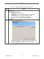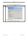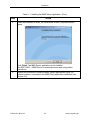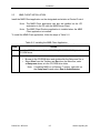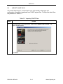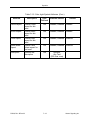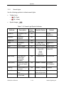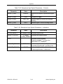
1
Maintenance
Management System
(MMS) Client/Server
(v4.1.x)
for Alstom Vital Processor
Interlocking Systems
(VPI® II/iVPI)
Copyright © 2012, 2013 Alstom Signaling Inc.
User Manual
P2528
Maintenance
Management System
(MMS) Client/Server
(v4.1.x)
for Alstom Vital Processor
Interlocking Systems
(VPI® II/iVPI)
Copyright © 2012, 2013 Alstom Signaling Inc.
User Manual
Alstom Signaling Inc.
P2528, Rev. B, December 2013, Printed in U.S.A.
LIST OF EFFECTIVE PAGES
P2528, Maintenance Management System (MMS), Client/Server version (4.1.x) for
Alstom Vital Processor Interlocking Systems (VPI® II/iVPI) User Manual
ORIGINAL ISSUE DATE:
August 2012
CURRENT REVISION AND DATE:
Rev B, December 2013
PAGE
CHANGE OR REVISION LEVEL
Cover
December 2013
Title page
December 2013
Preface
December 2013
i through viii
December 2013
1–1 through 1–12
December 2013
2–1 through 2–14
December 2013
3–1 through 3–8
December 2013
4–1 through 4–20
December 2013
5–1 through 5–24
December 2013
6–1 through 6–28
December 2013
7–1 through 7–32
December 2013
8–1 through 8-2
December 2013
9–1 through 9-2
December 2013
P2528, Rev. B, Dec/13
Alstom Signaling Inc.
THIS PAGE INTENTIONALLY LEFT BLANK.
P2528, Rev. B, Dec/13
Alstom Signaling Inc.
PREFACE
NOTICE OF CONFIDENTIAL INFORMATION
Information contained herein is confidential and is the
property of Alstom Signaling Incorporated. Where furnished
with a proposal, the recipient shall use it solely to evaluate
the proposal. Where furnished to customer, it shall be used
solely for the purposes of inspection, installation or
maintenance. Where furnished to a supplier, it shall be used
solely in the performance of the contract. The information
shall not be used or disclosed by the recipient for any other
purposes whatsoever.
VPI®, WEE-Z®, and Microchron® are registered trademarks of Alstom Signaling Inc.
GM4000A™, iVPI™, microWIU™, and VCS™ are trademarks of Alstom Signaling Inc.
All other trademarks referenced herein are trademarks of their respective owners.
FOR QUESTIONS AND INQUIRIES, CONTACT CUSTOMER SERVICE AT
1–800–717–4477
OR
WWW.ALSTOMSIGNALINGSOLUTIONS.COM
ALSTOM SIGNALING INC.
1025 JOHN STREET
WEST HENRIETTA, NY 14586
REVISION LOG
Revision
0(A)
B
Date
Description
Author
Checker
Approver
August
2012
Original issue
JF
KS
KS
December
2013
Updates to update and
clarify screenshots.
SG
KS
MS
P2528, Rev. B, Dec/13
Alstom Signaling Inc.
THIS PAGE INTENTIONALLY LEFT BLANK.
P2528, Rev. B, Dec/13
Alstom Signaling Inc.
ABOUT THE MANUAL
This manual is intended to provide the necessary information to maintain and ensure
proper operation of the Client/Server version (4.1.x) of Maintenance Management
System (MMS) for Alstom Vital Processor Interlocking Systems (VPI® II/iVPI).
The information in this manual is arranged into sections. The title and a brief description
of each section follow:
Section 1 – GENERAL DESCRIPTION: This section provides general information on
the components of MMS.
Section 2 – INSTALLATION: This section describes how to install the MMS Server and
MMS Client applications.
Section 3 – MMS SERVER: This section explains how to start the MMS Server
application, shut it down, and configure it as needed.
Section 4 – MMS CLIENT MAIN: This section explains how to start the MMS Client
Main application, shut it down, and configure it as needed.
Section 5 – MMS EDITOR: This section explains how to use the MMS Editor
application.
Section 6 – MMS CLIENT RUNTIME: This section explains how to use the MMS Client
Runtime application.
Section 7 – SYMBOLS: This section describes the layout symbols used in the MMS
programs.
Section 8 – VPI PORT CONFIGURATION: This section explains how to configure VPI
ports to acquire data for MMS.
Section 9 – MMS COMMUNICATION: This section contains block diagrams describing
MMS communication.
P2528, Rev. B, Dec/13
Alstom Signaling Inc.
THIS PAGE INTENTIONALLY LEFT BLANK.
P2528, Rev. B, Dec/13
Alstom Signaling Inc.
MANUAL SPECIAL NOTATIONS
In the Alstom manuals, three methods are used to convey special informational
notations. These notations are warnings, cautions, and notes. Both warnings and
cautions are readily noticeable by boldface type and a box around the entire
informational statement.
Warning
A warning is the most important notation to heed. A warning is used to tell the reader
that special attention needs to be paid to the message because if the instructions or
advice is not followed when working on the equipment then the result could be either
serious harm or death. The sudden, unexpected operation of a switch machine, for
example, or the technician contacting the third rail could lead to personal injury or death.
An example of a typical warning notice follows:
WARNING
Disconnect motor energy whenever working on switch layout or switch
machine. Unexpected operation of machine could cause injury from open
gears, electrical shock, or moving switch points.
Caution
A caution statement is used when failure to follow the recommended procedure could
result in loss or alteration of data. A typical caution found in a manual is as follows:
CAUTION
Changing session date and time to earlier values may affect the ability of the
History Window to store data correctly.
Note
A note is normally used to provide minor additional information to the reader to explain
the reason for a given step in a test procedure or to just provide a background detail. An
example of the use of a note follows:
Note: This step should be done first to validate the correct information
is used.
P2528, Rev. B, Dec/13
Alstom Signaling Inc.
THIS PAGE INTENTIONALLY LEFT BLANK.
P2528, Rev. B, Dec/13
Alstom Signaling Inc.
TABLE OF CONTENTS
Topic
Page
SECTION 1 – GENERAL DESCRIPTION ................................................................... 1–1
1.1
SCOPE OF MANUAL ................................................................................ 1–1
1.2
OVERVIEW ............................................................................................... 1–1
1.3
MAINTENANCE MANAGEMENT SYSTEM .............................................. 1–1
1.4
REQUIREMENTS/FEATURES .................................................................. 1–2
1.5
PRODUCT PART NUMBERS .................................................................... 1–3
1.6
DOCUMENT CONVENTIONS ................................................................... 1–3
1.7
GLOSSARY OF TERMS............................................................................ 1–4
1.8
CONTROL SYSTEM.................................................................................. 1–7
1.8.1
VPI® II/iVPI Application ................................................................... 1–7
1.8.2
VPI Communication Ports ............................................................... 1–8
1.9
MMS EDITOR ............................................................................................ 1–9
1.9.1
MMS Projects .................................................................................. 1–9
1.10
MMS SERVER......................................................................................... 1–11
1.11
MMS CLIENT........................................................................................... 1–12
1.11.1
MMS Client Main ........................................................................... 1–12
1.11.2
MMS Client Runtime ..................................................................... 1–12
SECTION 2 – INSTALLATION.................................................................................... 2–1
2.1
OVERVIEW ............................................................................................... 2–1
2.2
MMS SERVER INSTALLATION ................................................................ 2–2
2.3
MMS CLIENT INSTALLATION .................................................................. 2–7
SECTION 3 – MMS SERVER ...................................................................................... 3–1
3.1
OVERVIEW ............................................................................................... 3–1
3.2
CONNECT TO A VPI SYSTEM ................................................................. 3–1
3.3
MMS SERVER START-UP ........................................................................ 3–3
3.4
MMS SERVER OPTIONS.......................................................................... 3–4
3.5
MMS SERVER HELP ................................................................................ 3–6
3.6
MMM SERVER SHUTDOWN .................................................................... 3–7
SECTION 4 – MMS CLIENT MAIN ............................................................................. 4–1
4.1
OVERVIEW ............................................................................................... 4–1
4.2
MMS CLIENT START-UP .......................................................................... 4–1
4.3
MMM CLIENT USER INTERFACE ............................................................ 4–3
4.3.1
Overview ......................................................................................... 4–3
P2528, Rev. B, Dec/13
i
Alstom Signaling Inc.
TABLE OF CONTENTS
Topic
Page
4.3.2
Locations Panel............................................................................... 4–4
4.3.3
Tools Menu ..................................................................................... 4–5
4.3.3.1
Security ................................................................................... 4–5
4.3.3.2
Server Configuration ............................................................... 4–6
4.3.3.3
Refresh Server Connections ................................................... 4–8
4.3.3.4
Options.................................................................................... 4–9
4.3.3.5
Task Scheduler ..................................................................... 4–12
4.3.4
MMS Client Help ........................................................................... 4–17
4.4
SECURITY LEVELS ................................................................................ 4–18
4.5
MMS CLIENT SHUTDOWN..................................................................... 4–19
SECTION 5 – MMS EDITOR ....................................................................................... 5–1
5.1
OVERVIEW ............................................................................................... 5–1
5.2
MMS EDITOR USER INTERFACE ............................................................ 5–1
5.3
CONFIGURE MMS EDITOR OPTIONS .................................................... 5–3
5.4
CREATE A NEW MMS PROJECT ............................................................ 5–6
5.5
BUILD THE LOCATION MODEL ............................................................. 5–10
5.6
IMPORT CAAPE DATA ........................................................................... 5–13
5.7
LINK VPI VARIABLES TO SYMBOL PARAMETERS .............................. 5–18
5.8
ADD MMS SPECIFIC DATA .................................................................... 5–20
5.9
CREATE A SUMMARY REPORT ............................................................ 5–23
5.10
PRINT A LAYOUT DRAWING ................................................................. 5–24
SECTION 6 – MMS CLIENT RUNTIME ...................................................................... 6–1
6.1
OVERVIEW ............................................................................................... 6–1
6.2
ACCESSING MMS CLIENT RUNTIME ..................................................... 6–2
6.3
MMS CLIENT RUNTIME USER INTERFACE ........................................... 6–3
6.3.1
Main Screen .................................................................................... 6–3
6.3.1.1
Project Watch Window ............................................................ 6–5
6.3.1.2
Settings (Preferences) ............................................................ 6–7
6.3.1.3
Help....................................................................................... 6–10
6.3.1.4
Control Systems .................................................................... 6–11
6.3.1.5
Status Bar ............................................................................. 6–11
6.3.1.6
Tools ..................................................................................... 6–12
6.3.2
Maintenance Diagnostics .............................................................. 6–13
6.3.3
Application Explorer ...................................................................... 6–15
6.3.4
Log Manager ................................................................................. 6–23
6.3.5
Configuration Manager.................................................................. 6–25
P2528, Rev. B, Dec/13
ii
Alstom Signaling Inc.
TABLE OF CONTENTS
Topic
Page
6.3.6
Network Statistics Screen ............................................................. 6–27
SECTION 7 – SYMBOLS ............................................................................................ 7–1
7.1
OVERVIEW ............................................................................................... 7–1
7.2
TRACK SYMBOLS .................................................................................... 7–1
7.2.1
Overlay Track .................................................................................. 7–1
7.2.2
Non-Coded Track ............................................................................ 7–3
7.2.3
Coded Track ................................................................................... 7–6
7.3
SWITCH SYMBOLS .................................................................................. 7–9
7.4
LIGHT SYMBOLS .................................................................................... 7–12
7.4.1
Color Lights ................................................................................... 7–12
7.4.2
Position Lights ............................................................................... 7–15
7.4.3
Search Lights ................................................................................ 7–18
7.4.4
Semaphore Lights ......................................................................... 7–21
7.5
MISCELLANEOUS SYMBOLS ................................................................ 7–23
7.5.1
Alternate Traffic ............................................................................. 7–23
7.5.2
Grade Crossing ............................................................................. 7–24
7.5.3
Remote/Local Control ................................................................... 7–26
7.5.4
Timer ............................................................................................. 7–27
7.5.5
Generic ......................................................................................... 7–28
7.5.6
Direction Indicator ......................................................................... 7–30
7.5.7
Alarm............................................................................................. 7–31
7.5.8
Text Box ........................................................................................ 7–32
SECTION 8 – VPI PORT CONFIGURATION ............................................................... 8-1
8.1
VITAL BOARD NETWORK PORTS ........................................................... 8-1
8.2
NON-VITAL BOARD NETWORK PORTS .................................................. 8-1
8.3
COMPILER REPORT OPTIONS ................................................................ 8-2
SECTION 9 – MMS COMMUNICATION ...................................................................... 9-1
9.1
DATA LOG RETRIEVAL PROCESSING .................................................... 9-1
P2528, Rev. B, Dec/13
iii
Alstom Signaling Inc.
LIST OF FIGURES
Figure No.
Title
Figure 2–1.
MMS Server/Client Installation Overview ........................................ 2–1
Figure 3–1.
Figure 3–2.
CPU II and CSEX4 Diagnostics ...................................................... 3–2
VSP and NVSP Diagnostics ............................................................ 3–2
Figure 4–1.
Figure 4–2.
Figure 4–3.
Figure 4–4.
Figure 4–5.
MMS Client User Interface .............................................................. 4–3
MMS Client, Locations Panel .......................................................... 4–4
MMS Client, Tools Menu ................................................................. 4–5
Cached Login Window .................................................................... 4–5
Server Connection Refresh in Progress .......................................... 4–8
Figure 5–1.
MMS Editor User Interface .............................................................. 5–1
Figure 6–1.
Figure 6–2.
Figure 6–3.
Figure 6–4.
Figure 6–5.
Figure 6–6.
Figure 6–7.
Figure 6–8.
Figure 6–9.
Figure 6–10.
Figure 6–11.
Figure 6–12.
Figure 6–13.
Figure 6–14.
Figure 6–15.
Figure 6–16.
Figure 6–17.
MMS Main Screen ........................................................................... 6–3
Main Screen Project Watch Window Button .................................... 6–5
Main Screen Project Watch Window ............................................... 6–5
Main Screen Settings (Preferences) Button .................................... 6–7
Main Screen Settings – General Tab .............................................. 6–7
Main Screen Settings – Colors / Generic Tab ................................. 6–8
Main Screen Settings – Colors / General Tab ................................. 6–8
Main Screen Help Menu Button .................................................... 6–10
Main Screen Control Systems ....................................................... 6–11
Main Screen Status Bar ................................................................ 6–11
Main Screen Tools ........................................................................ 6–12
Maintenance Diagnostics Screen .................................................. 6–13
Application Explorer Screen .......................................................... 6–15
Watch Window Options Menu ....................................................... 6–18
Log Manager Screen ..................................................................... 6–23
Configuration Manager Screen ..................................................... 6–25
Communication Explorer – Network Statistics Screen .................. 6–27
Figure 9–1.
Data Log Retrieval Processing ......................................................... 9-2
P2528, Rev. B, Dec/13
Page
iv
Alstom Signaling Inc.
LIST OF TABLES
Table No.
Title
Table 1–1.
Table 1–2.
Table 1–3.
Table 1-4.
Table 1–5.
Table 1–6.
Table 1–7.
Minimum PC Requirements ............................................................ 1–2
Control System Component Requirements ..................................... 1–2
Commercialized Product Part Numbers .......................................... 1–3
Document Conventions ................................................................... 1–3
Glossary of Terms ........................................................................... 1–4
MMS Projects Features Available with Specific VPI® II/iVPI
and/or CAAPE Software ................................................................ 1–10
MMS Client Runtime Pages .......................................................... 1–12
Table 2–1.
Table 2–2.
Installing the MMS Server Application ............................................. 2–2
Installing the MMS Client Application .............................................. 2–7
Table 3–1.
Table 3–2.
Table 3–3.
Table 3–4.
Table 3–5.
Table 3–6.
VPI II/iVPI Connection Ports ........................................................... 3–1
Starting the MMS Server Application .............................................. 3–3
Accessing the MMS Server Settings Tabs ...................................... 3–4
MMS Server Settings Tab Descriptions........................................... 3–5
Accessing the MMS Server Help ..................................................... 3–6
Shutting Down the MMS Server ...................................................... 3–7
Table 4–1.
Table 4–2.
Table 4–3.
Table 4–4.
Table 4–5.
Table 4–6.
Table 4–7.
Table 4–8.
Table 4–9.
Starting the MMS Client Application ................................................ 4–2
MMS Client User Interface Details .................................................. 4–3
Location Panel, Default Status Color Indications ............................ 4–4
Configuring MMS Servers ............................................................... 4–6
Setting MMS Client Color/Sound Options ....................................... 4–9
Using the Task Scheduler ............................................................. 4–12
Accessing the MMS Client Help .................................................... 4–17
Security Levels and Functions ...................................................... 4–18
Shutting Down the MMS Client ..................................................... 4–19
Table 5–1.
Table 5–2.
Table 5–3.
Table 5–4.
Table 5–5.
Table 5–6.
Table 5–7.
Table 5–8.
MMS Editor User Interface Descriptions ......................................... 5–2
Modifying MMS Editor User Preferences ........................................ 5–3
General Tab Preferences ................................................................ 5–4
Colors Tab Sub-tabs ....................................................................... 5–5
Creating a New MMS Project .......................................................... 5–6
Building the Location Model .......................................................... 5–10
Importing CAAPE Data.................................................................. 5–13
CAAPE Project Data Imported by the MMS Editor When
.CPB is Used ................................................................................. 5–17
Linking VPI Variables to Symbol Parameters ................................ 5–18
Adding MMS Data to the Build File ............................................... 5–20
Creating a Summary Report.......................................................... 5–23
Table 5–9.
Table 5–10.
Table 5–11.
P2528, Rev. B, Dec/13
Page
v
Alstom Signaling Inc.
LIST OF TABLES
Table No.
Title
Table 5–12.
Printing a Layout Drawing ............................................................. 5–24
Table 6–1.
Table 6–2.
Table 6–3.
Table 6–4.
Table 6–5.
Table 6–6.
Table 6–7.
Table 6–8.
Table 6–9.
Table 6–10.
Table 6–11.
Table 6–12.
Starting the MMS Client Runtime Application.................................. 6–2
MMS Main Screen Detail................................................................. 6–4
Main Screen Settings Tabs ............................................................. 6–9
Main Screen Help Menu ................................................................ 6–10
Main Screen Control System Status Indications ........................... 6–11
Main Screen Tools Descriptions.................................................... 6–12
Maintenance Diagnostics Screen Interface ................................... 6–14
Application Explorer Screen Interface ........................................... 6–16
Watch Window Options Menu Descriptions .................................. 6–19
Application Explorer Screen Settings Tabs ................................... 6–21
Log Manager Screen Interface ...................................................... 6–24
Configuration Manager Screen Interface....................................... 6–26
Table 7–1.
Table 7–2.
Table 7–3.
Table 7–4.
Table 7–5.
Table 7–6.
Table 7–7.
Table 7–8.
Table 7–9.
Table 7–10.
Table 7–11.
Table 7–12.
Table 7–13.
Table 7–14.
Table 7–15.
Table 7–16.
Table 7–17.
Table 7–18.
Table 7–19.
Table 7–20.
Table 7–21.
Table 7–22.
Table 7–23.
Table 7–24.
Table 7–25.
Overlay Track Symbol Attributes ..................................................... 7–1
Overlay Track Symbol Parameters – Indications ............................ 7–2
Non-Coded Track Symbol Attributes ............................................... 7–3
Non-Coded Track Symbol Parameters – Controls .......................... 7–4
Non-Coded Track Symbol Parameters – Indications ...................... 7–5
Coded Track Symbol Attributes....................................................... 7–6
Coded Track Symbol Parameters – Controls .................................. 7–8
Coded Track Symbol Parameters – Indications .............................. 7–8
Switch Symbol Attributes................................................................. 7–9
Switch Symbol Parameters – Controls .......................................... 7–11
Switch Symbol Parameters – Indications ...................................... 7–11
Color Light Symbol Attributes ........................................................ 7–12
Color Light Symbol Parameters – Controls ................................... 7–14
Color Light Symbol Parameters – Indications ............................... 7–14
Position Light Symbol Attributes.................................................... 7–15
Position Light Symbol Parameters – Controls ............................... 7–17
Position Light Symbol Parameters – Indications ........................... 7–17
Search Light Symbol Attributes ..................................................... 7–18
Search Light Symbol Parameters – Controls ................................ 7–20
Search Light Symbol Parameters – Indications ............................. 7–20
Semaphore Light Symbol Attributes .............................................. 7–21
Semaphore Light Symbol Parameters – Controls ......................... 7–22
Semaphore Light Symbol Parameters – Indications ..................... 7–22
Alternate Track Symbol Attributes ................................................. 7–23
Alternate Track Symbol Parameters – Indications ........................ 7–23
P2528, Rev. B, Dec/13
Page
vi
Alstom Signaling Inc.
LIST OF TABLES
Table No.
Title
Table 7–26.
Table 7–27.
Table 7–28.
Table 7–29.
Table 7–30.
Table 7–31.
Table 7–32.
Table 7–33.
Table 7–34.
Table 7–35.
Table 7–36.
Table 7–37.
Table 7–38.
Table 7–39.
Table 7–40.
Grade Crossing Symbol Attributes ................................................ 7–24
Grade Crossing Symbol Parameters – Indications........................ 7–25
Remote/Local Control Symbol Attributes....................................... 7–26
Remote/Local Control Symbol Parameters – Controls .................. 7–26
Remote/Local Control Symbol Parameters – Indications .............. 7–26
Timer Symbol Attributes ................................................................ 7–27
Timer Symbol Parameters – Indications........................................ 7–27
Generic Symbol Attributes............................................................. 7–28
Generic Symbol Parameters – Controls ........................................ 7–29
Generic Symbol Parameters – Indications .................................... 7–29
Direction Indicator Symbol Attributes ............................................ 7–30
Direction Indicator Symbol Parameters – Indications .................... 7–30
Alarm Symbol User-Defined Attributes .......................................... 7–31
Text Box Symbol Attributes ........................................................... 7–32
Text Box Symbol Parameters – Indications................................... 7–32
P2528, Rev. B, Dec/13
Page
vii
Alstom Signaling Inc.
THIS PAGE INTENTIONALLY LEFT BLANK.
P2528, Rev. B, Dec/13
viii
Alstom Signaling Inc.
General Description
SECTION 1 – GENERAL DESCRIPTION
1.1
SCOPE OF MANUAL
This manual provides the necessary information to properly operate and maintain the
Client/Server version (v4.1.x) of the Maintenance Management System (MMS) for
Alstom Vital Processor Interlocking Systems (VPI® II/iVPI).
1.2
OVERVIEW
This section briefly describes the components and physical characteristics of the
Maintenance Management System (MMS).
Note: The individual who installs MMS software must
administrator rights to the PC or laptop intended for use.
1.3
have
MAINTENANCE MANAGEMENT SYSTEM
Maintenance Management System (MMS) is a graphical Diagnostic and Maintenance
Application that uses a graphical Track Layout to dynamically record and display the
VPI diagnostic status along with the status of linked VPI variables.
Additional tools are available to manage diagnostics, view configuration information,
view event and data logs, schedule maintenance tasks and view recorded VPI
application variable data.
MMS consists of three applications:
•
MMS Editor is used to graphically create the MMS Project
•
MMS Server communicates with VPI systems and handles requests from MMS
Clients
•
MMS Client connects to MMS Servers, displays overall server status, and
graphically displays runtime information for individual servers
P2528, Rev. B Dec/13
1–1
Alstom Signaling Inc.
General Description
1.4
REQUIREMENTS/FEATURES
Table 1–1. Minimum PC Requirements
Component
Requirement
Operating System
Windows™ XP (SP2 & SP3), Windows™ Vista, Windows™ 7,
Windows™ Server 2008 (32-bit Operating Systems only)
RAM
2 GB
CPU
Intel II GHz Pentium or compatible
Hard Drive
100 GB available
Input Device
One of: Touch screen, Mouse, Trackball, Joystick
and a Keyboard
Display
SVGA (1024 x 768)
Ports
One network connection (two required for redundancy)
Other
CD-ROM drive
Table 1–2. Control System Component Requirements
Component
Requirement
VPI Application
Must be created using VPI II® /iVPI application built with CAAPE
version 12C or later
CSEX4 Board*
or
CSEX4 used in VPI® II Systems
NVSP Board
NVSP Board used in iVPI Systems
* Does not support CSE or CSEX1 boards.
P2528, Rev. B Dec/13
1–2
Alstom Signaling Inc.
General Description
1.5
PRODUCT PART NUMBERS
Table 1–3. Commercialized Product Part Numbers
Part Number
Commodity
Type
Description
51795-081-00
Software
XP,
Win7-32
VPI MMS Server/Editor,
Maintenance Management System
(Current Released Version is 4.1.x)
51795-082-00
Software
XP,
Win7-32
VPI MMS Client, Maintenance
Management System
(Current Released Version is 4.1.x)
1.6
DOCUMENT CONVENTIONS
The conventions in Table 1-4 are used in this manual.
Table 1-4. Document Conventions
Convention
bold
bold italic
italic
Description
In command lines, bold text represents information that should be
entered exactly as shown (keywords).
Bold italic text is used to indicate icons to activate or selections in the
menu tree.
Italic text is used to indicate a file name
[]
In command lines, square brackets indicate an option. To enter the
option, type only the information inside the brackets. Do not type the
brackets themselves.
|
When describing a menu selection, this character is used to separate
consecutive menu item choices. For example, File | Exit means to open
the File dropdown menu and select the Exit item.
P2528, Rev. B Dec/13
1–3
Alstom Signaling Inc.
General Description
1.7
GLOSSARY OF TERMS
Table 1–5. Glossary of Terms (Cont.)
Term
Definition
Application Explorer
Accesses the selected System's variable data obtained through
the diagnostic ports. Multiple logic, message, or I/O variables
can be viewed in near real time. Variables are displayed using
their assigned names and their current Boolean or integer
values. Application logic statements can be displayed including
the current values of the variables used to generate the
statements. Datalogged variable data can be displayed using
the playback feature.
CAAPE
Alstom’s Computer-Aided Application Programming
Environment software package converts Boolean expressions
into operating instructions for the VPI microprocessor to
generate interlocking logic configured to meet the needs of the
particular installation.
CIL
Central Instrument Location
Communication
Explorer
Provides access to serial ports through VT100. Display network
statistics for networked connections.
Configuration
Manager
Reports the expected and actual configuration items for each
Application of the selected System. Both hardware and firmware
items can be reported.
Control System
Hardware device connected to MMS computer. Currently only
VPI® II/iVPI systems are supported.
Control Variable
Data received by the VPI® II/iVPI system
CPU II
Central Processing Unit II board used in the VPI® II Vital
processor.
CPU/PD
Central Processing Unit/Polynomial Divider board used in the
VPI® Vital processor.
CSEX
A family of non-vital communications and I/O control boards,
including CSEX3 and CSEX4 used in VPI ® II systems.
Data Log
MMS events, System status, Diagnostics and VPI Data Logs
saved in the MMS database.
Drawing Area
The Layout area of the MMS Editor where the location model is
created. This is where symbols are placed and connected.
EULA
End-user license agreement
P2528, Rev. B Dec/13
1–4
Alstom Signaling Inc.
General Description
Table 1–5. Glossary of Terms (Cont.)
Term
Definition
HHT
Hand Held Terminal; a simple text-based diagnostic display
device.
Import Wizard
A set of dialogs that guide a user through the steps necessary
to place VPI information into the MMS Project database.
Indication Variable
Data received by the VPI® II/iVPI system
iVPI
Integrated Vital Processor Interlocking, an Alstom Vital wayside
control system.
LCS file
The compiler’s report file for a non-vital application (.lcs).
Log Manager
Handles the retrieval of VPI® II/iVPI data logs and the archival
and display of all log data.
LVC file
The compiler’s report file for a Vital processor application (.lvc).
MAC port
Maintenance ACcess Port; a port used to access diagnostic
data.
MMS
Maintenance Management System.
MMS Client
MMS Client consists of two applications. MMS Client Main
connects to MMS Servers,displays overall server status; and
allows the user to open MMS Client Runtime for an individual
server.
MMS Client Runtime
An application that graphically displays runtime information for
an individual server location.
MMS Editor
An application used to create MMS Project databases.
MMS Event Log
VPI® II/iVPI control and indication data is recorded as MMS
Event Log data.
MMS Server
An application that communicates with VPI systems and
handles requests from MMS Clients
Maintenance
Diagnostics
Graphical display of control system hardware status and
diagnostic data.
Non-Vital Processor
Board
A board responsible for the VPI® II/iVPI system non-vital
processing: CSEX4, NVSP.
NVSP
Non-Vital System Processor non-vital communications and I/O
control board used in iVPI systems.
NX
An eNtrance/eXit method of requesting a route through an
interlocking
Session
The period of time MMS is operational; a new session log is
created each time MMS is started.
P2528, Rev. B Dec/13
1–5
Alstom Signaling Inc.
General Description
Table 1–5. Glossary of Terms (Cont.)
Term
Definition
Status Bar
MMS information is displayed as an expandable text list; the last
50 items are displayed with their associated time stamps.
Symbol
A graphical object that represents a field device.
Task Scheduler
A basic calendar to do list allowing a user to control
maintenance tasks.
Track Layout
The graphical model of a location.
VDP
Vital Diagnostic Protocol; a means of routing Vital processor
diagnostic data through the diagnostic screens of a non-vital
processor board.
Vital Processor Board A board responsible for the VPI system non-vital processing:
CPU/PD, CPU II, VSP
VPI® II
Vital Processor Interlocking II, an Alstom Vital wayside control
system.
VPI Data Log
A collection of data retrieved from VPI® II CSEX Data Logger;
the VPI® II CSEX Data Logger must be enabled and the data
retrieved (see Section 6.3.4 Log Manager).
VSP
Vital System Processor board (used in iVPI systems).
P2528, Rev. B Dec/13
1–6
Alstom Signaling Inc.
General Description
1.8
CONTROL SYSTEM
MMS supports the following control systems:
•
VPI® II
•
iVPI
The control system is generally comprised of:
•
One Vital processor board that coordinates the Vital aspects of system operation
•
Up to four non-vital processor boards. A non-vital processor board coordinates nonvital communications and handles non-vital I/O. Non-vital only control systems
containing only non-vital processor boards are also feasible.
1.8.1
VPI® II/iVPI Application
Various VPI® II/iVPI boards contain user programming that is specifically developed for
the location where the system is installed. The programming for a particular board is
called an application. Each application includes logic statements that control the board's
behavior. Logic statements manipulate variables, which are memory locations
containing some discrete piece of information such as the status of an I/O port or a
message bit. The most common logic statement is the Boolean equation, which logically
combines the values of several variables to get a single True or False value and then
assigns that value to one or more results. Vital processor boards are capable of
processing only Boolean equations. Non-vital processor boards are also capable of
processing integer equations as well as more complex statements such as subroutines
and IF/ELSE.
The application programming for a board is produced by compiling graphical or text
based input files using software tools contained in the Computer-Aided Application
Programming Environment (CAAPE). The compile process of the CAAPE optionally
produces a report file which includes, among other things, a symbol table mapping
memory locations to variable names and a logic section listing the logic statements in
the application. Report files for Vital processor applications have an "LVC" extension;
report files for non-vital processor applications have an "LCS" extension.
P2528, Rev. B Dec/13
1–7
Alstom Signaling Inc.
General Description
1.8.2
VPI Communication Ports
Boards in the non-vital processor family produce diagnostic data that can be accessed
through the MAC serial port by a series of menu-driven screens which can be displayed
on a VT100 video terminal or an equivalent terminal emulator program.
Note: The Client/Server version (v4.1.x) of MMS currently does not
support MAC serial port connection to non-vital boards. Use
AlsDload, or an equivalent terminal emulator program, to make
such connections.
These boards can also produce real-time variable status data in a format compatible
with MMS but is not directly displayable on a video terminal. MMS can also use a
network diagnostic port for Data Log retrieval.
The Vital processor board provides diagnostic information in a text-based
query/response format that was originally meant for viewing with a hand held terminal.
Newer versions of VPI® II/iVPI system software also have a Vital Diagnostic Protocol
(VDP) option that can route diagnostic information from the Vital processor board
through either a serial port, or through dual-ported random access memory (RAM) to
the non-vital processor board and displayed through the non-vital processor board's
diagnostic screens.
P2528, Rev. B Dec/13
1–8
Alstom Signaling Inc.
General Description
1.9
MMS EDITOR
Use the MMS Editor to:
•
Graphically model a given location
•
Gather VPI application information
•
Link symbol parameters to VPI variables for each graphical element
•
Create an MMS Project database for use by MMS Client Runtime
•
Add alarms and sounds
•
Add security settings
•
Remove the color setting from generic symbols
The model of the plant is entered through the user-friendly Track Layout environment,
using symbols representing track circuits, switches, signals, timers, and other layout
hardware.
The Import Wizard function guides the user to easily enter VPI configuration data into
the MMS Project database. Individual Symbol parameters can be linked to VPI variables
by the “drag and drop” of VPI variable names into the parameter tables.
See SECTION 5 – MMS Editor for a detailed explanation of how to use the MMS Editor
to create an MMS Project.
1.9.1
MMS Projects
MMS Projects provides a variety of standard features:
•
Iconic representation of Control System status
•
Symbol parameter states graphically displayed and recorded
•
Board level diagnostics w/ solution guidelines
•
VPI® II/iVPI Vital and non-vital variable states displayed; can be recorded [up to 128
Vital variables per Application (see Table 1–6); up to 128 non-vital variables per
Application]
•
VPI® II/iVPI Application logic display
•
VPI® II/iVPI Data log retrieval; view Data logs and recorded data; Log reports
•
VPI® II/iVPI Configuration reports
•
To Do list for task scheduling
Additional features are available for newer VPI® II/iVPI and CAAPE software versions,
as summarized in Table 1–6.
P2528, Rev. B Dec/13
1–9
Alstom Signaling Inc.
General Description
Table 1–6. MMS Projects Features Available with Specific VPI® II/iVPI
and/or CAAPE Software
Feature
Requirement
View up to 128 Vital variable states
at one time in Application Explorer
VPI® II (CPU II) and iVPI (VSP) using Ethernet
and
CAAPE version 8 or later
and
MMS version 3.0 or later
View up to 128 non-vital variable
states at one time in Application
Explorer
iVPI (NVSP) using Ethernet
and
CAAPE version 8 or later
and
MMS version 3.0 or later
P2528, Rev. B Dec/13
1–10
Alstom Signaling Inc.
General Description
1.10
MMS SERVER
MMS Server is an application that communicates with VPI systems and handles
requests from MMS Clients.
MMS Servers reside on a network to allow communication to MMS Clients using
Windows Communication Foundation over TCP/IP.
MMS Server uses the data provided in an MMS Project database created with MMS
Editor. This database contains data describing the plant model and connected Control
Systems. MMS Server continuously displays the health of each connected control
system. If a problem is identified, diagnostic information is requested and logged.
Control Systems are connected through Ethernet ports to the MMS server computer,
allowing data to be stored and transferred to MMS clients. Controls and indications,
control system health, application equation and variable data, configuration information,
and data log information can be transferred.
The Control System information includes:
•
physical hardware layout and identification
•
type of system / application
•
variable data
•
equation logic data
•
network connection type and settings
P2528, Rev. B Dec/13
1–11
Alstom Signaling Inc.
General Description
1.11
MMS CLIENT
MMS Client consists of two applications, MMS Client Main and MMS Client Runtime.
MMS Client Main connects to MMS Servers, displays overall server status; and allows
the user to open MMS Client Runtime for an individual server.
1.11.1
MMS Client Main
MMS Client Main allows the user to:
•
View operational, communication & alarm status
•
Set up server configuration data
•
Set colors for status and assign sounds to alarms
•
Allows user to open MMS Client Runtime
1.11.2
MMS Client Runtime
MMS Client Runtime:
•
Uses a graphical point and click interface, eliminating the need to know command
sets for each protocol. Displayed graphical symbols change state based on the
linked control system variable data.
•
Continuously displays the health of each connected control system.
•
Displays information on designated pages (see Table 1–7)
Table 1–7. MMS Client Runtime Pages
Page
Description
Maintenance
Diagnostic
Displays recorded board level diagnostic information along with
troubleshooting and suggested solutions. Diagnostics can be
filtered, cleared and history viewed. See Section 6.3.2.
Application
Explorer
Displays variable states and equation logic for tracing possible
problems. Variable state data can be recorded to play later. Data
played later, variable state as well as VPI CSEX log data, is
displayed in a timing diagram format. See Section 6.3.3.
Log Manager
Retrieves VPI® II/iVPI CSEX data logs. These logs can be manually
or automatically retrieved as a timed task. Creates reports of MMS
events or data logs. See Section 6.3.4.
Configuration
Manager
Displays control system hardware and firmware configuration
information. See Section 6.3.5.
Communication
Explorer
Displays network statistics. See Section 6.3.6
P2528, Rev. B Dec/13
1–12
Alstom Signaling Inc.
Installation
SECTION 2 – INSTALLATION
2.1
OVERVIEW
This section describes how to install MMS Server/Editor and MMS Client on separate
workstations or on the same workstation.
A typical installation of the MMS Server and Client applications consists of:
•
Installing the MMS Server application in Central Control
•
Installing the MMS Client application on the VPI workstation in the Central
Instrument Location (CIL)
Both applications (MMS Server and Client) can be installed together on the VPI
workstation in the CIL. See Figure 2–1.
Figure 2–1. MMS Server/Client Installation Overview
P2528, Rev. B Dec/13
2–1
Alstom Signaling Inc.
Installation
2.2
MMS SERVER INSTALLATION
Install the MMS Server application at the location site where the VPI system is located.
Note: The MMS Editor application is installed when the MMS Server
application is installed.
To install the MMS Server application, follow the steps in Table 2–1.
Table 2–1. Installing the MMS Server Application (Cont.)
Step
Action
1
Insert the MMS Server installation CD-ROM (P/N 51795-082-00) into the
CD-ROM drive.
2
To start the installation process:
• Browse to the CD-ROM drive and double-click the Setup.exe file, or
• Select Start from the Taskbar and Run from the Menu bar; enter
x:\Setup.exe where x is the CD-ROM drive letter.
Note: If installing MMS on a Windows 7 system. Right-click
on the Setup.exe file and select Run as
Administrator.
3
The InstallShield Wizard Welcome screen opens.
Click Next.
P2528, Rev. B Dec/13
2–2
Alstom Signaling Inc.
Installation
Table 2–1. Installing the MMS Server Application (Cont.)
Step
4
Action
The License Agreement Screen opens.
Select I accept the terms in the license agreement.
Click Next.
5
The Customer Information screen opens.
P2528, Rev. B Dec/13
2–3
Alstom Signaling Inc.
Installation
Table 2–1. Installing the MMS Server Application (Cont.)
Step
Action
5
(Step 5 cont.)
Complete the fields as follows:
• User Name: Enter a user name.
• Organization: Enter the name of the organization using MMS.
• Serial Number: Enter the supplied MMS serial number.
• Select who can access the MMS Server application
(all users or only the user specified in User Name field).
Click Next.
6
The Destination Folder screen opens.
•
•
To change the default location where the MMS Server application is
installed, click Change and navigate to the desired location.
To install the MMS Server application in the default location, click Next.
P2528, Rev. B Dec/13
2–4
Alstom Signaling Inc.
Installation
Table 2–1. Installing the MMS Server Application (Cont.)
Step
7
Action
The Ready to Install screen opens.
Review the installation settings.
• To change any settings, click Back and make the necessary changes.
• To install the MMS Server application, click Install.
P2528, Rev. B Dec/13
2–5
Alstom Signaling Inc.
Installation
Table 2–1. Installing the MMS Server Application (Cont.)
Step
8
Action
When the installation is done, the InstallShield Wizard Completed screen
opens.
Click Finish. The MMS Server application is now installed.
See SECTION 3 – MMS Server for startup/shutdown and configuration
instructions.
9
Repeat this procedure to install the MMS Server application at other VPI
system locations, or proceed to the MMS Client application installation (see
Section 2.3).
P2528, Rev. B Dec/13
2–6
Alstom Signaling Inc.
Installation
2.3
MMS CLIENT INSTALLATION
Install the MMS Client application on the designated workstation at Central Control.
Note: The MMS Client application can also be installed on the VPI
workstation in the CIL with the MMS Server Client.
Note: The MMS Client Runtime application is installed when the MMS
Client application is installed.
To install the MMS Client application, follow the steps in Table 2–2.
Table 2–2. Installing the MMS Client Application (Cont.)
Step
Action
1
Insert the MMS Server installation CD-ROM (P/N 51795-082-01) into the
CD-ROM drive.
2
To start the installation process:
• Browse to the CD-ROM drive and double-click the Setup.exe file, or
• Select Start from the Taskbar and Run from the Menu bar; enter
x:\Setup.exe where x is the CD-ROM drive letter.
Note: If installing MMS on a Windows 7 system, right-click on
the Setup.exe file and select Run as Administrator.
P2528, Rev. B Dec/13
2–7
Alstom Signaling Inc.
Installation
Table 2–2. Installing the MMS Client Application (Cont.)
Step
3
Action
The InstallShield Wizard Welcome screen opens.
Click Next.
P2528, Rev. B Dec/13
2–8
Alstom Signaling Inc.
Installation
Table 2–2. Installing the MMS Client Application (Cont.)
Step
4
Action
The License Agreement Screen opens.
Select I accept the terms in the license agreement.
Click Next.
P2528, Rev. B Dec/13
2–9
Alstom Signaling Inc.
Installation
Table 2–2. Installing the MMS Client Application (Cont.)
Step
5
Action
The Customer Information screen opens.
Complete the fields as follows:
• User Name: Enter a user name.
• Organization: Enter the name of the organization using MMS.
• Serial Number: Enter the supplied MMS serial number.
• Select who can access the MMS Client application
(all users or only the user specified in User Name field).
Click Next.
P2528, Rev. B Dec/13
2–10
Alstom Signaling Inc.
Installation
Table 2–2. Installing the MMS Client Application (Cont.)
Step
6
Action
The Destination Folder screen opens.
•
•
To change the default location where the MMS Client application is
installed, click Change and navigate to the desired location.
To install the MMS Client application in the default location, click Next.
P2528, Rev. B Dec/13
2–11
Alstom Signaling Inc.
Installation
Table 2–2. Installing the MMS Client Application (Cont.)
Step
7
Action
The Ready to Install screen opens.
Review the installation settings.
• To change any settings, click Back and make the necessary changes.
• To install the MMS Client application, click Install.
P2528, Rev. B Dec/13
2–12
Alstom Signaling Inc.
Installation
Table 2–2. Installing the MMS Client Application (Cont.)
Step
8
Action
When the installation is done, the InstallShield Wizard Completed screen
opens.
Click Finish.
The MMS Client application is now installed.
See SECTION 4 – MMS Client Main for startup/shutdown and configuration
instructions.
If necessary, repeat this procedure to install the MMS Client application on a
VPI system workstation where the MMS Server application is installed.
P2528, Rev. B Dec/13
2–13
Alstom Signaling Inc.
Installation
THIS PAGE INTENTIONALLY LEFT BLANK.
P2528, Rev. B Dec/13
2–14
Alstom Signaling Inc.
MMS Server
SECTION 3 – MMS SERVER
3.1
OVERVIEW
This section explains how to:
•
Start the MMS Server application (Section 3.2)
•
Configure the MMS Server application (Section 3.4)
•
Shut the MMS Server application down (Section 3.6)
As described in Section 2.2, the MMS Server application is typically installed on the VPI
workstation located in the CIL.
3.2
CONNECT TO A VPI SYSTEM
MMS Server communicates with VPI processors via TCP/IP over Ethernet. IP
addresses for the MMS computer and VPI processors are configured in CAAPE, and
network ports are configured for connection to MMS in either the MMS Server Options
screen, or MMS Editor Additional MMS Data screen.
Table 3–1 provides a list of port types and their applicable connections. Examples of
various port connections are provided in Figure 3–1 and Figure 3–2.
Table 3–1. VPI II/iVPI Connection Ports
Port Type
Connection
CPU II
Preferred: CPU II network connections via Two 10/100-baseT
Ethernet network controllers.
CPU2 Main Processor diagnostic port.
CSEX4
Preferred: CSEX4 network connections via Two 10/100-baseT
Ethernet network controllers.
VSP
Preferred: VSP (iVPI) network connections via Two
10/100-baseT Ethernet network controllers.
VSP Main Processor diagnostic port.
NVSP
Preferred: NVSP (iVPI) connections via Two 10/100-baseT
Ethernet network controllers.
P2528, Rev. B Dec/13
3–1
Alstom Signaling Inc.
MMS Server
Ethernet 802.3 i/u
Switch
Switch
Local MMS PC
Remote MMS PC
TCP/IP
DT8-Slave
DT8-Slave
Panel
Tracker
Ethernet Devices 1 & 2
DPRAM
MAC-Diag
VPI SysBus
CSEX4
TCP/IP
MAC-Diag
Ethernet Devices
1&2
CPU II
MAC
RS232/USB
MAC
RS232/USB
RS232 –
Asyn 19.2K
RS232 –
Asyn 19.2K
Figure 3–1. CPU II and CSEX4 Diagnostics
Ethernet 802.3 i/u
Switch
Switch
Local MMS PC
Remote MMS PC
TCP/IP
MAC-Diag
Panel
Tracker
Ethernet Devices 1 & 2
MAC
RS232/USB
NVSP
DPRAM
VPI SysBus
TCP/IP
MAC-Diag
Ethernet Devices
1&2
VSP
MAC
RS232/USB
RS232 –
Asyn 19.2K
RS232 –
Asyn 19.2K
Figure 3–2. VSP and NVSP Diagnostics
P2528, Rev. B Dec/13
3–2
Alstom Signaling Inc.
MMS Server
3.3
MMS SERVER START-UP
To start the MMS Server application, follow the procedure in Table 3–2.
Note: For Windows 7, if security is set to any level above No
Security, right-click on the MMSService.exe file and set its
properties to Run as Administrator.
Note: Start the MMS Server Application first before starting the MMS
Client application. If the MMS Client application is started before
the MMS Server application, the two applications synchronize
once the MMS Server application is started.
Table 3–2. Starting the MMS Server Application
Step
Action
1
To start the MMS Server application, select Start | Programs | Alstom |
Maintenance Management System | Server |Server.
The MMS Server splash screen briefly appears.
2
Once the MMS Server application starts, an icon appears in the workstation’s
system icon tray.
Right-click on the icon to access the following options:
• Options (see Section 3.4)
• Help (see Section 3.5)
• Shutdown (see Section 3.6)
P2528, Rev. B Dec/13
3–3
Alstom Signaling Inc.
MMS Server
3.4
MMS SERVER OPTIONS
The MMS Server application provides several settings tabs to configure server
operation. To access the settings tabs, follow the procedure in Table 3–3.
Table 3–3. Accessing the MMS Server Settings Tabs
Step
Action
1
On the VPI system workstation with the MMS Server application installed, rightclick on the MMS Server icon in the system tray. From the pop-up menu, select
Options.
2
The Settings window opens.
Select the tab (or tabs) and make the necessary configurations. See Table 3–4
for descriptions of the MMS Server Settings tabs.
3
When all configuration settings are made, click OK to save the settings and
close the Settings window.
P2528, Rev. B Dec/13
3–4
Alstom Signaling Inc.
MMS Server
Table 3–4. MMS Server Settings Tab Descriptions
Tab
Description
Projects
Use this tab to choose a project on startup or select a project to load
at MMS Server startup.
Endpoints
Use this tab to set endpoint connection IP addresses.
Endpoints are the server IP addresses that are used to
communicate with the remote client(s). For the Main IP and Backup
IP, select <none>, or enter a unique IP address in each field.
Ports
Use this tab to configure the VPI/MMS serial communication ports.
The initial screen shows the active ports with buttons to Add,
Remove, and Show Properties.
• Add: Click to add network and serial ports
•
Remove: Click to remove selected active ports
•
Properties: Click to modify a selected active port
Clock Sync
Use this tab to synchronize all VPI system clocks to the MMS clock.
For this function to work, do not use the VPI password.
Record
Use this tab to set recording properties.
Enable or disable the recording of panel events, status bar text, and
data log retrieval text in the MMS log. System status and diagnostics
are always recorded.
Log Retrieval
Archive
Use this tab to configure automatic data log retrieval.
• Automatic Log retrieval enabled: Click this box to enable
automatic retrieval of the data log.
•
Interval: Set the retrieval interval (days/hours).
•
Next scheduled retrieval: Schedule when the next retrieval will
occur (date/time).
Use this tab to configure automatic archiving.
• Automatic Archive enabled: Click this box to enable automatic
archiving.
•
P2528, Rev. B Dec/13
Archive schedule: Set the archiving interval (month/days) and
schedule when the next archiving will occur (day/month/year).
3–5
Alstom Signaling Inc.
MMS Server
3.5
MMS SERVER HELP
To access the embedded help file and About screen provided in the MMS Server
application, follow the procedure in Table 3–5.
Table 3–5. Accessing the MMS Server Help
Step
Action
1
On the VPI system workstation with the MMS Server application installed, rightclick on the MMS Server icon in the system tray. From the pop-up menu, select
Help.
There are two options under Help. Select the desired option.
• Help topics: Select this option to open the MMS Server help file. The
help file contains information on how to configure and operate the MMS
Server application.
• About: Select this option to open the MMS Server About screen. This
screen shows the server release version, license code, and end-user
license agreement (EULA).
P2528, Rev. B Dec/13
3–6
Alstom Signaling Inc.
MMS Server
3.6
MMM SERVER SHUTDOWN
To shutdown (exit) the MMS Server application, follow the procedure in Table 3–6.
Table 3–6. Shutting Down the MMS Server
Step
Action
1
On the VPI system workstation with the MMS Server application installed,
right-click on the MMS Server icon in the system tray. From the pop-up menu,
select Shutdown.
The MMS Server application closes. The system tray icon disappears.
P2528, Rev. B Dec/13
3–7
Alstom Signaling Inc.
MMS Server
THIS PAGE INTENTIONALLY LEFT BLANK.
P2528, Rev. B Dec/13
3–8
Alstom Signaling Inc.
MMS Client Main
SECTION 4 – MMS CLIENT MAIN
4.1
OVERVIEW
This section explains how to:
•
Start the MMS Client Main application (Section 4.2)
•
Use the MMS Client Main application (Section 4.3)
•
Manage the security level settings (Section 4.4)
•
Shut the MMS Client Main application down (Section 4.5)
As described in Section 2.3, the MMS Client application is typically installed on a
designated workstation located in Central Control. The MMS Client application can also
be installed on the VPI system workstation located in the CIL.
4.2
MMS CLIENT START-UP
To start the MMS Client application, follow the procedure in Table 4–1.
Note: For Windows 7, if security is set to any level above No
Security, right-click on the MMS_Client_Main.exe file and set
its properties to Run as Administrator.
Note: Start the MMS Server Application first before starting the MMS
Client application. If the MMS Client application is started before
the MMS Server application, the two applications synchronize
once the MMS Server application is started.
P2528, Rev. B Dec/13
4–1
Alstom Signaling Inc.
MMS Client Main
Table 4–1. Starting the MMS Client Application
Step
Action
1
To start the MMS Client application, select Start | Programs | Alstom |
Maintenance Management System | Client | Client.
The MMS Client splash screen briefly appears.
2
The MMS Client Login window opens.
Click OK. The MMS Client application opens.
Note: Login is not necessary if only Level 1 (default) security is needed
(see Section 4.4). If security access above Level 1 security is
needed, enter a valid user name and password. MMS allows for
three login attempts. After three failed attempts, the user is
logged in with Level 1 security access.
Note: The login is cached and is sent to each location server when the
location is opened. Login is only needed once unless a higher
security level is needed.
P2528, Rev. B Dec/13
4–2
Alstom Signaling Inc.
MMS Client Main
4.3
MMM CLIENT USER INTERFACE
4.3.1
Overview
The MMS Client application provides access to each installed MMS Server application
on the network. The user interface consists of the following:
From the MMS Client application, the MMS user can:
•
Configure servers and refresh server connections
•
Assign color associations to the server statuses displayed (see Section 4.3.3.4)
•
Assign a sound file to play when an alarm occurs (see Section 4.3.3.4)
•
Set tasks in the Task Scheduler
•
Open the MMS Client Runtime application for a specific MMS Server location
See Figure 4–1 and Table 4–2 for more information.
Figure 4–1. MMS Client User Interface
Table 4–2. MMS Client User Interface Details
Callout
Description
1
File Menu. Contains Exit function. See Section 4.5 for more information.
2
Tools Menu. Contains configuration options. See Section 4.3.2 for more
information.
3
Help Menu. Contains the MMS online help file. See Section 4.3.4 for more
information.
4
Locations Panel. Displays status for all MMS servers (locations) on the
network. See Section 4.3.2 for more information.
P2528, Rev. B Dec/13
4–3
Alstom Signaling Inc.
MMS Client Main
4.3.2
Locations Panel
The Locations Panel:
•
Displays status for all MMS Servers (locations) on the network
•
Launches the MMS Client Runtime application for a selected MMS Server
(location); see Section 6.3
Figure 4–2. MMS Client, Locations Panel
The Locations Panel displays the following information for each MMS Server:
•
Server Name (Server column)
•
Server Address and connection status via color indication
•
Status (Operational, Communication, and Alarm)
The Locations Panel uses text displays (Unknown, Nominal, Warning, and Error) and
color indications to provide server status. See Table 4–3 for default color indications.
Table 4–3. Location Panel, Default Status Color Indications
Status Indication
Default Color
Unknown
Dodger Blue
Error
Red
Nominal
Green
Warning
Yellow
Connected
White
Disconnected
Red
None
Green
Acknowledged
Yellow
Active
Red
To change the default color indications, see Section 4.3.3.4.
P2528, Rev. B Dec/13
4–4
Alstom Signaling Inc.
MMS Client Main
4.3.3
Tools Menu
Use the Tools Menu to:
•
Log in/out for security level access to MMS functions
•
Add, remove, and configure MMS servers installed on the network
•
Refresh server connections
•
Assign color and sound associations for server status displays
•
Access the Task Scheduler
Figure 4–3. MMS Client, Tools Menu
4.3.3.1
Security
Select this option to log in for a higher access level than Security Level 1 (default) or the
level logged in as when the MMS Client application was launched.
Figure 4–4. Cached Login Window
For more information on security levels, see Section 4.4.
P2528, Rev. B Dec/13
4–5
Alstom Signaling Inc.
MMS Client Main
4.3.3.2
Server Configuration
Select this option to add a new server, change the properties for an existing server, or
remove an existing server. Follow the procedure in Table 4–4.
Table 4–4. Configuring MMS Servers (Cont.)
Step
Action
1
From the MMS Client user interface, select Tools | Server Configuration.
The Servers window opens.
2
To add a new server, click the Add button. The Server Properties window
opens.
P2528, Rev. B Dec/13
4–6
Alstom Signaling Inc.
MMS Client Main
Table 4–4. Configuring MMS Servers (Cont.)
Step
Action
2
(Step 2 cont.)
Configure the new server as follows:
• Name: Enter a name for the new server.
• Local/Remote: Select whether the server is a local server (installed with
the MMS Client application) or remote. If MMS Server is on the same
computer as MMS Client, select Local.
• IP Address: If the server is a remote server, enter a unique IP address.
• Port: The port number is fixed at 8000.
• Connect: Check this box to enable the server to automatically connect
to the MMS Client application when the MMS Client application is
started.
When all settings are made, click OK. The Servers window returns.
3
To configure an existing server, select the desired server from the Servers
window. Use the Up/Down arrows to scroll through the list of servers.
Click the Properties button. The Server Properties window opens. Change the
properties as needed. See Step 2 above for more information.
4
To remove a server, select the desired server from the Servers window. Use
the Up/Down arrows to scroll through the list of servers.
Click the Remove button. The server is removed from the list in the Servers
window.
Note: The server that was removed continues to show in the
Location Panel on the MMS Client until the server
connections are refreshed. See Section 4.3.3.3.
P2528, Rev. B Dec/13
4–7
Alstom Signaling Inc.
MMS Client Main
4.3.3.3
Refresh Server Connections
Select this option to refresh connections to all MMS Servers on the network. If any
configuration changes were made (for example, a server was added or removed), the
change appears in the MMS Client Location Panel after server connections are
refreshed.
As server connections are refreshed, the Location Panel goes blank (see Figure 4–5),
then returns with updated connection status.
Figure 4–5. Server Connection Refresh in Progress
P2528, Rev. B Dec/13
4–8
Alstom Signaling Inc.
MMS Client Main
4.3.3.4
Options
Select this option to configure the status indication-to-color association used in the MMS
Client Location Panel. Use this option to also assign a sound file to alarms. Follow the
procedure in Table 4–5.
Table 4–5. Setting MMS Client Color/Sound Options (Cont.)
Step
1
Action
From the MMS Client user interface, select Tools | Options.
The Options window opens with the Colors tab in front.
P2528, Rev. B Dec/13
4–9
Alstom Signaling Inc.
MMS Client Main
Table 4–5. Setting MMS Client Color/Sound Options (Cont.)
Step
2
Action
To change the default color association for the server status indications, click
on the color menu to the right of the desired status indication. Select the
desired color.
Repeat this step to change the color association for other status indications.
P2528, Rev. B Dec/13
4–10
Alstom Signaling Inc.
MMS Client Main
Table 4–5. Setting MMS Client Color/Sound Options (Cont.)
Step
3
Action
To assign a sound file to alarms, click the Sounds tab.
Click the Browse button and select a sound file from the default location
(shown above), or navigate to another file location and select the desired
sound file.
4
Click OK to save color and sound associations made and close the Options
window. The MMS Client returns.
P2528, Rev. B Dec/13
4–11
Alstom Signaling Inc.
MMS Client Main
4.3.3.5
Task Scheduler
Use the Task Scheduler to add and manage tasks (for example, system maintenance
tasks). Follow the procedure in Table 4–6.
Table 4–6. Using the Task Scheduler (Cont.)
Step
1
Action
From the MMS Client user interface, select Tools | Task Scheduler.
The Task Scheduler window opens.
P2528, Rev. B Dec/13
4–12
Alstom Signaling Inc.
MMS Client Main
Table 4–6. Using the Task Scheduler (Cont.)
Step
2
Action
To add a new task, click the New Task button (
The New Task window opens.
).
Complete the fields as follows:
• Task: Enter a descriptive name for the new task.
• Priority: Select a priority for the new task (Low, Normal, Urgent).
• Entry: Select the date and time that the new task was entered.
• Due: Select the date and time that the new task must be completed by.
Note: The Task Scheduler assigns the ID number when the new task is
added (by clicking OK on the New Task window).
Click OK when done. The New Task window closes and the Task Scheduler
returns.
P2528, Rev. B Dec/13
4–13
Alstom Signaling Inc.
MMS Client Main
Table 4–6. Using the Task Scheduler (Cont.)
Step
3
Action
To view a scheduled task, in the left-hand column in the Calendar pane, click
on a date in bold. Any tasks scheduled to be completed appear in the Task
pane.
Note: A bold date = task due date; a red-circled date = task assigned
date.
The Task pane consists of the information entered in the New Task window
(see previous Step).
Note: The ID cell is a read-only cell. The Task Scheduler assigns the ID
number to each new task.
A task can be edited, copied, marked as completed, deleted, or printed. See
the following steps for more information.
P2528, Rev. B Dec/13
4–14
Alstom Signaling Inc.
MMS Client Main
Table 4–6. Using the Task Scheduler (Cont.)
Step
4
Action
To change an existing task, select a task in the Task pane and click the
Edit Task button (
). The Edit Task window opens.
Edit the fields as needed. The ID field is read-only. See Step 2 for field
descriptions.
Click OK to save changes and close the Edit Task window. The Task
Scheduler returns.
5
To copy an existing task, select the task to be copied and click the Copy Task
button (
). The new task appears in the Task pane below the task from
which it was copied. The Task Scheduler assigns a new ID to the copy.
P2528, Rev. B Dec/13
4–15
Alstom Signaling Inc.
MMS Client Main
Table 4–6. Using the Task Scheduler (Cont.)
Step
6
Action
To mark a task as completed, select the task and click the Complete Task
button (
). The Completed window opens.
Select the date and time and click OK. The selected date/time appears in the
Completed Date column in the Task pane.
7
To delete a task, select the task and click the Remove Task button (
).
Note: There is no undo with the Remove function.
8
To print a task report, select the task and click the Print Task button (
send a task report to the default printer.
P2528, Rev. B Dec/13
4–16
) to
Alstom Signaling Inc.
MMS Client Main
4.3.4
MMS Client Help
To access the embedded help file and About screen provided in the MMS Client
application, follow the procedure in Table 4–7.
Table 4–7. Accessing the MMS Client Help
Step
1
Action
From the MMS Client User Interface, select the Help menu.
There are two options under Help. Select the desired option.
• Help Topics: Select this option to open the MMS Cleint help file. The
help file contains information on how to configure and operate the MMS
Client application.
• About: Select this option to open the MMS Client About screen. This
screen shows the client release version and license code.
P2528, Rev. B Dec/13
4–17
Alstom Signaling Inc.
MMS Client Main
4.4
SECURITY LEVELS
MMS provides three levels of security service upon login.
If login is done when the MMS Client application starts up, the user name and password
is cached in MMS and sent to each MMS Server application (location) when the location
is accessed from the MMS Client Location Panel. See Section 4.2 for more information.
Security login can also be done after the MMS Client application is started. See Section
4.3.3.1 for more information. See Table 4–8 for functions available at each security
level.
Table 4–8. Security Levels and Functions
Security Level
Function
Level 1 (default)
View locations
For each location:
• Panel: Remote control only (no control functions), full alarm
control (for example, alarm mute and acknowledge)
• Options: View-only
• Diagnostics: Full control except edit comments, clear
diagnostics, modify inhibits
• Application Explorer: Full control; no change of options
• Log Manager: Create and print reports
• Configuration Manager: Validate and print
• Task Scheduler: View and print; no edit
• Communication Explorer: Network statistics only
Level 2
All Level 1 plus
For each location:
• Panel: Full control, full alarm control
(for example, alarm acknowledge)
• Options: Full control
• Diagnostics: Full control
• Application Explorer: Full control
• Log Manager: Full control
• Configuration Manager: Full control
• Task Scheduler: Full control
• Communication Explorer: Network statistics only
Level 3
All Level 2 plus
• Add/edit/delete user accounts
• Read security logs
P2528, Rev. B Dec/13
4–18
Alstom Signaling Inc.
MMS Client Main
4.5
MMS CLIENT SHUTDOWN
To shut down (exit) the MMS Client application, follow the procedure in Table 4–9.
Table 4–9. Shutting Down the MMS Client
Step
1
Action
From the MMS Client User Interface, select the File | Exit.
The MMS Client application closes.
P2528, Rev. B Dec/13
4–19
Alstom Signaling Inc.
MMS Client Main
.THIS PAGE INTENTIONALLY LEFT BLANK.
P2528, Rev. B Dec/13
4–20
Alstom Signaling Inc.
MMS Editor
SECTION 5 – MMS EDITOR
5.1
OVERVIEW
This section explains how to:
•
Configure MMS Editor options (Section 5.3)
•
Create a new MMS project (Section 5.4)
•
Build the location model (Section 5.5)
•
Import CAAPE data (Section 5.6)
•
Link VPI variables to symbol parameters (Section 5.7)
•
Add MMS specific data (Section 5.8)
•
Create a summary report (Section 5.9)
•
Print a layout drawing (Section 5.10)
5.2
MMS EDITOR USER INTERFACE
The MMS Editor, shown in Figure 5–1, imports CAAPE project data from an MMS file
(CAAPE 6A or later) or the files listed and described in Table 5–8. Use of the MMS file
is desirable as it contains additional information not gathered through the .cpb files.
Figure 5–1. MMS Editor User Interface
P2528, Rev. B Dec/13
5–1
Alstom Signaling Inc.
MMS Editor
See Table 5–1 for descriptions of the MMS Editor user interface.
Table 5–1. MMS Editor User Interface Descriptions
Callout
Description
1
Menus
• File: Open, close, create and save, projects; import from CAAPE/
synchronize with CAAPE
• Edit: Cut, copy, paste, delete; add additional MMS data and edit
MMS Editor messages
• View: Show/hide the toolbar; refresh the Layout area
• Window: Cascade and tile open windows; arrange icons
• Help: Open the MMS online help file, MMS Editor tutorial, MMS Editor
About window
2
Toolbar
•
: Create a new project
•
: Open an existing project
•
: Save the open project
•
: Print a layout drawing
•
: Cut data to the clipboard
•
: Copy data to the clipboard
•
: Paste data from the clipboard
•
•
•
: Delete selected data/object
: Undo previous action
: Use the Find function
•
: Open the MMS online help file
3
Layout area. Use this area to place symbols.
4
Symbol toolbar
5
Attributes/Parameters tabs
P2528, Rev. B Dec/13
5–2
Alstom Signaling Inc.
MMS Editor
5.3
CONFIGURE MMS EDITOR OPTIONS
To modify user preferences in the MMS Editor application, follow the procedure in Table
5–2.
Table 5–2. Modifying MMS Editor User Preferences (Cont.)
Step
Action
1
From the MMS Editor application, select Tools | Options. The Options window
opens with the General tab in front.
Configure the options on the General tab. See Table 5–3 for descriptions.
Click Apply to save changes without closing the Options window.
P2528, Rev. B Dec/13
5–3
Alstom Signaling Inc.
MMS Editor
Table 5–2. Modifying MMS Editor User Preferences (Cont.)
Step
2
Action
Click the Colors tab.
This tab consists of 5 sub-tabs to configure color aspects. See Table 5–4 for
descriptions.
Click OK to save changes and close the Options window.
Table 5–3. General Tab Preferences
Preference
Description
Directories
Default folders for project files
Traffic
Text for direction (not used)
Grid
Size in pixels of grid spacing (5 to 25); symbols are
snapped to the nearest grid
Cab Rate
Table of cab signal rates (not used)
Show All Warnings
Enable all warning dialogs to be shown
Show Variable Dialog on
Parameters Tab
Displays variables dialog to allow variable linking
P2528, Rev. B Dec/13
5–4
Alstom Signaling Inc.
MMS Editor
Table 5–4. Colors Tab Sub-tabs
Colors Tab
General Tab
Preference
•
•
•
•
•
•
•
Switch Tab
Signal Tab
Timer Tab
Generic Tab
P2528, Rev. B Dec/13
Background: Color of drawing area background
Default: Default color of Track, Switch and Grade Crossings
Select: Border color of symbol when selected
Route: Color to indicate part of route
Occupied: Color of Track, Switch and Grade Crossing when
occupied
Blocked: Color of Track, Switch and Grade Crossing when
blocked
Alternate Track: Default Alternate track color
Locked: Color of locked indication
•
•
Pending: Color of border when request is pending
Failed: Color of border when request has failed
Running: Color of symbol when running
•
•
•
Indication: Color of symbol when indication is set
Direction: Default color of Direction Indicator
Locked: Color of Direction Indicator when locked
5–5
Alstom Signaling Inc.
MMS Editor
5.4
CREATE A NEW MMS PROJECT
Follow the steps outlined in Table 5–5 to create a new MMS project.
Table 5–5. Creating a New MMS Project (Cont.)
Step
1
Action
From the MMS Editor application, select File | New. The New Project Wizard
opens.
Click Next.
P2528, Rev. B Dec/13
5–6
Alstom Signaling Inc.
MMS Editor
Table 5–5. Creating a New MMS Project (Cont.)
Step
2
Action
The Information window opens.
In the Name and Folder section, enter the path to the project folder location
(the folder must already exist) and a name for the new project.
Additional fields are optional.
Click Next.
P2528, Rev. B Dec/13
5–7
Alstom Signaling Inc.
MMS Editor
Table 5–5. Creating a New MMS Project (Cont.)
Step
3
Action
The Templates window opens.
Select the default template.
The first time the MMS Editor application is used this is the only available
template. Use the default template to create a default MMS project.
Once a project is created it can be saved as a template (using File | Save As).
Any previous MMS Project saved as a template appears in the list of available
templates. All project data, except linked variables, is saved in a template. To
use a template that was saved with a password, enter the password
designated at file creation.
Click Next.
P2528, Rev. B Dec/13
5–8
Alstom Signaling Inc.
MMS Editor
Table 5–5. Creating a New MMS Project (Cont.)
Step
4
Action
The Summary window opens.
The Summary window shows the entries made on the Information and
Template windows.
• If the listed entries are correct, click Finish. The project database is
created with the default information.
• If the listed entries are not correct, click Back to return to the desired
data window and correct any inaccurate data. Click Next to return to the
Summary window. Click Finish to create the project database.
P2528, Rev. B Dec/13
5–9
Alstom Signaling Inc.
MMS Editor
5.5
BUILD THE LOCATION MODEL
The user builds the location model using symbols from the symbol tool bar.
See SECTION 7 – Symbols for a summary of the available symbols and their icons.
Follow the procedure in Table 5–6 to build a location.
Table 5–6. Building the Location Model (Cont.)
Step
1
Action
From the Symbol toolbar in the MMS Editor application, select a symbol from
the symbol toolbar. The mouse pointer is displayed as thin cross hairs.
P2528, Rev. B Dec/13
5–10
Alstom Signaling Inc.
MMS Editor
Table 5–6. Building the Location Model (Cont.)
Step
2
Action
Click in the Layout Area to place the symbol. See SECTION 7 – Symbols for
symbol information.
To place multiple symbols, continue clicking the mouse button.
3
Click the right mouse button to return the mouse pointer to the Select arrow.
P2528, Rev. B Dec/13
5–11
Alstom Signaling Inc.
MMS Editor
Table 5–6. Building the Location Model (Cont.)
Step
4
Action
Select a symbol by left-mouse clicking over a symbol in the Layout area. The
border is drawn in the selected color.
Multiple symbols can be selected by holding the control key down while
performing the select operation or by highlighting a selection area.
Symbols can be moved, cut, copied or deleted. Symbols that are cut or copied
can be pasted. All operations can be undone. The undo buffer is limited only by
available memory.
When a symbol is selected, the Properties tab lists the symbol properties and values
(such as connections to other symbols and display parameters).
Attribute property values whose Attribute names (left column) are not enclosed in
square brackets [ ] are editable. These values are edited by either choosing from a
drop-down list of items or entering values. Up and Down arrow keys can be used to
navigate through the properties table.
Note: Fixed attribute property values cannot be edited.
The Parameters tab lists the symbol parameters and linked VPI variables.
P2528, Rev. B Dec/13
5–12
Alstom Signaling Inc.
MMS Editor
5.6
IMPORT CAAPE DATA
VPI module board layout, communication port, link variable, data logger and
configuration information is gathered from CAAPE project files. To import the data follow
the procedure in Table 5–7.
Table 5–7. Importing CAAPE Data (Cont.)
Step
1
Action
From the MMS Editor application, select File | Import from CAAPE. The
Import Wizard opens.
Click Next.
P2528, Rev. B Dec/13
5–13
Alstom Signaling Inc.
MMS Editor
Table 5–7. Importing CAAPE Data (Cont.)
Step
2
Action
The System/Application Data window opens.
To add new system applications, click the … button and browse to the CAAPE
project file (extension .mms or .cpb). All system applications found in the
project are added to the system/applications list.
Repeat this step to add additional CAAPE projects.
Click Next.
P2528, Rev. B Dec/13
5–14
Alstom Signaling Inc.
MMS Editor
Table 5–7. Importing CAAPE Data (Cont.)
Step
3
Action
The Communication Data window opens.
Check Use to include the application data in the import list.
System and Application names may be modified (these names are used in
MMS) in the attributes/parameters table on the screen.
Any serial port Panel or Tracker messages are listed in the Controls/Indications
list. Check Use to include this information in the imported data.
The station number may be modified (it must match the VPI station number for
this port for communications to operate properly) in the attributes/parameters
table on the screen.
P2528, Rev. B Dec/13
5–15
Alstom Signaling Inc.
MMS Editor
Table 5–7. Importing CAAPE Data (Cont.)
Step
4
Action
Click Finish.
The selected CAAPE project files are imported. When the import is complete,
the Update window opens.
Click Exit.
P2528, Rev. B Dec/13
5–16
Alstom Signaling Inc.
MMS Editor
To update existing application data, select File | Synchronize to CAAPE.
See Table 5–8 for CAAPE data imported by the MMS Editor application.
Table 5–8. CAAPE Project Data Imported by the MMS Editor When .CPB is Used
File Extension
.%BV
Description
CAAPE build file for configuration information.
.caq
VPI CSEX data log variables and sources
.cfn
.cfg
Configuration files created and saved in the Reports folder when a
compile is done in CAAPE. These files have a .cfg extension for
Vital applications and a .cfn extension for non-vital applications.
.cpb
CAAPE project file used to gather top level information and all
other files
.csi
VPI CSEX data log ports and features
.css
Communications file to gather port information and VPI variables
that can be linked to the graphical symbols
.lvc
.lcs
Vital and non-vital variable information; files are copied as part of
the MMS project data
.hdw
P2528, Rev. B Dec/13
Module board layout description
5–17
Alstom Signaling Inc.
MMS Editor
5.7
LINK VPI VARIABLES TO SYMBOL PARAMETERS
To link a VPI variable to a selected symbol’s parameter follow the procedure in
Table 5–9.
Table 5–9. Linking VPI Variables to Symbol Parameters (Cont.)
Step
1
Action
From the MMS Editor application, select the Parameters tab.
Note: Ensure that the Show Variable dialog on Parameters tab
option is checked in Tools | Options (see Table 5–2, Step 1)
and that CAAPE data is imported (see Section 5.6).
P2528, Rev. B Dec/13
5–18
Alstom Signaling Inc.
MMS Editor
Table 5–9. Linking VPI Variables to Symbol Parameters (Cont.)
Step
2
Action
The Variable List window opens.
Use the mouse to “drag and drop” the symbol for the required variable to the
Variable field of the Parameter.
Control type variables can only be linked to control type parameters. Control
variables are data received by the VPI (MMS → VPI).
Indication variables can only be linked to indication parameters. Indication
variables are data sent by the VPI (VPI → MMS).
Only one indication variable can be linked to a parameter; multiple control
variables can be linked to a parameter.
3
To remove the link(s), select the Variable field and press the Delete key on the
keyboard. There is no undo command for links.
P2528, Rev. B Dec/13
5–19
Alstom Signaling Inc.
MMS Editor
5.8
ADD MMS SPECIFIC DATA
Use the Additional Data Wizard to add MMS communication port and additional
hardware information to the MMS project database.
Note: Using this function of the MMS Editor application is not required
because the communication port information can be added later
in the MMS Server application, and the additional hardware
information is optional. The MMS Editor and MMS Server
applications can use the same database.
Table 5–10. Adding MMS Data to the Build File (Cont.)
Step
1
Action
From the MMS Editor application, select Edit | Additional MMS Data. The
Additional Data Wizard opens.
Click Next.
P2528, Rev. B Dec/13
5–20
Alstom Signaling Inc.
MMS Editor
Table 5–10. Adding MMS Data to the Build File (Cont.)
Step
2
Action
The Port window opens.
•
•
•
To add a port, select the port and click Add.
To remove a port, select the port and click Remove.
To configure a port, select the port, click Properties, and select the
desired ports to which MMS should connect.
Click Next.
P2528, Rev. B Dec/13
5–21
Alstom Signaling Inc.
MMS Editor
Table 5–10. Adding MMS Data to the Build File (Cont.)
Step
3
Action
The Hardware window opens.
Enter any additional hardware information (optional).
4
Click Finish. The Additional Data Wizard closes.
P2528, Rev. B Dec/13
5–22
Alstom Signaling Inc.
MMS Editor
5.9
CREATE A SUMMARY REPORT
The MMS Editor application can create a summary report.
Table 5–11. Creating a Summary Report
Step
Action
1
From the MMS Editor application, select Tools | Summary Report.
The Additional Data – Summary window opens.
2
To create a report, click New Report.
3
To save the report, click Save. To print the report, click Print.
4
To close the Additional Data – Summary window, click Finish.
P2528, Rev. B Dec/13
5–23
Alstom Signaling Inc.
MMS Editor
5.10
PRINT A LAYOUT DRAWING
The MMS Editor can print a layout drawing.
Table 5–12. Printing a Layout Drawing
Step
Action
1
From the MMS Editor application, select File | Print or click the Print button in
the toolbar.
2
The Print window opens for the default printer assigned to MMS. Make any
printing adjustments as needed, and then send the file to the default MMS
printer.
Note: The layout can only be printed on a single sheet, automatically
sized to fit.
.
P2528, Rev. B Dec/13
5–24
Alstom Signaling Inc.
MMS Client Runtime
SECTION 6 – MMS CLIENT RUNTIME
6.1
OVERVIEW
This section explains how to:
•
Access the MMS Client Runtime application (Section 6.2)
•
Use the MMS Client Runtime application (Section 6.3)
Typically, an application engineer creates the MMS project file for the location using the
MMS Editor application (see SECTION 5 – MMS Editor).
The maintenance personnel uses the MMS Client Runtime application to.
•
Monitor and troubleshoot the VPI system
•
Access recorded or live system data
P2528, Rev. B Dec/13
6–1
Alstom Signaling Inc.
MMS Client Runtime
6.2
ACCESSING MMS CLIENT RUNTIME
To launch the MMS software and access the desired system data follow the steps in
Table 6–1. Detailed explanations of the various screens in MMS Client Runtime follow.
Table 6–1. Starting the MMS Client Runtime Application
Step
Action
1
Ensure that the VPI system is connected to the MMS workstation. See Section
3.2 for VPI system-to-MMS workstation connections.
2
Start the MMS Server (Section 3.2) and MMS Client (Section 4.2) applications.
3
From the MMS Client application, double-click on a location (MMS Server) in
the Locations Panel (see Section 4.3.2).
The MMS Client Runtime application opens for the selected location.
Note: An unknown Control System status on startup is most likely due
to an MMS Server port to VPI MAC port communication problem.
4
The MMS Client Runtime application opens. See the following list for more
information:
• To display system control system status, control data, and indication
data use the Main Screen, see Sections 6.3.1.1 through 6.3.1.6.
• To display hardware status and diagnostic data along with
troubleshooting and suggested solutions use the Maintenance
Diagnostics Screen, see Section 6.3.2.
• To display VPI application variable data for tracing possible problems
use the Application Explorer screen, see Section 6.3.3.
• To retrieve VPI CSEX Data Logs use the Log Manager Screen, see
Section 6.3.4.
• To display VPI control system hardware and firmware configuration
information use the Configuration Manager Screen, see Section 6.3.5.
• To display and schedule maintenance tasks use the Task Scheduler
Screen, see Section 6.3.6.
P2528, Rev. B Dec/13
6–2
Alstom Signaling Inc.
MMS Client Runtime
6.3
MMS CLIENT RUNTIME USER INTERFACE
The MMS Client Runtime application opens to the Main Screen.
Once MMS Client Runtime is started, the project layout display is shown and
initialization is performed. If the selected MMS Server is configured to connect to VPI
via DataTrain VIII communications ports, the status of those ports is displayed on the
Status Bar (typically "Port x Station y is on-line").
6.3.1
Main Screen
The MMS Client Runtime application opens to the Main Screen. Use the Main Screen to
display system control, system status, control data, and indication data. See Figure 6–1
and Table 6–2 for more information.
Figure 6–1. MMS Main Screen
P2528, Rev. B Dec/13
6–3
Alstom Signaling Inc.
MMS Client Runtime
Table 6–2. MMS Main Screen Detail
Callout
Description
1
Runtime Mode
Shows Indicator Panel With Track, Switch, Signal and Generic Controls
Available.
2
Log In Window
Allows user to set their login credentials.
3
Project Watch Window
Activated By Enable Watch Window, Displays Data. See Section 6.3.1.1 for
more information.
4
Settings (Preferences)
Provides configuration of software options. See Section 6.3.1.2 for more
information.
5
Help Menu
Provides access to the MMS online help file. See Section 6.3.1.3 for more
information.
6
Status Bar
Displays MMS runtime information as an expandable text list.
See Section 6.3.1.5 for more information.
7
Tools
Provides access to the MMS Client Runtime tools. See Section 6.3.1.6 for
more information.
P2528, Rev. B Dec/13
6–4
Alstom Signaling Inc.
MMS Client Runtime
6.3.1.1
Project Watch Window
WARNING
The Project Watch Window is a non-vital tool. For verification of Vital
parameters, the address and True and False parameter values for each
parameter displayed in the MMS Project Watch Window must be manually
verified to be the same as those listed in the application .LVC file reported by
CAAPE.
After initial verification, their values can be observed by watching the
parameter values in the Project Watch Window as long as the application
software is not recompiled and the MMS project is not rebuilt.
To open (or close) the Project Watch Window, click the Project Watch Window button at
the top of the MMS Main Screen. See Figure 6–2.
Figure 6–2. Main Screen Project Watch Window Button
The Project Watch Window displays all variables present in “active” variable groups of
the Application Explorer Watch windows.
Figure 6–3. Main Screen Project Watch Window
P2528, Rev. B Dec/13
6–5
Alstom Signaling Inc.
MMS Client Runtime
Due to the VPI communications processing, System Status information is not gathered
while the Project Watch window is active.
Individual Vital variable data can be queried through the expanded Project Watch
Window. Vital variables can be dragged from the Project Watch Window to the Addr
field or specific addresses can be entered. The variable name, codeword and true/false
indication are displayed.
P2528, Rev. B Dec/13
6–6
Alstom Signaling Inc.
MMS Client Runtime
6.3.1.2
Settings (Preferences)
To open the Settings window, click the Preferences button at the top of the MMS Main
Screen. See Figure 6–4.
Figure 6–4. Main Screen Settings (Preferences) Button
The Settings Tabs open. See Figure 6–5 to Figure 6–7 and Table 6–3 for more
information.
Figure 6–5. Main Screen Settings – General Tab
P2528, Rev. B Dec/13
6–7
Alstom Signaling Inc.
MMS Client Runtime
Figure 6–6. Main Screen Settings – Colors / Generic Tab
Figure 6–7. Main Screen Settings – Colors / General Tab
P2528, Rev. B Dec/13
6–8
Alstom Signaling Inc.
MMS Client Runtime
Table 6–3. Main Screen Settings Tabs
Tab
Description
General
Use this tab to set the default value for playing or muting sounds
for audible generic symbols. See Figure 6–5.
Printers
Use this tab to select the default printer.
Colors
Use this tab to configure generic indication colors and traffic
colors. See Figure 6–6 and Figure 6–7.
Watch
Use this tab to identify full names
(format - system::application.variable) in Project Watch Window.
(Short name is just the variable name). Since variables from
multiple applications can be displayed, the use of short names
may cause unexpected results if two or more applications have
the same variable name; data for that variable name is updated
for each application.
P2528, Rev. B Dec/13
6–9
Alstom Signaling Inc.
MMS Client Runtime
6.3.1.3
Help
To open the Help menu, click the Help button at the top of the MMS Main Screen. See
Figure 6–8 and Table 6–4 for more information.
Figure 6–8. Main Screen Help Menu Button
Table 6–4. Main Screen Help Menu
Menu Item
Contents and Index
How do I?...
About
P2528, Rev. B Dec/13
Description
Click to open the MMS help file.
Clicking the ? button also opens the MMS help file.
Click to open the How to… help file page.
Click to open the About window.
6–10
Alstom Signaling Inc.
MMS Client Runtime
6.3.1.4
Control Systems
The Control Systems area is located in the lower left corner of the screen. See Figure
6–9 and Table 6–5 for more information.
Figure 6–9. Main Screen Control Systems
Table 6–5. Main Screen Control System Status Indications
Indication
Status
Green Frame
Normal operation
Yellow Frame
Warning
Red Frame
Error
Blue Frame
Unknown
An unknown Control Systems status on startup is most likely due to an MMS Server
port to VPI MAC port communication problem.
The active system is shown as depressed icon. The active system is used in the
Maintenance Diagnostic, Application Explorer, Log Manager, Configuration Manager,
and Communication Explorer screens.
6.3.1.5
Status Bar
The status bar displays important status information as an expandable text list. The last
50 items are displayed with their associated time stamps when the up arrow at the right
of the bar is selected.
Figure 6–10. Main Screen Status Bar
P2528, Rev. B Dec/13
6–11
Alstom Signaling Inc.
MMS Client Runtime
6.3.1.6
Tools
The Tools area is located in the lower right corner of the screen and consists of buttons
for each tool. See Figure 6–11 and Table 6–6 for more information.
Figure 6–11. Main Screen Tools
Table 6–6. Main Screen Tools Descriptions
Tool
Maintenance
Diagnostics
Application
Explorer
Description
The Maintenance Diagnostics tool provides a graphical display of
control system hardware status and diagnostic data. See Section
6.3.2 for more information.
The Application Explorer tool aids the troubleshooting of VPI
systems by accessing variable data obtained through the
diagnostic ports. See Section 6.3.3 for more information.
Log Manager
The Log Manager screen is used to handle the retrieval of VPI Data
logs, archiving, selecting a playback source, and creating log
reports. See Section 6.3.4 for more information.
Configuration
Manager
The Configuration Manager tool provides reports of the expected
and actual configuration items for each Application of the selected
System. See Section 6.3.5 for more information.
Communication
Explorer
The Communication Explorer – Network Statistics screen displays
network statistics including number of received and transmitted
messages, possible error counts, and nodes connected. See
Section 6.3.6 for more information.
P2528, Rev. B Dec/13
6–12
Alstom Signaling Inc.
MMS Client Runtime
6.3.2
Maintenance Diagnostics
The Maintenance Diagnostics tool provides a graphical display of control system
hardware status and diagnostic data. See Figure 6–12 and Table 6–7 for more
information.
Figure 6–12. Maintenance Diagnostics Screen
P2528, Rev. B Dec/13
6–13
Alstom Signaling Inc.
MMS Client Runtime
Table 6–7. Maintenance Diagnostics Screen Interface
Callout
Description
1
Click the Home button to return to the Main Screen.
2
Click the Clear System Diagnostics button to send a clear diagnostics
command to the associated control system.
3
Click the Edit button to modify selected board information or add log
comments.
4
Click the Help button to open the MMS help system.
5
The Graphical Module Display shows the module layout. Individual board
information and diagnostics is viewed by selecting the appropriate board.
Board status is indicated as yellow for warning or red for error.
6
The Information Display displays the selected board and expanded
Diagnostic information. Navigation is done through embedded links and/or
the navigation keys.
7
The Board Information Display displays selected board information.
8
The Diagnostic Display displays the selected board diagnostics for this
session. Check Display History to view all diagnostics for this board. Select
the diagnostic statement to display expanded information.
9
The Status Bar displays MMS information as an expandable text list. The
last 50 items are displayed with their associated time stamps when the up
arrow on the right side of the bar is selected. Two icons show the selected
System status (left) and the worst-case status of all Systems (right).
P2528, Rev. B Dec/13
6–14
Alstom Signaling Inc.
MMS Client Runtime
6.3.3
Application Explorer
WARNING
Application Explorer is a non-vital tool that displays the Boolean state of
variables. Application Explorer must not be used for Vital breakdown testing
or Vital verification of parameter values.
The Application Explorer tool aids the troubleshooting of VPI systems by accessing
variable data obtained through the diagnostic ports. Multiple logic, message or I/O
variables can be viewed in near real time. Variables are displayed using their assigned
names and their current Boolean or integer values. Application logic statements can be
displayed including the current values of the variables that comprise them.
See Figure 6–13 and Table 6–8 for more information.
Figure 6–13. Application Explorer Screen
P2528, Rev. B Dec/13
6–15
Alstom Signaling Inc.
MMS Client Runtime
Table 6–8. Application Explorer Screen Interface (Cont.)
Callout
Description
1
Click the Home button to return to the Main Screen.
2
The Mode Tool Bar indicates whether Application Explorer is currently
displaying real time data (Runtime button) or playing recorded data
(Playback button).
3
The Application Tool Bar shows the applications in the active Control
System. Click either button in the tool bar to make an application active.
4
The View Tool Bar indicates whether the Logic Window (Equation View
button) or Timing Window (Timing View button) is displayed.
5
Click the Settings button to configure the Application Explorer screen.
6
Click the Help button to access the MMS online help file.
7
Use the Record/Playback controls to record variable values as they are
received and save them to a Watch Log File. Playback can use Watch Log
files or VPI Data Logs. All playback data is displayed as a timing diagram.
• Playback Record Button: Click the Record button to record to a .txt
file for playback.
• Load Button: Click this button to load a previously saved Watch log
file for playback.
• Save Button: Click this button to save Application Explorer recorded
data in a Watch log file.
• Clear Button: Click this button to clear the buffer.
• Record Button: Click this button to record Application Explorer data.
Note: One Application’s selected variable data can be recorded at a
time. Recorded data is lost when switching to a new
application.
Note: If the Applications recorded data needs to be saved, then save
it to a Watch Log file before switching to a new application.
P2528, Rev. B Dec/13
6–16
Alstom Signaling Inc.
MMS Client Runtime
Table 6–8. Application Explorer Screen Interface (Cont.)
Callout
Description
8
When the Equation icon on the Display tool bar is activated, the Logic
window displays selected logic statements in text or graphical format. To
view a logic statement that uses a particular variable, double click on the
variable in the Watch Window.
• If a logic statement using that variable is found, the statement is
displayed in the Logic Window and a request for status updates on its
variables is issued. The display of the variables in the statement is
updated in the Logic Window as new status information is received.
• Browse the logic statements and view their status in the Logic
Window. See Limitations (below) for information on how much
variable and logic statement data can be viewed at a time.
The History (Timing) Window is in the same position as the Logic Window.
When the Timing icon on the Display tool bar is activated, this window
displays a timing diagram of recorded data during playback.
9
The Variables List displays variables available for adding to the Watch
Window. Variables are filtered by type.
Select one or more variables and add them to the Watch Window. Status
updates are requested on the added variables. Their display in the Watch
Window is updated as new status information is received.
10
The Filters List displays the types of variables in the current application. The
variable types that are checked in the Filters List determine the contents of
the Variables List. The Filters List contains icons to Add (Watch), Remove,
Age, or Upgrade the variables list.
11
The Watch Window displays selected variables whose values are being
monitored.
The Watch Window also provides an options menu available by right-clicking
in the Watch Window area. See Table 6–9 for more information.
P2528, Rev. B Dec/13
6–17
Alstom Signaling Inc.
MMS Client Runtime
Table 6–8. Application Explorer Screen Interface (Cont.)
Callout
Description
12
The Variables Tool Bar is used to watch, age, remove, and upgrade
variables. Limitations for these variables include:
• Watch Variables for CSEX Applications using serial connections have
a maximum of 64 Boolean and 4 integer watch variables, including
variables visible in the Watch Window as well as temporary logic
statement variables.
• Watch Variables for CSEX/NVSP Applications using network
connections have a maximum of 128 watch variables, including
variables visible in the Watch Window as well as temporary logic
statement variables. Variables can be a mix of either Boolean or
Integer.
− MMS is unable to monitor subroutine arguments that are passed
by address rather than by value.
− MMS is unable to monitor array variables with a calculated index.
•
Watch Variables for CPU/PD, CPU II, VSP using serial connections have
maximums defined in Table 3–1 that include variables visible in the
Watch Window as well as temporary logic statement variables.
• Watch Variables for CPU II/VSP using network connections have a
maximum of 128 Boolean watch variables, including variables visible
in the Watch Window as well as temporary logic statement variables.
− MMS is unable to handle Vital output state variables because they
do not have normal true or false values.
13
The Alarms tool bar has buttons to Set or Cancel posted alarms.
14
The Status Bar displays MMS information as an expandable text list. The
last 50 items are displayed with their associated time stamps. Two icons
show the selected System status (left) and the worst-case status of all
Systems (right).
To access the Watch Window options menu, right-click in the Watch Window area. The
options menu opens. See Figure 6–14.
Figure 6–14. Watch Window Options Menu
P2528, Rev. B Dec/13
6–18
Alstom Signaling Inc.
MMS Client Runtime
See Table 6–9 for descriptions of each option.
Table 6–9. Watch Window Options Menu Descriptions (Cont.)
Option
Description
Save
Select this option to save the variable group that is currently loaded
in the Watch Window.
Save As
Select this option to save the variable group that is currently loaded
in the Watch Window using a different name.
Load
Select this option to open a window with an alphabetized list of
available variable groups.
Select a group to load and click the OK button. MMS loads the
selected variable group into the Watch Window.
P2528, Rev. B Dec/13
6–19
Alstom Signaling Inc.
MMS Client Runtime
Table 6–9. Watch Window Options Menu Descriptions (Cont.)
Option
Manage
Description
Select this option to open a window with an alphabetized list of
available variable groups.
Select a variable group to delete and click the OK button. The
selected variable group is deleted.
Clear
P2528, Rev. B Dec/13
Select this option to clear the Watch Window of all loaded variables.
All variable groups are also made inactive.
6–20
Alstom Signaling Inc.
MMS Client Runtime
To configure the Application Explorer Screen, click the Preferences button. The
Settings window opens. The Settings Window consists of four tabs. See Table 6–10 for
descriptions of each tab.
Table 6–10. Application Explorer Screen Settings Tabs (Cont.)
Tab
Colors
Description
This tab controls the color of True or False Boolean variables displayed
in the Watch Window and the Logic Window.
P2528, Rev. B Dec/13
6–21
Alstom Signaling Inc.
MMS Client Runtime
Table 6–10. Application Explorer Screen Settings Tabs (Cont.)
Tab
Description
Alarms
This tab controls the .wav files (sound) that are played when an alarm is
sounded.
Display
This tab controls the display format of logic statements in the Logic
Window. Text format and three graphical formats (ladder, straight line,
drop line) are available.
P2528, Rev. B Dec/13
6–22
Alstom Signaling Inc.
MMS Client Runtime
6.3.4
Log Manager
The Log Manager screen is used to handle the retrieval of VPI Data logs, archiving,
selecting a playback source, and creating log reports. See Figure 6–15 and Table 6–11
for more information.
Figure 6–15. Log Manager Screen
P2528, Rev. B Dec/13
6–23
Alstom Signaling Inc.
MMS Client Runtime
Table 6–11. Log Manager Screen Interface
Callout
Description
1
Click the Home button to return to the Main Screen.
2
The Application Tool Bar displays the active System's Applications that have
associated Data Log ports. Select an Application to retrieve its logs.
3
The Action Tool Bar contains the following buttons:
• Retrieve Button: Click to retrieve the selected Application's data log.
All log data is saved in the MMS project data base file (located in the
Apps folder). Previously retrieved data is skipped; only new data is
retrieved. The selected Application's log date, time and version can
also be retrieved.
• Archive Button: Click to archive (copy) the project data base file into
the Archive folder. The project log data can optionally be cleared once
the archive is complete.
• Report Source Button: Click to select a database from which to
generate reports. Archive databases can also be selected.
•
Reports Button: Click to create data log and MMS event log reports.
Reports can be saved in text, rich text and comma separated value
formats.
4
Click the Help button to access the MMS online help file.
5
The Project Space Used indicates the amount of space used by the current
MMS log file. The maximum limit is 1 GB or the amount of hard drive space
available, whichever is less.
6
The Report Display Area displays text describing the retrieval process
status.
7
The Status Bar displays MMS information as an expandable text list. The
last 50 items are displayed with their associated time stamps. Two icons
show the selected System status (left) and the worst-case status of all
Systems (right).
P2528, Rev. B Dec/13
6–24
Alstom Signaling Inc.
MMS Client Runtime
6.3.5
Configuration Manager
The Configuration Manager tool provides reports of the expected and actual
configuration items for each Application of the selected System. Both hardware and
firmware items can be reported. See Figure 6–16 and Table 6–12 for more information.
Figure 6–16. Configuration Manager Screen
P2528, Rev. B Dec/13
6–25
Alstom Signaling Inc.
MMS Client Runtime
Table 6–12. Configuration Manager Screen Interface
Callout
Description
1
Click the Home button to return to the Main Screen.
2
Use the Validate button to validate expected hardware and firmware
versions.
• Firmware: For Applications, this icon reports the expected and actual
firmware configuration items for each Application of the selected
System.
• Hardware: For Hardware, this icon reports the expected and actual (if
supported) hardware configuration items for each Application of the
selected System.
3
Click the Save button to save the report in rich text format (.rtf).
4
Click the Print button to send the report to the default printer.
5
Click the Help button to access the MMS online help file.
6
The Report display window displays the configuration reports.
7
The Status Bar displays MMS information as an expandable text list. The
last 50 items are displayed with their associated time stamps. Two icons
show the selected System status (left) and the worst-case status of all
Systems (right).
P2528, Rev. B Dec/13
6–26
Alstom Signaling Inc.
MMS Client Runtime
6.3.6
Network Statistics Screen
The Communication Explorer – Network Statistics screen displays network statistics
including number of received and transmitted messages, possible error counts, and
nodes connected. Statistics can be cleared and updated by using the Clear and
Refresh buttons.
Figure 6–17. Communication Explorer – Network Statistics Screen
P2528, Rev. B Dec/13
6–27
Alstom Signaling Inc.
MMS Client Runtime
THIS PAGE INTENTIONALLY LEFT BLANK.
P2528, Rev. B Dec/13
6–28
Alstom Signaling Inc.
Symbols
SECTION 7 – SYMBOLS
7.1
OVERVIEW
This section describes the symbols used in MMS layout configuration.
Each symbol has a tool bar icon used to select the symbol and an associated image
(symbol) that appears on the layout screen.
7.2
TRACK SYMBOLS
7.2.1
Overlay Track
Use this symbol to indicate overlay track circuits (typically placed over other
tracks/switches).
•
Toolbar Icon:
•
Symbol Image:
Table 7–1. Overlay Track Symbol Attributes
Attribute
Description
User
Defined
Possible
Entries
Default
Symbol ID
ID number of the
symbol
No
Overlaid
Symbols
Tracks/Switches
associated with this
track
No
Type
Type of Track
No
Label
Text label of symbol
Yes
Any Text
(128 char. max)
Symbol ID +
"TR"
Loss of Shunt
Delay
Time to wait after
loss of shunt
Yes
hh:mm:ss.ms
00:00:00.000
Cab Signal
Allow cab signal
display
Yes
Enabled,
Disabled
Label Location
Location of symbol
label
Yes
Top, Bottom,
Left, Right,
Center
Description
Optional text
description
Yes
Optional,
Any Text
(255 char. max)
P2528, Rev. B Dec/13
7–1
Set By
Application
Overlay
Disabled
Bottom
""
Alstom Signaling Inc.
Symbols
Parameters – Controls
None
Table 7–2. Overlay Track Symbol Parameters – Indications
Parameter
State
Description
TRACK_STATUS
OCCUPIED
Indicates track occupancy
If set track color = occupied
Otherwise color = default
TRACK_STATUS
BLOCKED
Indicates a track is blocked from traffic
If set track color = blocked
OCCUPIED overrides BLOCKED
TRACK_ROUTE
LOCKED
Indicates the track is part of a locked route
If set track color = route
TRACK_ROUTE
POSSIBLE
Indicates the track is an Entry or Exit point
If set and Entry/Exit is Yes a mid-section of
the track color = route
TRACK_STATUS overrides
TRACK_ROUTE
CAB_RATE
(if enabled)
RATE_1 through
RATE_7
Indicates cab signal rate
Rate index is displayed as [index]
* indicates invalid index
P2528, Rev. B Dec/13
7–2
Alstom Signaling Inc.
Symbols
7.2.2
Non-Coded Track
Use this symbol to indicate track circuits without codes.
•
Toolbar Icon:
•
Symbol Image:
Table 7–3. Non-Coded Track Symbol Attributes (Cont.)
Attribute
Description
User
Defined
Possible
Entries
Default
Symbol ID
ID number of the
symbol
No
Overlay Tracks
Overlay tracks
associated with this
track
No
Neighbor-Head
Symbol linked to the
head end of this
track
No
Neighbor-Tail
Symbol linked to the
tail end of this track
No
Signal Link Head
Symbol linked to the
head end of this
signal
No
Signal Link Tail
Symbol linked to the
tail end of this
signal
No
Label
Text label of symbol
Yes
Any Text
(128 char. max)
Symbol ID +
"TR"
Type
Type of Track
Yes
AC No Code,
DC No Code
DC No Code
Loss of Shunt
Delay
Time to wait after
loss of shunt
Yes
hh:mm:ss.ms
00:00:00.000
Cab Signal
Allow cab signal
display
Yes
Enabled,
Disabled
Disabled
Entry/Exit
Allow use as
entry/exit track
Yes
Yes, No
No
P2528, Rev. B Dec/13
7–3
Set By
Application
Alstom Signaling Inc.
Symbols
Table 7–3. Non-Coded Track Symbol Attributes (Cont.)
Attribute
Description
User
Defined
Possible
Entries
Label Location
Location of symbol
label
Yes
Top, Bottom,
Left, Right,
Center
Description
Optional text
description
Yes
Optional,
Any Text
(255 char. max)
Default
Bottom
""
Table 7–4. Non-Coded Track Symbol Parameters – Controls
Parameter
State
Description
ENTRY_EXIT_CALL
(if enabled)
ENTRY
Request track as entry point in NX
operation
ENTRY_EXIT_CALL
(if enabled)
EXIT
Request track as exit point in NX operation
P2528, Rev. B Dec/13
7–4
Alstom Signaling Inc.
Symbols
Table 7–5. Non-Coded Track Symbol Parameters – Indications
Parameter
State
Description
TRACK_STATUS
OCCUPIED
Indicates track occupancy
If set track color = occupied
Otherwise color = default
TRACK_STATUS
BLOCKED
Indicates a track is blocked from traffic
If set track color = blocked
OCCUPIED overrides BLOCKED
TRACK_ROUTE
LOCKED
Indicates the track is part of a locked route
If set track color = route
TRACK_ROUTE
POSSIBLE
Indicates the track is an Entry or Exit point
If set and Entry/Exit is Yes a mid-section of
the track color = route
TRACK_STATUS overrides
TRACK_ROUTE
CAB_RATE
(if enabled)
RATE_1 through Indicates cab signal rate
RATE_7
Rate index is displayed as [index]
* indicates invalid index
P2528, Rev. B Dec/13
7–5
Alstom Signaling Inc.
Symbols
7.2.3
Coded Track
Use this symbol to indicate coded track circuits.
•
Toolbar Icon:
•
Symbol Image:
Table 7–6. Coded Track Symbol Attributes (Cont.)
Attribute
Description
User
Defined
Possible
Entries
Default
Symbol ID
ID number of the
symbol
No
Overlay Tracks
Overlay tracks
associated with this
track
No
Neighbor-Head
Symbol linked to the
head end of this
track
No
Neighbor-Tail
Symbol linked to the
tail end of this track
No
Signal Link Head
Symbol linked to the
head end of this
signal
No
Signal Link Tail
Symbol linked to the
tail end of this signal
No
Label
Text label of symbol
Yes
Any Text
(128 char. max)
Symbol ID +
"TR"
Type
Type of Track
Yes
AC Coded, DC
Coded
DC Coded
Loss of Shunt
Delay
Time to wait after
loss of shunt
Yes
hh:mm:ss.ms
Cab Signal
Allow cab signal
display
Yes
Enabled,
Disabled
Disabled
Entry/Exit
Allow use as
entry/exit track
Yes
Yes, No
No
P2528, Rev. B Dec/13
7–6
Set By
Application
00:00:00.000
Alstom Signaling Inc.
Symbols
Table 7–6. Coded Track Symbol Attributes (Cont.)
Attribute
Description
User
Defined
Possible
Entries
Label Location
Location of symbol
label
Yes
Top, Bottom,
Left, Right,
Center
Description
Optional text
description
Yes
Optional,
Any Text
(255 char. max)
P2528, Rev. B Dec/13
7–7
Default
Bottom
""
Alstom Signaling Inc.
Symbols
Table 7–7. Coded Track Symbol Parameters – Controls
Parameter
State
ENTRY_EXIT_CALL
(if enabled)
ENTRY
ENTRY_EXIT_CALL
(if enabled)
EXIT
Description
Request track as entry point in NX
operation
Request track as exit point in NX operation
Table 7–8. Coded Track Symbol Parameters – Indications
Parameter
State
Description
TRACK_STATUS
OCCUPIED
Indicates track occupancy
If set track color = occupied
Otherwise color = default
TRACK_STATUS
BLOCKED
Indicates a track is blocked from traffic
If set track color = blocked
OCCUPIED overrides BLOCKED
TRACK_ROUTE
LOCKED
Indicates the track is part of a locked route
If set track color = route
TRACK_ROUTE
POSSIBLE
Indicates the track is an Entry or Exit point
If set and Entry/Exit is Yes a mid-section of
the track color = route
TRACK_STATUS overrides
TRACK_ROUTE
EAST/WEST CODES
CAB_RATE
(if enabled)
P2528, Rev. B Dec/13
CODE_1
through
CODE_9
Indicates track codes
EAST CODES displayed as: code-list >>
WEST CODES displayed as: << code-list
? indicates unknown code
RATE_1 through Indicates cab signal rate
RATE_7
Rate index is displayed as: [index]
* indicates invalid index
7–8
Alstom Signaling Inc.
Symbols
7.3
SWITCH SYMBOLS
Use the following symbols to indicate switches.
•
•
Toolbar Icons:
–
(NE = Northeast)
–
(SE = Southeast)
–
(NW = Northwest)
–
(SW = Southwest)
Symbol Image:
Table 7–9. Switch Symbol Attributes (Cont.)
Attribute
Description
User
Defined
Symbol ID
ID number of the
symbol
No
Alignment
Alignment of switch
No
Overlay Tracks
Overlay tracks
associated with this
switch
No
NeighborFacing
Symbol linked to the
facing end of this
switch
No
NeighborTrailing
Symbol linked to the
trailing end of this
switch
No
NeighborReverse
Symbol linked to the
reverse end of this
switch
No
Signal Link Facing
Symbol linked to the
facing end of this
signal
No
Signal Link –
Trailing
Symbol linked to the
trailing end of this
signal
No
Label
Text label of symbol
Yes
P2528, Rev. B Dec/13
7–9
Possible
Entries
Default
Set By
Application
Any Text
(128 char. max)
Symbol ID +
"SW"
Alstom Signaling Inc.
Symbols
Table 7–9. Switch Symbol Attributes (Cont.)
Attribute
Description
User
Defined
Possible
Entries
Default
Type
Type of Switch
Yes
Generic
Switch Delay
Time to wait for
switch operation
Yes
hh:mm:ss.ms
00:00:00.000
Label Location
Location of symbol
label
Yes
Top, Bottom,
Left, Right,
Center
Center
Description
Optional text
description
Yes
Optional,
Any Text
(255 char. max)
P2528, Rev. B Dec/13
7–10
Generic
""
Alstom Signaling Inc.
Symbols
Table 7–10. Switch Symbol Parameters – Controls
Parameter
State
Description
POSITION_CALL
NORMAL
Request switch position to normal
POSITION_CALL
REVERSE
Request switch position to reverse
POSITION_CALL
AUTOMATIC
Request application to determine switch
position based on routing
Table 7–11. Switch Symbol Parameters – Indications
Parameter
State
Description
POSITION
NORMAL
Indicates switch position is normal
(facing end to trailing end solid line)
POSITION
REVERSE
Indicates switch position is reverse
(facing end to reverse end solid line)
CONTROL
NORMAL
Indicates switch is going normal
CONTROL
REVERSE
Indicates switch is going reverse
LOCK_STATUS
Indicates switch locking
If locked displays "L" in locked color
Otherwise displays "U" in default color
REQUEST_STATUS
PENDING
REQUEST_STATUS
FAILED
P2528, Rev. B Dec/13
Indicates position call is pending
Switch flashes in direction of CONTROL
If CONTROL is unknown entire switch
flashes
Indicates position call has failed
7–11
Alstom Signaling Inc.
Symbols
7.4
LIGHT SYMBOLS
7.4.1
Color Lights
Use the following symbols to indicate color lights.
•
•
Toolbar Icons:
–
(E = East)
–
(W = West)
Symbol Image:
Table 7–12. Color Light Symbol Attributes (Cont.)
Attribute
Description
User
Defined
Symbol ID
ID number of the
symbol
No
Alignment
East/West
alignment
No
Signal Link
Possible Entries
Default
Set By
Application
No
Type
Type of signal
No
Label
Text label of
symbol
Yes
Any Text
(128 char. max)
Label Location
Location of symbol
label
Yes
Top, Bottom, Left,
Right
Bottom (East),
Top (West)
Yes
Single-head, 3
Color LED
None
Home
Approach
Single-head, 3
Color LED
Characteristic
Color Light
Symbol ID +
"CL"
Head (A/B/C)
Enable up to three
heads per Color
light
Yes
Enabled, Disabled A-Enabled
B/C-Disabled
Flashing
Enable flashing for
this head
Yes
Enabled, Disabled Disabled
Flash Rate
Flash rate for this
head
Yes
0,
0
40,45,50,55,60,65
Red Aspect
Enable Red aspect
for this head
Yes
Enabled, Disabled Enabled
P2528, Rev. B Dec/13
7–12
Alstom Signaling Inc.
Symbols
Table 7–12. Color Light Symbol Attributes (Cont.)
Attribute
Description
User
Defined
Possible Entries
Default
Yellow Aspect
Enable Yellow
aspect for this
head
Yes
Enabled, Disabled Enabled
Green Aspect
Enable Green
aspect for this
head
Yes
Enabled, Disabled Enabled
Lunar Aspect
Enable Lunar
aspect for this
head
Yes
Enabled, Disabled Disabled
Track Select
Aspect
Enable Track
Select aspect for
this head
Yes
Enabled, Disabled Disabled
Description
Optional text
description
Yes
P2528, Rev. B Dec/13
7–13
Optional,
Any Text
(255 char. max)
""
Alstom Signaling Inc.
Symbols
Table 7–13. Color Light Symbol Parameters – Controls
Parameter
State
Description
ASPECT_CALL
CANCEL
Remove the request of permissive signal
call
ASPECT_CALL
CALL
ASPECT_CALL
CALL_ON
Request signal for move into occupied
territory
ASPECT_CALL
FLEET
Reclear signal to allow following moves
Request for signal
Table 7–14. Color Light Symbol Parameters – Indications
Parameter
State
Description
ACTIVE_ASPECT
(head)_
(aspect color)
Indicates aspect color for each head
ASPECT_STATUS
(head)_
(aspect color)_
OPEN
Indicates the filament status
FLEET
Indicates fleeting enabled
If fleeted displays "F" in fleet color
Otherwise no "F" displayed
REQUEST_STATUS
PENDING
REQUEST_STATUS
FAILED
P2528, Rev. B Dec/13
Indicates signal call is pending
If pending signal border = pending color
Indicates signal call has failed
If failed signal border = failed color
7–14
Alstom Signaling Inc.
Symbols
7.4.2
Position Lights
Use the following symbols to indicate position lights.
•
Toolbar Icons:
–
(E = East)
–
(W = West)
Symbol Image:
Table 7–15. Position Light Symbol Attributes (Cont.)
Attribute
Description
User
Defined
Symbol ID
ID number of the
symbol
No
Alignment
East/West
alignment
No
Signal Link
Possible Entries
Default
Set By
Application
No
Type
Type of signal
No
Label
Text label of
symbol
Yes
Any Text
(128 char. max)
Symbol ID +
"PL"
Yes
Single-head, 3
Color LED
None
Home
Approach
Single-head, 3
Color LED
Characteristic
PositionLight
Head (A/B/C)
Enable up to three
heads per Position
light
Yes
Enabled, Disabled A-Enabled
B/C-Disabled
Flashing
Enable flashing for
this head
Yes
Enabled, Disabled Disabled
Flash Rate
Flash rate for this
head
Yes
0,
0
40,45,50,55,60,65
Red Aspect
Enable Red aspect
for this head
Yes
Enabled, Disabled Enabled
Yellow Aspect
Enable Yellow
aspect for this
head
Yes
Enabled, Disabled Enabled
P2528, Rev. B Dec/13
7–15
Alstom Signaling Inc.
Symbols
Table 7–15. Position Light Symbol Attributes (Cont.)
Attribute
Description
User
Defined
Possible Entries
Default
Green Aspect
Enable Green
aspect for this
head
Yes
Enabled, Disabled Enabled
Lunar Aspect
Enable Lunar
aspect for this
head
Yes
Enabled, Disabled Disabled
Track Select
Aspect
Enable Track
Select aspect for
this head
Yes
Enabled, Disabled Disabled
Label Location
Location of symbol
label
Yes
Top, Bottom, Left,
Right
Description
Optional text
description
Yes
Optional,
Any Text
(255 char. max)
P2528, Rev. B Dec/13
7–16
Bottom (East),
Top (West)
""
Alstom Signaling Inc.
Symbols
Table 7–16. Position Light Symbol Parameters – Controls
Parameter
State
Description
ASPECT_CALL
CANCEL
Remove the request of permissive signal
call
ASPECT_CALL
CALL
ASPECT_CALL
CALL_ON
Request signal for move into occupied
territory
ASPECT_CALL
FLEET
Reclear signal to allow following moves
Request for signal
Table 7–17. Position Light Symbol Parameters – Indications
Parameter
State
Description
ACTIVE_ASPECT
(head)_
(aspect color)
Indicates aspect color for each head
ASPECT_STATUS
(head)_
(aspect color)_
OPEN
Indicates the filament status
FLEET
Indicates fleeting enabled
If fleeted displays "F" in fleet color
Otherwise no "F" displayed
REQUEST_STATUS
PENDING
REQUEST_STATUS
FAILED
P2528, Rev. B Dec/13
Indicates signal call is pending
If pending signal border = pending color
Indicates signal call has failed
If failed signal border = failed color
7–17
Alstom Signaling Inc.
Symbols
7.4.3
Search Lights
Use the following symbols to indicate search lights.
•
•
Toolbar Icons:
–
(E = East)
–
(W = West)
Symbol Image:
Table 7–18. Search Light Symbol Attributes (Cont.)
Attribute
Description
User
Defined
Symbol ID
ID number of the
symbol
No
Alignment
East/West
alignment
No
Signal Link
Possible Entries
Default
Set By
Application
No
Label
Text label of
symbol
Yes
Type
Type of signal
No
Characteristic
Any Text
(128 char. max)
Symbol ID +
"SL"
Search Light
Yes
Single-head, 3
Color LED
None
Home
Approach
Single-head, 3
Color LED
hh:mm:ss.ms
00:00:00.000
Mech Delay
Time delay for
search light
mechanism
operation
Yes
Head (A/B/C)
Enable up to three
heads per Search
light
Yes
Enabled, Disabled A-Enabled
B/C-Disabled
Flashing
Enable flashing for
this head
Yes
Enabled, Disabled Disabled
Flash Rate
Flash rate for this
head
Yes
0,
0
40,45,50,55,60,65
Red Aspect
Enable Red aspect
for this head
Yes
Enabled, Disabled Enabled
P2528, Rev. B Dec/13
7–18
Alstom Signaling Inc.
Symbols
Table 7–18. Search Light Symbol Attributes (Cont.)
Attribute
Description
User
Defined
Possible Entries
Default
Yellow Aspect
Enable Yellow
aspect for this
head
Yes
Enabled, Disabled Enabled
Green Aspect
Enable Green
aspect for this
head
Yes
Enabled, Disabled Enabled
Lunar Aspect
Enable Lunar
aspect for this
head
Yes
Enabled, Disabled Disabled
Track Select
Aspect
Enable Track
Select aspect for
this head
Yes
Enabled, Disabled Disabled
Label Location
Location of symbol
label
Yes
Top, Bottom, Left,
Right
Description
Optional text
description
Yes
Optional,
Any Text
(255 char. max)
P2528, Rev. B Dec/13
7–19
Bottom (East),
Top (West)
""
Alstom Signaling Inc.
Symbols
Table 7–19. Search Light Symbol Parameters – Controls
Parameter
State
Description
ASPECT_CALL
CANCEL
Remove the request of permissive signal
call
ASPECT_CALL
CALL
ASPECT_CALL
CALL_ON
Request signal for move into occupied
territory
ASPECT_CALL
FLEET
Reclear signal to allow following moves
Request for signal
Table 7–20. Search Light Symbol Parameters – Indications
Parameter
State
Description
ACTIVE_ASPECT
(head)_
(aspect color)
Indicates aspect color for each head
ASPECT_STATUS
(head)_OPEN
Indicates the filament status
REPEATER_STATUS
(head)_
(aspect color)
Indicates repeater status for each aspect of
each head
FLEET
Indicates fleeting enabled
If fleeted displays "F" in fleet color
Otherwise no "F" displayed
REQUEST_STATUS
PENDING
REQUEST_STATUS
FAILED
P2528, Rev. B Dec/13
Indicates signal call is pending
If pending signal border = pending color
Indicates signal call has failed
If failed signal border = failed color
7–20
Alstom Signaling Inc.
Symbols
7.4.4
Semaphore Lights
Use the following symbols to indicate semaphore lights.
•
•
Toolbar Icons:
–
(E = East)
–
(W = West)
Symbol Image:
Table 7–21. Semaphore Light Symbol Attributes
Attribute
Description
User
Defined
Symbol ID
ID number of the
symbol
No
Alignment
East/West
alignment
No
Signal Link
Possible Entries
Default
Set By
Application
No
Type
Type of signal
No
Label
Text label of
symbol
Yes
Any Text
(128 char. max)
Yes
Single-head, 4
Color Semaphore
None
Home
Approach
Characteristic
Semaphore Light
Symbol ID +
"PL"
Single-head, 4
Color
Semaphore
Head A
Enable
Semaphore light
head
Yes
Enabled, Disabled Enabled
Flashing
Enable flashing
for this head
Yes
Enabled, Disabled Disabled
Flash Rate
Flash rate for this
head
Yes
0,
0
40,45,50,55,60,65
Label Location
Location of
symbol label
Yes
Top, Bottom, Left,
Right
Description
Optional text
description
Yes
Optional, Any Text ""
(255 char. max)
Bottom (East),
Top (West)
Always contains Red, Yellow, Green and Lunar aspects.
P2528, Rev. B Dec/13
7–21
Alstom Signaling Inc.
Symbols
Table 7–22. Semaphore Light Symbol Parameters – Controls
Parameter
State
Description
ASPECT_CALL
CANCEL
Remove the request of permissive signal
call
ASPECT_CALL
CALL
ASPECT_CALL
CALL_ON
Request signal for move into occupied
territory
ASPECT_CALL
FLEET
Reclear signal to allow following moves
Request for signal
Table 7–23. Semaphore Light Symbol Parameters – Indications
Parameter
State
ACTIVE_ASPECT
A_(aspect color)
ASPECT_STATUS
A_(aspect
color)_ OPEN
FLEET
Indicates aspect color
Indicates the filament status
Indicates fleeting enabled
If fleeted displays "F" in fleet color
Otherwise no "F" displayed
REQUEST_STATUS
PENDING
REQUEST_STATUS
FAILED
P2528, Rev. B Dec/13
Description
Indicates signal call is pending
If pending signal border = pending color
Indicates signal call has failed
If failed signal border = failed color
7–22
Alstom Signaling Inc.
Symbols
7.5
MISCELLANEOUS SYMBOLS
7.5.1
Alternate Traffic
Use this symbol to indicate non-rail traffic (for example, bus routing).
•
Toolbar Icon:
•
Symbol Image:
Table 7–24. Alternate Track Symbol Attributes
Attribute
Description
User
Defined
Possible
Entries
Default
Symbol ID
ID number of the
symbol
No
Set By
Application
Type
Track type
No
Alternate Traffic
Label
Text label of symbol
Yes
Any Text
(128 char. max)
Label Location
Location of symbol
label
Yes
Top, Bottom,
Left, Right,
Center
Description
Optional text
description
Yes
Optional, Any
Text
(255 char. max)
Symbol ID +
"TR"
Bottom
""
Limiting Parameters – Controls
None
Table 7–25. Alternate Track Symbol Parameters – Indications
Parameter
State
Description
TRACK_STATUS
OCCUPIED
Indicates track occupancy
If set track color = occupied
Otherwise color = default
Set_User_Preferences
TRACK_STATUS
BLOCKED
Indicates a track is blocked from traffic
If set track color = blocked
OCCUPIED overrides BLOCKED
P2528, Rev. B Dec/13
7–23
Alstom Signaling Inc.
Symbols
7.5.2
Grade Crossing
Use this symbol to indicate the state of a grade crossing.
•
Toolbar Icon:
•
Symbol Image:
Table 7–26. Grade Crossing Symbol Attributes
Attribute
Symbol ID
Description
ID number of the
symbol
User
Defined
Possible
Entries
Default
No
Set By
Application
Neighbor Head
No
Set By
Application
Neighbor - Tail
No
Set By
Application
Signal Link Head
No
Set By
Application
Signal Link Tail
No
Set By
Application
Generic
Type
Grade Crossing
type
No
Loss of Shunt
Delay
Time to wait after
loss of shunt
Yes
hh:mm:ss.ms
00:00:00.000
Label
Text label of symbol
Yes
Any Text
(128 char. max)
Symbol ID +
"GX"
Label Location
Location of symbol
label
Yes
Top, Bottom,
Left, Right,
Center
Description
Optional text
description
Yes
Optional, Any
Text
(255 char. max)
Bottom
""
Parameters – Controls
None
P2528, Rev. B Dec/13
7–24
Alstom Signaling Inc.
Symbols
Table 7–27. Grade Crossing Symbol Parameters – Indications
Parameter
State
CROSSING_STATUS
OCCUPIED
Indicates track occupancy
If set track color = occupied
Otherwise color = default
CROSSING_STATUS
BLOCKED
Indicates a track is blocked from traffic
If set track color = blocked
OCCUPIED overrides BLOCKED
CROSSING_ROUTE
Description
Indicates the crossing is part of a locked
route
If set track color = route
GATE_STATUS
UP
Indicates the status of the crossing gates
If up gate is not displayed and signals are
dark *
GATE_STATUS
DOWN
Indicates the status of the crossing gates
If down gate is displayed steady and
signals are flashing *
* If neither GATE_STATUS.UP nor GATE_STATUS.DOWN is set then the gates and
signals are flashing.
P2528, Rev. B Dec/13
7–25
Alstom Signaling Inc.
Symbols
7.5.3
Remote/Local Control
Use this symbol to indicate a remote/local control and indication.
•
Toolbar Icons:
•
Symbol Image:
Table 7–28. Remote/Local Control Symbol Attributes
Attribute
Description
Symbol ID
ID number of the
symbol
No
Set By
Application
Type
Remote/Local type
No
Remote/Local
Label
Text label of symbol
Yes
Any Text
(128 char. max)
Symbol ID +
"Gu"
Change request
timeout
Yes
00:00:01:000 to
23:59:59:000
00:00:05:000
Mode Change
Timeout
User
Defined
Possible
Entries
Default
Table 7–29. Remote/Local Control Symbol Parameters – Controls
Parameter
State
OP_MODE_CALL
REMOTE
LOCAL
Description
Request Remote mode
Request Local mode
Table 7–30. Remote/Local Control Symbol Parameters – Indications
Parameter
State
OP_MODE
LOCAL
P2528, Rev. B Dec/13
Description
Indicates the operational mode
(Remote/Local)
7–26
Alstom Signaling Inc.
Symbols
7.5.4
Timer
Use this symbol to indicate a timer.
•
Toolbar Icon:
•
Symbol Image:
Table 7–31. Timer Symbol Attributes
Attribute
Description
User
Defined
Possible
Entries
Default
Symbol ID
ID number of the
symbol
No
Set By
Application
Type
Text box type
Yes
Generic
Label
Text label of symbol
Yes
Any Text
(128 char. max)
Symbol ID +
"TM"
Run Time
Running time of
timer
Yes
hh:mm:ss.ms
00:00:00.000
Label Location
Location of symbol
label
Yes
Top, Bottom,
Left, Right
Bottom
Description
Optional text
description
Yes
Optional, Any
Text
(255 char. max)
Generic
""
Parameters – Controls
None
Table 7–32. Timer Symbol Parameters – Indications
Parameter
State
TIMER_STATUS
START
TIMER_STATUS
RUNNING
TIMER_STATUS
DONE
P2528, Rev. B Dec/13
Description
Indicates timer is starting
Indicates timer is running
If running timer = running color
Indicates time delay has expired
7–27
Alstom Signaling Inc.
Symbols
7.5.5
Generic
Use this symbol for True/False control and/or indication.
•
Toolbar Icon:
•
Symbol Image:
Table 7–33. Generic Symbol Attributes
Attribute
Description
User
Defined
Possible
Entries
Default
Symbol ID
ID number of the
symbol
No
Set By
Application
Label
Text label of symbol
Yes
Any Text
(128 char. max)
Symbol ID +
"Gn"
Type
Generic type
Yes
Indication only,
Control only,
Indication &
Control
Indication &
Control
Color (False)
Yes
See list
Black
Color (True)
Yes
See list
Green
Audible (False)
Yes
See list
Blank
Audible (True)
Yes
See list
Blank
Delay Time
Active pulse time
Yes
hh:mm:ss.ms
Protect Flag
Enables "Are you
sure?" dialog on
control
Yes
Enabled,
Disabled
Label Location
Location of symbol
label
Yes
Top, Bottom,
Left, Right
Description
Optional text
description
Yes
Optional, Any
Text
(255 char. max)
P2528, Rev. B Dec/13
7–28
00:00:00.000
Disabled
Right
""
Alstom Signaling Inc.
Symbols
Table 7–34. Generic Symbol Parameters – Controls
Parameter
State
GENERIC_OUTPUT
(if enabled)
Description
True/False Control bit
Table 7–35. Generic Symbol Parameters – Indications
Parameter
GENERIC_INPUT
(if enabled)
P2528, Rev. B Dec/13
State
Description
Indicates state of input
If set generic color = generic indication
7–29
Alstom Signaling Inc.
Symbols
7.5.6
Direction Indicator
Use this symbol to indicate direction of traffic.
•
Toolbar Icon:
•
Symbol Image:
Table 7–36. Direction Indicator Symbol Attributes
Attribute
Description
User
Defined
Possible
Entries
Default
Symbol ID
ID number of the
symbol
No
Set By
Application
Type
Generic type
No
Direction
Indicator
Label
Text label of symbol
Yes
Any Text
(128 char. max)
Symbol ID +
"Gn"
Description
Optional text
description
Yes
Optional, Any
Text
(255 char. max)
""
Parameters – Controls:
None
Table 7–37. Direction Indicator Symbol Parameters – Indications
Parameter
State
GENERIC_TRAFFIC
DIRECTION
GENERIC_TRAFFIC
LOCK
P2528, Rev. B Dec/13
Description
Indicates direction of arrow
If set arrow is pointing to the left
Otherwise arrow is pointing to the right
Indicates if the direction is locked
If locked direction indicator color = locked
7–30
Alstom Signaling Inc.
Symbols
7.5.7
Alarm
Use this symbol to indicate an alarm condition.
If an alarm condition occurs, this symbol that actively flashes. If configured, this symbol
plays a continuous audbile tone until the alarm is muted or acknowledged:
•
Toolbar Icon:
•
Symbol Image:
Table 7–38. Alarm Symbol User-Defined Attributes
Attribute
Description
Possible Entries
Default
Symbol ID
ID number of the symbol
Set By Application
Type
Generic type
Direction Indicator
Label
Text label of symbol
Color (Inactive)
Select separate colors for
active and inactive states of
alarm symbol.
Audible
Select an audible tone for the
alarm symbol when in the
active state.
None, Beep
None
Active State
The state (True or False) that
defines when the alarm is
active.
True, False
True
Active Label
The label text displayed
when the alarm is active.
Any Text
(128 char. max)
Blank
Label Location
Select where the symbol’s
label appears in relation to
the symbol.
Description
Optional text description
P2528, Rev. B Dec/13
Any Text
(128 char. max)
7–31
See list
Symbol ID + "Gn"
Red (inactive)
Green (active)
Left, Top, Bottom, Right
Center, Right
Optional, Any
Text
(255 char. max)
""
Alstom Signaling Inc.
Symbols
7.5.8
Text Box
Use this symbol to provide a text box to display text:
•
Toolbar Icon:
•
Symbol Image:
Table 7–39. Text Box Symbol Attributes
Attribute
Description
User
Defined
Possible
Entries
Default
Symbol ID
ID number of the
symbol
No
Set By
Application
Type
Text box type
Yes
Static, Numeric
Static
Label
Text label of symbol
Yes
Any Text
(128 char. max)
Symbol ID +
"TB"
Font Size
Size of symbol label
Yes
10pt, 12pt, 14pt,
16pt, 20pt, 28pt,
36pt, 48pt
10pt
Parameters – Controls
None
Table 7–40. Text Box Symbol Parameters – Indications
Parameter
TEXTBOX_VALUE
(if type is dynamic)
P2528, Rev. B Dec/13
State
BIT_1 through
BIT_8
Description
Displays a byte length number
Number displayed is decimal format (0 ..
255)
7–32
Alstom Signaling Inc.
VPI Port Configuration
SECTION 8 – VPI PORT CONFIGURATION
8.1
VITAL BOARD NETWORK PORTS
In order for MMS to use the Vital diagnostic network port, configure the Vital board as
follows:
•
Enable networking
•
Enable a network port
•
Enable diagnostics on the network port
•
Assign an IP address to the network port
See the appropriate CAAPE reference manual or online help for specifics on input
records.
8.2
NON-VITAL BOARD NETWORK PORTS
For MMS to use the non-vital diagnostic network port, configure the non-vital board as
follows:
•
Enable networking
•
Enable a network port
•
Enable diagnostics on the network port
•
Assign an IP address to the network port
If a Panel is used, configure a Panel message.
If data logs will be archived, specify a network port.
See the appropriate CAAPE reference manual or online help for specifics on input
records.
P2528, Rev. B Dec/13
8-1
Alstom Signaling Inc.
VPI Port Configuration
8.3
COMPILER REPORT OPTIONS
Before compiling each application, ensure that the Listing Reports section of the
application's Run Controls includes at least the following options:
•
Generate Tracker Information
•
Parameters
•
Logic Equations
Other listing options can also be selected.
This data must be available in the report file for MMS to display readable variable
names and logic statements and playback CSEX Data Logs.
P2528, Rev. B Dec/13
8-2
Alstom Signaling Inc.
MMS Communication
SECTION 9 – MMS COMMUNICATION
This section contains block diagrams describing MMS communications.
9.1
DATA LOG RETRIEVAL PROCESSING
Data log retrieval use DataTrain VIII communications in a multi-drop Master/Slave mode
with MMS as the Master. There is no cycled polling; default response timeout is 250 ms.
Message fixed at three tries.
P2528, Rev. B Dec/13
9-1
Alstom Signaling Inc.
MMS Communication
Start
Query Log Record
Wait For
Response
yes
no
Response
OK
Tries = 0
yes
no
3 Tries
yes
no
New Log
Record
Issue Error
Increment Tries
Save In MMS Log
yes
no
End Of Log
yes
no
Abort
Return
Next Record
Wait for Response
Enable
ResponseTimer
no
Response
VERIFIED
yes
Return (OK)
no
Response Timer
Expired
yes
Return (Timeout)
Figure 9–1. Data Log Retrieval Processing
P2528, Rev. B Dec/13
9-2
Alstom Signaling Inc.
FOR QUESTIONS AND INQUIRIES, CONTACT CUSTOMER SERVICE AT
1-800-717-4477
OR
WWW.ALSTOMSIGNALINGSOLUTIONS.COM
ALSTOM SIGNALING INC.
1025 JOHN STREET
WEST HENRIETTA, NY 14586