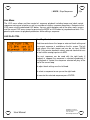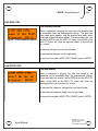
1
// K2579 // Step Sequencer
User Manual
Hardware Version B
Firmware Version 1.0x
June 20, 2011
Kilpatrick Audio
// K2579 // Step Sequencer
2p
Introduction
The K2579 is a compact and powerful programmable two-part modular sequencer and performance
instrument. It supports simultaneous input, output and control via analog and MIDI connections and
nearly all programming and performance parameters can be modified in real-time. More than just a
simple step sequencer, the K2579 allows sequences to be built, arranged, modified and controlled
seamlessly. The entire unit is programmed through a simple interface consisting of an LCD, two
knobs and seven buttons. Eight front-panel jacks allow patching the CV/GATE output pairs, inputting
clock and reset signals, and inputting two continuous voltages which can be mapped onto various
performance parameters for real-time control from other modules.
Up to 16 sequences of 16 steps each (per part) can be loaded at once. Sequences can be chained
together, looped or completely controlled manually. The unit features a built-in clock for convenience,
but can also sync to an external analog clock pulse or MIDI clock. Using the MIDI functionality
requires a K1600 MIDI Converter or other breakout device for interfacing the MIDI signals.
The K2579 Step Sequencer brings new potential to the world of modular synthesis by offering new
ways of making music. Building on the success of the K4815 Pattern Generator, the K2579 is a step
sideways. Where the K4815 excels in fast creation of rhythms and melodies based on intelligently
designed ingredients, the K2579 offers user control over every note and function, and also offers twonote polyphony by supporting two parts per sequence.
All master system settings and up to eight songs (a group of 16 sequences) are stored internally and
automatically restored when the unit is powered on, making the unit quick and easy to use.
User Manual
Hardware Version B
Firmware Version 1.0x
June 20, 2011
© 2010 Kilpatrick Audio
// K2579 // Step Sequencer
3p
Features
•
•
•
•
•
•
•
•
•
•
•
•
•
•
•
•
•
•
•
•
•
•
•
•
Eurorack (3U) form factor – 14HP width
High contrast LCD screen with amber backlight.
Fully-programmable unit with two knobs and seven buttons.
Driven by a powerful 32-bit processor.
Two-part 16 step sequencer with 16 sequences per song.
Internal non-volatile (EEPROM) storage for 8 songs.
Automatic store / recall of system parameters at power up.
Most recent song loaded automatically at power up.
Individual step length control allows any kind of rhythm to be created.
Per-sequence control of start, length, loop count, playback direction, etc.
Per-sequence part control of notes, gate length, scale, note span, transposition, etc.
Each part assignable to a separate MIDI channel for polyphonic or multi-timbral playback.
MIDI keyboard-controlled sequence start and transposition.
Key trigger mode for momentary playback of sequences.
Selectable key map with CC-controlled map swapping for use with small MIDI controllers.
Live playback mode for real-time overrides of various playback parameters.
Factory-trimmed CV outputs with super high-accuracy DAC.
Clock and Reset inputs for controlling the sequencer from analog clock source.
MOD CV inputs for controlling various playback parameters. (programmable assignment)
Dual CV / GATE output for driving oscillators / envelope generators or other modules.
MIDI I/O of most functions available via internal 10 pin Kilpatrick Audio MIDI header.
Requires +12V (110mA) and -12V (50mA) - 16 pin Doepfer-style power cable used
Designed and made in Canada using high quality parts.
Warranty: 1 year
User Manual
Hardware Version B
Firmware Version 1.0x
June 20, 2011
© 2010 Kilpatrick Audio
// K2579 // Step Sequencer
4p
Installation and Setup
When installing the K2579 in your modular system, pay close attention to the pinout and direction of
the 16-pin power input cable. The K2579 contains protection against reverse connection but please
double-check the cable before switching on the unit. The warranty does not cover damage caused
by wrong installation.
If you are using the module with another MIDI device using the internal MIDI cable, connect a 10 pin
ribbon cable between the two units. (This cable is included with the K1600 MIDI Converter) In this
case also observe the correct cable direction.
Warning: DO NOT plug the MIDI cable into the power port, or vice versa.
Output Voltage Trim
The voltage trim on the outputs is factory calibrated into a 100K ohm load. But depending on your
setup you might need to adjust it if the scale tuning is wrong with your oscillators. The multi-turn trim
pot supplied on each output can adjust the tuning over a significant range. Use the CV CALIBRATE
screen to test the DAC outputs with your oscillators and adjust if necessary.
User Manual
Hardware Version B
Firmware Version 1.0x
June 20, 2011
© 2010 Kilpatrick Audio
// K2579 // Step Sequencer
5p
Physical Installation
You should install the unit in your modular system using all four screw holes. The unit is designed to
be mounted properly to avoid damage to the internal parts when plugging or unplugging cables, or
adjusting the controls.
Connection Warnings
The CV outputs are buffered, low impedance (100 ohm) outputs designed to drive oscillator
1V/octave inputs with minimal error. You should not attempt to sum the CV outputs with passive
multiples. Doing so will not harm the unit, but will likely not result in the behaviour you expect. Do not
feed external voltages into the outputs.
The gate outputs are 1000 ohm outputs and should not have voltages fed into them from other units.
You should be able to sum the signals using passive multiples, but buffered mixers are a better
choice for achieving proper mixing of signals. Do not feed external voltages into the outputs.
Clock, reset and mod input jacks are designed for voltages in the range of 0-5V. They are tolerant of
voltages from -12V to +12V. Proper triggering of clock and reset inputs are 0V = off, 5V = on. MOD
inputs detect proportional voltages from 0-5V. If your signal source falls outside this range you should
use a CV scaling / offset module to adjust the voltage to be within this range.
User Manual
Hardware Version B
Firmware Version 1.0x
June 20, 2011
© 2010 Kilpatrick Audio
// K2579 // Step Sequencer
Panel Layout and Controls
User Manual
Hardware Version B
Firmware Version 1.0x
June 20, 2011
© 2010 Kilpatrick Audio
6p
// K2579 // Step Sequencer
7p
First Usage
When you first install and power up the K2579 you'll likely want to get something happening right
away. The easiest way to generate notes is to select a part using the PART menu and cursor over to
last page. Turn the right parameter knob to select part randomize and press ENTER. This will seed
the pattern with random notes and rests.
Part Transform – Part Menu
To transform parts: invert, retrograde, randomize, clear
Fig. 4 – Randomize Transform
Select the operation (right knob) to perform on the selected
part / sequence and press ENTER to execute.
Press the LIVE button and select a tempo with the left parameter knob. Select the sequence you just
randomized with the right knob if it's not already selected in the playback bar. Press ENTER to select
the sequence. Press PLAY/PAUSE to start playback. CV and GATE signals should be produced on
one or both of the outputs.
Live Play Control – Live Menu
Adjust the clock tempo or select external clock source. (left
knob)
Fig. 5 – Live Play Control
User Manual
Select a sequence to cue up or play instantly. (right knob)
When stopped, selecting a sequence and pressing ENTER will
make it ready for playback. When playing, selecting a
sequence will cue it to start at the end of the currently playing
sequence. Press ENTER to execute.
Hardware Version B
Firmware Version 1.0x
June 20, 2011
© 2010 Kilpatrick Audio
// K2579 // Step Sequencer
8p
Live Control of Playback
You can jam right away by using the arrow keys to use the other live control screens. Use the LIVE
SEQ CTRL menu to adjust the gate length and sequence playback direction. Use the LIVE STEP
CTRL to affect the start position and length of the playing sequences.
Live Sequence Control
Fig. 6 – Live Sequence Control
Adjust the gate time for both parts (left knob) and the
playback direction (right knob) in real-time. This gives you
convenient hands-on control without the need for a MIDI
controller or external voltage source.
Live Step Control
Fig. 7 – Live Step Control
User Manual
Adjust the start position (left knob) and sequence playback
length (right knob) in real time. Try taking a small sequence
fragment and then moving the start point, or shortening and
lengthening it to make interesting sounds.
Hardware Version B
Firmware Version 1.0x
June 20, 2011
© 2010 Kilpatrick Audio
// K2579 // Step Sequencer
9p
Sequencer Architecture
This section is intended to familiarize you with the internal data structure and layout of the sequencer.
With this knowledge you will better understand what can be accomplished. The K2579 Step
Sequencer is a two part sequencer. Steps are controlled together for both parts, meaning that the
direction, step length, start and length of each sequence playback and the chaining together and
looping of different sequences are performed on both parts. However for each step played, two
different CV/GATE signals are generated. You can select different scales, octave spans and the
transposition for each part, and the gate time for each part can be separately controlled. Also, each
part can be sent to a different MIDI channel making multi-timbral performances possible.
Sequences
A sequence contains 16 steps of two parts for a total of 32 notes. A sequence also contains settings
such as which step should be played first, the sequence length, the length of each step, the number of
times the sequence should loop before moving to another sequence, and so on. A sequence also
contains two parts which define the actual notes (or rests) played back for each of the two parts.
A sequence contains the following data:
•
Sequence Start – The step number (1-16) where playback starts.
•
Sequence Length – The number of steps (1-16) played back.
•
Sequence Step Length – Steps can last from 1-31 clock ticks. (or the default) The default is
equal to the current clock divider setting in the SYSTEM menu.
•
Sequence Loop – The number of loops (0-15) before the next sequence is played.
•
Sequence Direction – A sequence can be played back in different ways:
◦ bkwd – Counts down from the start for length number of steps. Wraps around from step 1 to
16 and beyond if the length takes the count below step 1.
◦ pong – Counts up and down in a ping-pong mode. The endpoints are not repeated. Wraps
around as in bkwd and fwd.
◦ rand – Plays up to length number of random steps. Only chooses steps that fall between start
and start + length – 1. This allows the specific range of random steps to be chosen.
◦ fwd – Counts up from the start for length steps. Wraps around from step 16 to 1 and beyond if
the length takes the count above step 16.
•
Sequence Next – After the sequence is played once plus the number of loops, this sets the next
sequence to be played. The default is the current sequence so that the sequence will repeat
forever regardless of the loop setting.
•
Part Data – Data for parts 1 and 2.
User Manual
Hardware Version B
Firmware Version 1.0x
June 20, 2011
© 2010 Kilpatrick Audio
// K2579 // Step Sequencer
10p
A part contains the following data:
•
Step Notes – Each of the 16 steps for a part can be set to the following:
◦ Notes – A four octave + 1 (49 values) range of notes is possible. The available notes are
based on the currently selected scale and octave span.
◦ RAND – Each time the step plays a note will be randomly chosen. The current scale and
octave span will be observed when selecting the random note.
◦ NONE – The step will not be played. If the gate time is set high enough the previous step will
carry over (tie) to this step.
◦ REST – Previous note will be stopped but no new note will be started.
•
Gate Length – The gate length affects how long notes will play on each step. The setting can
range from 1-48 clock ticks. This setting affects all steps in the part.
•
Scale – The scale affects which notes are available when entering or editing notes for a part. The
selected scale can also non-destructively affect playback of existing sequences by causing notes
to be quantized to a different scale than that used while entering them. This only affects playback
and does not modify the underlying notes stored in the part. Note names shown on the LCD are
always related to C being the starting note, however the part can be transposed into any key.
Available scales are as follows:
◦ chromatic
- C, C#, D, D#, E, F, F#, G, G#, A, A#, B, C
◦ major
- C, D, E, F, G, A, B, C
◦ nat minor (natural)
- C, D, Eb, F, G, Ab, Bb, C
◦ har minor (harmonic)
- C, D, Eb, F, G, Ab, B, C
◦ whole
- C, D, E, F#, G#, A#
◦ pentatonic
- C, D, E, G, A
◦ diminished
- C, D, Eb, F, F#, G#, A, B
◦ level
- semitones from 0-48 (4 octaves + 1)
•
Octave Span – The octave span sets the number of octaves from 1-4 that will be played. This is
used when entering or editing notes for a part. It can also be used when playing back a sequence
to reduce the range of notes. This is performed non-destructively. Notes outside the currently set
range will be transposed to fit within the range.
•
Note Offset – The note offset is used to transpose all notes in a part up or down 12 semitones.
User Manual
Hardware Version B
Firmware Version 1.0x
June 20, 2011
© 2010 Kilpatrick Audio
// K2579 // Step Sequencer
11p
Songs
A song is simply a collection of 16 sequences that can be loaded or saved together. It contains no other
special settings. All playback parameters and other settings are stored system-wide. You can load or
save up to 8 songs into the internal memory. When loaded, a song will overwrite all sequence and part
parameters.
System Parameters
The system parameters contain settings related to the MIDI and analog I/O, the master clock tempo and
other settings that are used for overall system setup. Unlike a computer-based sequencer, parameters
such as tempo and MIDI channels are not stored in a song. This is intentional as a song is intended to
hold sequence parameters and notes only, whereas the system parameters are used for high-level
setup of the entire module and how it interacts with a modular system. Once you get your system
configured, you can freely load and save songs without worrying about reconfiguring each song for your
system. Songs can therefore be used as scratchpads of ideas that can quickly be loaded and used.
System parameters are auto-saved periodically after being changed. If you make changes to system
settings please wait at least 10 seconds before powering off the unit to ensure that the latest settings
were saved. The currently loaded song number will be automatically loaded at power up, however the
loaded song must be saved manually as the song currently running is stored in RAM during use.
The system parameters are as follows:
•
Tempo / EXT Clock – Sets the internal clock tempo or sets if an external clock should be used.
•
Clock Divider – Sets how many clock ticks are required to advance the sequence one step.
•
Reset Mode – Sets whether resetting playback will restart the song or the current sequence.
•
MOD1 CV Assignment – Assigns the destination for the MOD 1 CV input.
•
MOD2 CV Assignment - Assigns the destination for the MOD 2 CV input.
•
Live Audition – Sets whether live auditioning of notes is on or off during editing.
•
MIDI Part 1 Channel – Selects the TX/RX channel for part 1.
•
MIDI Part 2 Channel – Selects the TX/RX channel for part 2.
•
Key Transpose Mode – Selects which parts should be transposed when using a MIDI keyboard.
•
Key Trigger Mode – Selects whether MIDI notes will trigger a momentary sequence playback.
•
Key Map – Selects one of two keyboard maps.
•
LCD Contrast – Sets the LCD screen contrast.
User Manual
Hardware Version B
Firmware Version 1.0x
June 20, 2011
© 2010 Kilpatrick Audio
// K2579 // Step Sequencer
12p
Analog Inputs and Outputs
The sequencer contains 8 analog jacks on the front panel, 4 inputs and 4 outputs.
RESET IN and CLOCK IN
The RESET IN and CLOCK IN jacks provide a method of clocking the sequencer from an LFO (Low
Frequency Oscillator) or other clock source. The RESET IN jack provides the same function as pressing
the RESET button or sending a MIDI start message. Depending on the RESET MODE selected, the
rising edge of a pulse on this input will cause either the sequence or the entire song to be restarted.
The CLOCK IN jack accepts +5V pulses and generates clock ticks internally when the LIVE menu has
the clock tempo set to EXT CLK. The LED next to the CLOCK IN jack will pulse once per tick when
using CLOCK IN with an analog clock source or once per step with a MIDI or internal clock source.
Valid voltages: 0V idle, +5V (rising edge) to clock or reset.
Voltages from -12V to +12V are internally clamped to this range.
MOD 1 IN and MOD 2 IN
Variable voltages can be fed into the MOD 1 IN and MOD 2 IN jacks to modulate and override live
performance parameters inside the sequencer. Voltages from 0V to +5V are sampled on each jack
rapidly, allowing fast control from other modules. The MOD1 CV ASSIGN and MOD2 CV ASSIGN
screens in the SYSTEM menu are used to select the parameter controlled by each input. The range and
meaning of the values is similar to the MIDI CC inputs. The MOD CTRL CANCEL option in either the
SYSTEM menu or in the LIVE menus can be used to cancel the current override settings.
Valid voltages: 0V to +5V continuous. All parameters range from 0V (lowest value) to +5V (highest
value).
Other voltages from -12V to +12V are internally clamped to this range.
Possible modulation assignments are:
•
•
•
•
•
•
•
•
none – the MOD CV input is not assigned
seq next – selects a sequence from 1-16
seq start – overrides the sequence start position from 1-16
seq len – overrides the sequence length from 1-16 steps
seq run/stop – causes the sequencer to run (+5V) or stop (0V)
gate 1 time – overrides the part 1 gate time – offers a range of 1-32 ticks
gate 2 time – overrides the part 2 gate time – offers a range of 1-32 ticks
seq direction – overrides the direction (+5V) when in fwd or bkwd mode
User Manual
Hardware Version B
Firmware Version 1.0x
June 20, 2011
© 2010 Kilpatrick Audio
// K2579 // Step Sequencer
13p
CV 1 OUT and CV 2 OUT
The CV outputs create tuning or modulation voltages for use with oscillators or other modules. They
generate note outputs for part 1 and part 2 respectively. The outputs are factory trimmed to 1V/octave
and support a range of six octaves from -3V to +3V. The outputs are derived from high precision 12-bit
DACs and buffered. The outputs are low impedance (100 ohms) for good tuning accuracy with pitch
oscillators. Summing with other signals should be done with buffered mixers and not passive multiples.
External sources of voltage should not be input into the CV outputs.
GATE 1 OUT and GATE 2 OUT
The GATE outputs are used for controlling envelope generators. They generate gate outputs for part 1
and part 2 respectively. They outputs are 0V (off) or +5V (on) and have a 1000 ohm output impedance.
External sources of voltage should not be input into the GATE outputs.
User Manual
Hardware Version B
Firmware Version 1.0x
June 20, 2011
© 2010 Kilpatrick Audio
// K2579 // Step Sequencer
14p
Menu Layout
Most functions on the K2579 are performed by navigating to one of the menu screens and either
adjusting or executing a function. The layout of the menus and navigation keys is designed to make it
fast to access the most common functions and easy to remember where each screen is located.
Menus are divided into two major groups: main menus, and the live menu. Main menus include the
SEQUENCE, PART 1, PART 2 and SYSTEM menus. The LIVE menu is a special menu used for
real-time control of playback parameters and control overrides. You can jump back and forth between
a main menu and the LIVE menus without losing your place in each. This is designed to allow quick
access to performance parameters while editing.
Main Menus
SEQUENCE
•
•
•
•
•
•
•
•
SEQ START
SEQ LENGTH
SEQ STEP LENGTH
SEQ LOOP
SEQ DIRECTION
SEQ NEXT
SEQ COPY
SEQ CLEAR
PART 1 / PART 2 (one per part) SYSTEM
•
•
•
•
•
•
•
PART NOTE SET
PART GATE LENGTH
PART SCALE
PART OCTAVE SPAN
PART NOTE OFFSET
PART COPY
PART TRANSFORM
•
•
•
•
•
•
•
•
•
•
•
•
•
•
•
•
•
SONG LOAD
SONG SAVE
SONG CLEAR
MOD CTRL CANCEL
CLOCK DIVIDER
RESET MODE
MOD1 CV ASSIGN
MOD2 CV ASSIGN
LIVE AUDITION
MIDI PART 1 CHANNEL
MIDI PART 2 CHANNEL
KEY TRANSPOSE
KEY TRIGGER
KEY MAP
LCD CONTRAST
CV CALIBRATE
SYSTEM RESET
LIVE Menu
LIVE
•
•
•
LIVE PLAY CTRL
LIVE SEQ CTRL
LIVE STEP CTRL
User Manual
Hardware Version B
Firmware Version 1.0x
June 20, 2011
© 2010 Kilpatrick Audio
// K2579 // Step Sequencer
15p
Sequence Menus
The sequence menu is navigated to by using the MODE button. These screens allow you to modify
sequence playback parameters. For most screens the left parameter knob is used for selecting which
of the 16 sequences are modified. The right parameter knob is used for adjusting the currently
selected parameter value.
SEQ START
Sequence Start Position
Fig. 8 – Sequence Start
The sequence start position can be set to any of the 16
steps. When a sequence begins playing the selected step will
be played first. (Note that this may not be the case for random
step mode) The start position affects the range of steps
played.
To adjust the current editing sequence use the left knob.
To adjust the start step for the selected sequence use the right
knob.
SEQ LENGTH
Sequence Length
Fig. 9 – Sequence Length
The sequence length affects how many steps will play, (fwd,
bkwd, or pong mode) or the range of steps used. (random dir
mode) If the start plus the length would wrap around, the
sequencer will automatically do this during playback.
To adjust the current editing sequence use the left knob.
To adjust the sequence length use the right knob.
User Manual
Hardware Version B
Firmware Version 1.0x
June 20, 2011
© 2010 Kilpatrick Audio
// K2579 // Step Sequencer
16p
SEQ STEP LENGTH
Sequence Step Length
Fig. 10 – Sequence Step Length
The length of each sequence step can be controlled. The
length is measured in the number of clock ticks required to
advance the sequencer to the next step. By default, steps use
the DIV value which is equal to the system clock divider
setting. (defaults to 6, or sixteenth notes in MIDI) You can
override this setting with a value from 1-31.
To adjust the currently selected step use the left knob.
To adjust the length of the currently selected step use the right
knob.
SEQ LOOP
Sequence Loop Count
Fig. 11 – Sequence Loop Count
Each sequence will play at least one time when it is selected
or arrived at from another sequence. The sequence loop
count can be set from 0-15 times. This is the number of times
the sequence will be looped in addition to the first playback
instance.
To adjust the current editing sequence use the left knob.
To adjust the number of loop counts use the right knob.
User Manual
Hardware Version B
Firmware Version 1.0x
June 20, 2011
© 2010 Kilpatrick Audio
// K2579 // Step Sequencer
17p
SEQ DIRECTION
Sequence Direction
The sequencer can play back each sequence in one of four
different direction modes: fwd, bkwd, pong or rand. They
work as follows:
Fig. 12 – Sequence Direction
•
•
•
•
bkwd – Plays backwards from the start step down for
length number of steps.
pong – Plays up and down in a ping-pong mode. The
end points are not repeated.
rand – Plays steps in a random order. The range of
steps used is set by the start and length controls.
fwd – Plays forward from the start step up for length
number of steps.
For the pong mode to work correctly the sequence must play
for at least two times before moving to another sequence.
To adjust the current editing sequence use the left knob.
To adjust the direction mode use the right knob.
User Manual
Hardware Version B
Firmware Version 1.0x
June 20, 2011
© 2010 Kilpatrick Audio
// K2579 // Step Sequencer
18p
SEQ NEXT
Sequence Next
Fig. 13 – Sequence Next
The sequencer will play a sequence from 1-16 times
depending on the loop setting. Then it will either play the
same sequence again (the default) or move to a different
sequence. The sequence next control allows sequences to
be chained together to form songs.
To adjust the current editing sequence use the left knob.
To adjust the next sequence to play use the right knob.
SEQ COPY
Sequence Copy
Fig. 14 – Sequence Copy
A sequence and all its parameters can be copied to another
sequence. This is useful for making variations, backing up
ideas before editing and so on. A copied sequence will
overwrite all sequence and part data at the new location.
To adjust the current editing (and source) sequence use the
left knob.
To select the destination for the copy operation use the right
knob.
To execute the copy press ENTER.
User Manual
Hardware Version B
Firmware Version 1.0x
June 20, 2011
© 2010 Kilpatrick Audio
// K2579 // Step Sequencer
19p
SEQ CLEAR
Sequence Clear
Fig. 15 – Sequence Clear
All sequence and part data can be cleared back to the default
state. This will only clear the current sequence and all other
15 sequences currently loaded will not be affected. However if
the sequence to be cleared is part of a playback chain, the
next sequence will have to be reset after clearing for the song
to play as before.
To select the sequence to be cleared use the left knob.
To clear the selected sequence press ENTER.
User Manual
Hardware Version B
Firmware Version 1.0x
June 20, 2011
© 2010 Kilpatrick Audio
// K2579 // Step Sequencer
20p
Part Menus
The PART menus are navigated to by using the MODE button. These screens allow you to modify
parameters related to one of the two parts. You can select either PART 1 or PART 2 by pressing the
MODE button. The currently selected sequence (selectable via the SEQUENCE or LIVE menus) is
edited, and this number is shown on the display whenever you are in part editing mode. Normally the
right parameter knob is used for editing the selected parameter. The left knob is also used in the note
setting screen to select the current step.
Note that the example screens below show PART 1, but the same screens are available for PART 2.
PART NOTE SET
Part Note Set
The notes for each part are set using this screen. The current
editing sequence must be already set in either the
SEQUENCE or LIVE menus.
Fig. 16 – Part Note Setting
The step and note can be controlled using the left and right
knobs respectively. All steps can be set even if they are not
currently set to play by the start and length setting or
overrides. The available notes depend on the current scale
and octave span settings. The note names are always
referenced to C as the starting note, and the sharps and flats
shown are based on the members of the currently selected
scale.
In addition to the currently available scale notes, a step can be
set to RAND to cause a random note to be chosen each time
the step is played, NONE to allow a previous step with a long
gate time to continue, or REST to stop the previous note and
insert silence.
The LIVE AUDITION setting in the SYSTEM menu affects
whether editing will cause the notes to sound or not.
To select the step to edit use the left knob.
To edit the note for the selected step use the right knob.
User Manual
Hardware Version B
Firmware Version 1.0x
June 20, 2011
© 2010 Kilpatrick Audio
// K2579 // Step Sequencer
21p
PART GATE LENGTH
Part Gate Length
Fig. 17 – Part Gate Length
The gate length for each part can be adjusted. This affects all
notes in the current part. The gate length is measured in clock
ticks. The CLOCK DIVIDER setting defaults to 6 which equals
sixteenth notes for the MIDI or internal clock. The gate length
controls when the gate will be turned off after a note is started.
The gate length can be adjusted from 1-48 ticks.
To adjust the gate length use the right knob.
PART SCALE
Part Scale
Fig. 18 – Part Scale
The scale can be adjusted for each part to limit the notes that
can be selected while editing, and also to quantize an existing
sequence into a different scale during playback. Scales are
represented as starting at C but the output can be transposed
into any key. Note that micro-tonal and scales that do not
repeat on octaves are not supported by the K2579.
Adjusting the scale will non-destructively affect the notes
played back without modifying the underlying notes.
Available scales are as follows:
• chromatic
• major
• nat minor (natural minor)
• har minor (harmonic minor)
• whole
• pentatonic
• diminished
• level
User Manual
Hardware Version B
Firmware Version 1.0x
June 20, 2011
© 2010 Kilpatrick Audio
// K2579 // Step Sequencer
22p
PART OCTAVE SPAN
Part Octave Span
Fig. 19 – Part Octave Span
The octave span affects the number of octaves that can be
edited or played. It is controllable from 1 to 4. It affects which
notes are available while editing steps, but also affects the
playback of existing sequences by reducing the note range
during playback.
Adjusting the octave span will non-destructively affect the
notes played back without modifying the underlying notes.
To adjust the octave span use the right knob.
PART NOTE OFFSET
Part Note Offset
Fig. 20 – Part Note Offset
The note offset is used for transposing the part. This affects
both playback and editing and can be used to move a
sequence into a different key. The range of offset is -12 to +12
semitones.
To adjust the offset use the right knob.
PART COPY
Part Copy
Fig. 21 – Part Copy
A part can be copied to the other part in the same sequence.
This is useful for making two related parts from the same
original sequence of notes. Copying a part will overwrite all
part data in the destination part.
To select the copy direction use the right knob.
To execute the copy press ENTER.
User Manual
Hardware Version B
Firmware Version 1.0x
June 20, 2011
© 2010 Kilpatrick Audio
// K2579 // Step Sequencer
23p
PART TRANSFORM
Part Transform
Fig. 22 – Part Transform
Parts can have their notes transformed several different way,
or seeded with random notes and rests. This is useful for
quickly developing sequences and transforming an existing
sequence to make interesting variations.
The available transformations are:
• invert – turn the part notes upside-down by inverting all
the intervals
• retrograde – flip the part notes from front to back by
swapping notes (i.e. step 16 becomes 1, 1 becomes
16, etc.)
• randomize – fill the part with random notes and rests
• clear – clear the part to a blank starting state – This is
different than clearing a sequence in that all notes are
made as rests and no note is placed on the first step.
To select a transformation use the right knob.
To execute the selected transformation press ENTER.
User Manual
Hardware Version B
Firmware Version 1.0x
June 20, 2011
© 2010 Kilpatrick Audio
// K2579 // Step Sequencer
24p
System Menu
The SYSTEM menu includes such things as song loading and saving, clock divider setting, (tempo /
external clock) the MOD input assignments, MIDI channels, keyboard control behaviour and so on.
These are automatically saved regularly in the background. This allows you to configure how you
would like to use the system, and then load and save groups of sequences as needed.
SONG LOAD
Song Load
Fig. 23 – Song Load
Songs can be loaded from the internal memory. Loading only
takes a second and replaces all sequence and part data with
that from the loaded song. Songs can also be loaded using
the MIDI Song Select command which is the same as using
this command.
To select a song to load use the right knob. The currently
loaded song is shown with an asterisk (*) beside the song
number.
To load the selected song press ENTER.
SONG SAVE
Song Save
Fig. 24 – Song Save
Songs can be saved to internal memory for later use. The
internal memory holds data even after power off. Saving the
song overwrites the selected song with the current sequence
and part data.
To select the song to save to, use the right knob. The currently
loaded song is shown with an asterisk (*) beside the song
number.
To save the current song to the selected song slot press
ENTER.
User Manual
Hardware Version B
Firmware Version 1.0x
June 20, 2011
© 2010 Kilpatrick Audio
// K2579 // Step Sequencer
25p
SONG CLEAR
Song Clear
Fig. 25 – Song Clear
To clear the current sequence and part data to the defaults,
use the song clear screen. This can be useful for starting a
fresh song or for clearing the internal memory by saving a
cleared song over unwanted songs in the internal memory.
To clear the current sequence and part data press ENTER.
MOD CTRL CANCEL
Mod Control Cancel
Fig. 26 – Mod Control Cancel
When using MIDI control change messages or MOD CV
inputs to override various playback parameters it may become
necessary to reset the controllers to their default (not
overridden) state.
To reset all controllers to the default value press ENTER.
CLOCK DIVIDER
Clock Divider
Fig. 27 – Clock Divider
The clock divider affects how both the internal and external
clock sources are divided down to generate the step rate. The
internal clock and MIDI clocks operate on a 24 ppq timebase,
meaning that for each beat (quarter note) 24 pulses are
generated.
Using a clock with a higher rate than the internal step rate is
important for the proper operation of the gate time and step
length parameters. The clock divider can be set from 1/1 to
1/24.
To set the clock divider use the right knob.
User Manual
Hardware Version B
Firmware Version 1.0x
June 20, 2011
© 2010 Kilpatrick Audio
// K2579 // Step Sequencer
26p
RESET MODE
Reset Mode
Fig. 28 – Reset Mode
When using the reset button, MIDI start command or analog
reset input, the sequencer will either restart the song or the
current sequence. The behaviour is configurable based on
specific requirements.
To select the reset mode use the right knob.
MOD 1/2 CV ASSIGN
Mod 1/2 CV Assign
There are two MOD inputs which can each accept an analog
voltage from 0-5V. Each input can be assigned to an override
parameter similar to the MIDI CC inputs.
Fig. 29 – Mod CV Assign
Note that these controls override the settings in the sequence
and part menus. They do not affect the internal settings and
their values are not stored when the song is saved.
The assignments that can be made for the MOD inputs
are:
• none – The CV input is not assigned.
• seq next – The next sequence (1-16) is set by a
voltage.
• seq start – The start step position is set by a voltage.
• seq length – The sequence length is set by a voltage.
• run/stop – A voltage of 5V will start the sequencer, a
voltage of 0V will stop it.
• gate 1 time – Part 1 gate time will be set by a voltage.
• gate 2 time – Part 2 gate time will be set by a voltage.
• seq direction – A voltage of 5V will reverse the
playback direction.
To set a MOD CV input assignment use the right knob.
User Manual
Hardware Version B
Firmware Version 1.0x
June 20, 2011
© 2010 Kilpatrick Audio
// K2579 // Step Sequencer
27p
LIVE AUDITION
Live Audition
Fig. 30 – Live Audition
When editing notes for each part it is possible to hear a
preview of the note right away without playing the sequence.
This feature is on by default but can be turned off for blind
editing.
To set the live audition setting use the right knob.
MIDI PART 1/2
MIDI Part Channel Assign
Fig. 31 – MIDI Part Channel Assign
The MIDI channel for each of the two parts can be set to any
of the 16 MIDI channels. Setting both parts to the same
channel permits polyphonic output for synthesizers that
support it.
MIDI input for controlling the sequencer from a keyboard or
computer is always received on both selected MIDI channels.
To set the MIDI channel for a part use the right knob.
KEY TRANSPOSE
Key Transpose
Fig. 32 – Key Transpose
A MIDI keyboard or other source can be used to transpose a
sequence up or down. The key transpose screen selects
which parts the transpose affects. Either none, part 1, part 2
or both can be selected.
To set the key transpose mode use the right knob.
User Manual
Hardware Version B
Firmware Version 1.0x
June 20, 2011
© 2010 Kilpatrick Audio
// K2579 // Step Sequencer
28p
KEY TRIGGER
Key Trigger
Fig. 33 – Key Trigger
The key trigger mode allows the sequence to be momentarily
started and stopped with a MIDI keyboard. In latch mode a
sequence select key will start a sequence playing or cue it for
playing on the next loop. In momentary mode a sequence will
be start and stopped as the key is pressed and released.
Trigger mode can be set to either: latch or momentary.
To set the key trigger mode use the right knob.
KEY MAP
Key Map
Fig. 34 – Key Map
The key map affects which keys on the keyboard are mapped
to which functions. See the section on MIDI control for more
information as to the actual key assignments. Key maps A and
B have the transpose functions and sequence select functions
reversed.
The selected key map will be available by default. Sending
control change 1 (modulation wheel) with a value of 64-127
will swap to the other key map. This allows all functions to be
accessible even on small (25 key) keyboard controllers
typically used in performance. When the map is swapped in
this way the display will show the swapped map. e.g.: “A>B”
means that key map is normally A but swapped to B by the
mod wheel control change.
To select the default key map use the right knob.
User Manual
Hardware Version B
Firmware Version 1.0x
June 20, 2011
© 2010 Kilpatrick Audio
// K2579 // Step Sequencer
29p
LCD CONTRAST
LCD Contrast
Fig. 35 – LCD Contrast
The LCD screen should not normally require contrast
adjustment. However it is possible to adjust it. The setting is
stored as part of the system setting and will be recalled
automatically at power-on.
Note that this menu can also be accessed at any time by
pressing MODE and ENTER together. This is useful if the
current setting prevents the screen from being read.
To adjust the LCD contrast use the right knob.
CV CALIBRATE
CV Calibrate
To make calibrating the CV outputs or oscillator inputs easier it
is possible to generate known voltages. The outputs are
factory calibrated and should not need adjustment.
Fig. 36 – CV Calibrate
To adjust CV 1 output voltage use the left knob.
To adjust CV 2 output voltage use the right knob.
To use the sequencer normally exit this screen.
User Manual
Hardware Version B
Firmware Version 1.0x
June 20, 2011
© 2010 Kilpatrick Audio
// K2579 // Step Sequencer
30p
SYSTEM RESET
System Reset
All system settings can be reset to the factory defaults. This
does not affect any sequence or part data currently loaded,
nor does it affect any saved songs.
Fig. 37 – System Reset
User Manual
To reset the system settings press ENTER.
Hardware Version B
Firmware Version 1.0x
June 20, 2011
© 2010 Kilpatrick Audio
// K2579 // Step Sequencer
31p
Live Menu
The LIVE menu allows real-time control of sequence playback including tempo and clock control,
sequence cueing and selection as well as overrides of various sequence parameters. Navigate to the
LIVE menu using the dedicated LIVE button. You can switch between one of the other menu screens
and the current LIVE menu screen by pressing the MODE or LIVE button to jump back and forth. This
permits quick access to playback parameters while editing a sequence.
LIVE PLAY CTRL
Live Play Control
Fig. 38 – Live Play Control
Real-time control over the tempo or external clock setting and
the current sequence is available on the this screen. The left
knob affects the clock tempo and can be set from 20-250
BPM. Fully counter-clockwise selects external clock which can
be fed into the analog input or via MIDI.
The next sequence can be cued with the right knob. If
playback is stopped, the sequence is selected immediately. If
the playback is started, the sequence selected will play at the
end of the current loop.
To adjust clock settings use the left knob.
To select a sequence to cue up use the right knob.
To execute the selected sequence press ENTER.
User Manual
Hardware Version B
Firmware Version 1.0x
June 20, 2011
© 2010 Kilpatrick Audio
// K2579 // Step Sequencer
32p
LIVE SEQ CTRL
Live Sequence Control
Fig. 39 – Live Sequence Control
While a sequence is playing, the gate time and direction can
be overridden from the programmed settings. The gate time
affects both parts together, and the direction only works when
using fwd or bkwd direction modes. These overrides can also
be sent by MIDI or with the MOD CV inputs. Using MIDI or the
MOD CV inputs will show the override values in real-time on
this screen.
To override the gate time use the left knob.
To override the direction use the right knob.
To cancel all overrides (MOD CTRL CANCEL) press ENTER.
LIVE STEP CTRL
Live Step Control
Fig. 40 – Live Step Control
While a sequence is playing, the start and length of the
sequence can be overridden from the programmed settings.
These overrides can also be sent by MIDI or with the MOD CV
inputs. Using MIDI or the MOD CV inputs will show the
override values in real-time on this screen.
To override the sequence start position use the left knob.
To override the sequence length use the right knob.
To cancel all overrides (MOD CTRL CANCEL) press ENTER.
User Manual
Hardware Version B
Firmware Version 1.0x
June 20, 2011
© 2010 Kilpatrick Audio
// K2579 // Step Sequencer
33p
Programming Sequences
Programming a sequence involves selecting notes for each of up to 16 steps per sequence. Up to 16
sequences can be loaded at once and are grouped together into a song. Songs contain no other
common parameters other than the group of sequences. Each sequence can select which sequence
will play after it, allowing sequences to be chained or looped as desired.
A sequence contains two parts, each with 16 steps. Each part can store parameters about the scale
and range of notes used, as well as the transposition. Each sequence can store parameters about the
starting point and length of the sequence, how many times the sequence loops before moving to
another sequence, as well as the playback direction.
To program a sequence from scratch, first select the desired sequence in the LIVE menu and start it
playing. Use the PART menus for each part to adjust the notes and other part parameters. You can
edit the notes in real-time and hear them the next time the loop repeats. If the part is not repeating
use the SEQ NEXT menu and select the current sequence as the next sequence to make it loop
forever.
Live and Blind Editing
The LIVE AUDITION setting in the SYSTEM menu selects whether notes are sounded when editing
steps of a part. With LIVE AUDITION on, the notes will be sounded whenever the step or note pot is
selected, allowing previewing of the notes already programmed, as well as the newly selected notes.
This is useful if you prefer editing when the playback is stopped.
With the LIVE AUDITION setting set to off you can freely edit sequences while the same or another
sequence is playing.
Scale and Octave Span
Notes can be set up in any scale or octave span setting and then transformed to another scale without
affecting the underlying note values. This is useful for quickly changing the tonality of a sequence
without having to modify each note value. You can also adjust the octave span which effectively
collapses the range of a sequence by transposing down notes that fall outside the chosen range.
Copying and Transformations
Sequences and parts can be copied easily to assist in creating variations of a sequence or using a
sequence as a starting point for a new tune.
Transformations enable notes for a part within a sequence to be created or transformed. You can seed a
part with random notes and rests, invert a part by flipping intervals, and create a retrograde by swapping
note positions to create a backward version of a part.
User Manual
Hardware Version B
Firmware Version 1.0x
June 20, 2011
© 2010 Kilpatrick Audio
// K2579 // Step Sequencer
34p
MIDI Control
The K2579 Step Sequencer has a power MIDI implementation that can be used to control various
functions in real-time from a MIDI keyboard or computer. It can also be used to drive MIDI
synthesizers for playback. Although most functions are accessible via the front-panel analog
connections, MIDI offers functions not possible otherwise. To access the MIDI signals requires either
a K1600 or compatible MIDI breakout board. Free plans are available from Kilpatrick Audio if you wish
to build your own low-cost unit.
MIDI can also be used to update the contents of the song memories and edit song parameters. For
details on how to do this and to express your interest in software built for this purpose please contact
Kilpatrick Audio.
MIDI IN and OUT Channels
The MIDI channels to be used by the K2579 can be set in the MIDI PART 1 and 2 screens. This sets the
channel on which each part is transmitted. If set to the same channel, both parts will be sent together.
This could cause problems for some instruments if both parts have overlapping notes, therefore it is
suggested to use different channels for each part.
MIDI is always received on either part 1 or part 2 channel and there is no distinction between them. You
can send messages to the K2579 on either channel with the same result.
MIDI Clock Control
The sequencer will always send MIDI clock messages if it is receiving analog or MIDI clock ticks or
generating its own clock. The clock is sent even when the unit is stopped. MIDI start, continue and stop
messages are generated and recognized. The start message will reset the sequencer as per the RESET
MODE setting, either resetting the entire song or resetting the current sequence only.
Song Select
The MIDI song select message will automatically load a song from the internal memory. Songs 0-7 (1-8)
are recognized.
User Manual
Hardware Version B
Firmware Version 1.0x
June 20, 2011
© 2010 Kilpatrick Audio
// K2579 // Step Sequencer
35p
Control Change Messages
The sequencer will respond to control change messages and allow various control overrides to be set
which override live playback parameters. Some of these functions are also accessible in the LIVE
menus. Unsupported control changes messages are echoed through the unit to be used by instruments.
Supported Control Change Messages
Control Change (CC)
Action
Swap Key Map: 1 (mod wheel)
Swaps the key map from the current setting to the other key map.
Value: 0-63 = normal
Value: 64-127 = swapped
Next Sequence: 20
Selects the sequence that should be played next. This takes effect at the end of
the current playing sequence.
Value: 0-127 = sequence 1-16
Seq Start Override: 21
Overrides the start position for the sequence.
Value: 0-127 = position 1-16
Seq Length Override: 22
Overrides the length of the sequence.
Value: 0-127 = position 1-16
Run / Stop: 23
Controls the sequencer run/stop function.
Value: 0-63 = stop
Value: 64-127 = run
Gate 1 Time Override: 24
Overrides the gate time for part 1.
Value: 0-127 = gate time of 1-32 ticks
Gate 2 Time Override: 25
Overrides the gate time for part 2.
Value: 0-127 = gate time of 1-32 ticks
Mod Control Cancel: 31
Cancels all overrides and reverts to the sequence / part settings.
Value: 0-63 = no effect
Value: 64-127 = cancel
Direction Override: 64 (damper)
Flips the playback direction when using either fwd or bkwd direction type.
Value: 0-63 = no effect
Value: 64-127 = flip
User Manual
Hardware Version B
Firmware Version 1.0x
June 20, 2011
© 2010 Kilpatrick Audio
// K2579 // Step Sequencer
36p
Note Messages / Key Mappings
Functions of the sequencer can be controlled from a MIDI keyboard. There are two selectable
keyboard maps which define the functions. Map A is the default and contains all functions mapped
over four octaves. In either map, sequences can be selected, the clock can be controlled, control
overrides can be cancelled, and the pitch of the sequence can be transposed up or down. Key map B
limits the transposition to +11 semitones instead of +12, but is otherwise functionally identical.
To support operation with small (25 key) keyboards such as portable MIDI controllers the modulation
wheel (CC #1) can be used to swap key maps during performance. This enables quick swapping of
the functions without having to press the keyboard octave up and down buttons repeatedly. When the
mod wheel is set from 64-127 (top 50%) the key map will be swapped.
For the full maps of key map A and B please see the following page.
Key Trigger Mode
Key trigger mode affects how the sequence select keys affect sequence starting and stopping. In latch
mode the sequences are started or cued up with the sequence select keys. In momentary mode letting
off a sequence select key will stop playback.
Note Message Transmission
Notes are sent in response to steps being played on part 1 and 2. These notes reflect the current CV
output voltage. Notes are shifted up to be within a more suitable range for most synthesizers, but in
addition to the normal four octave editing range, the output can be further shifted up or down by an
octave in each direction.
User Manual
Hardware Version B
Firmware Version 1.0x
June 20, 2011
© 2010 Kilpatrick Audio
// K2579 // Step Sequencer
MIDI Note Key Maps
Fig. 41 – Key Maps
User Manual
Hardware Version B
Firmware Version 1.0x
June 20, 2011
© 2010 Kilpatrick Audio
37p
// K2579 // Step Sequencer
38p
SYSEX Control
System exclusive messages are used for special Kilpatrick Audio functions such as software updates
and debugging. The internal memory can be read and written using special SYSEX commands. This
can enable external librarian software to send and receive complete song files to and from the unit. For
more information and details on how to use this please contact Kilpatrick Audio. We can offer
information and helpful design guidelines to customers who wish to create their own compatible
software.
Future software revisions may enable other control and editing functions via SYSEX as per customer
requests. Please contact us if you have specific requirements.
User Manual
Hardware Version B
Firmware Version 1.0x
June 20, 2011
© 2010 Kilpatrick Audio
// K2579 // Step Sequencer
39p
Internal Connector Pinouts
To assist in making correct connections, and to aid in the creation of compatible adaptor circuits, the
internal pin headers are documented here. Please note that X3 is a factory setup connector only and
should not be used. Both X1 and X2 connectors are 0.100" pitch pin headers. Standard ribbon cables
can be connected.
X2 – MIDI/Test Connector:
1.
2.
3.
4.
5.
6.
7.
8.
9.
10.
Fig. 42 – Internal Connectors
GND
GND
GND
GND
TEST (input – future)
MIDI TX (output to ext. module)
N/C
MIDI RX (input from ext. module)
+3.3V / +5V aux. power out
+3.3V / +5V aux. power out
X1 – Power:
1.
2.
3.
4.
5.
6.
7.
8.
9.
10.
11.
12.
13.
14.
15.
16.
-12V input
-12V input
GND
GND
GND
GND
GND
GND
+12V input
+12V input
N/C
N/C
N/C
N/C
N/C
N/C
Software Update
Should changes to the K2579 firmware be released, such as feature enhancements or bug fixes, new
firmware can be loaded using special PC or Mac software supplied by Kilpatrick Audio. Please
contact Kilpatrick Audio if you have any questions about software updates or wish to file a bug report.
Updates require the use of a K1600 MIDI Converter or other MIDI interface board to connect the
K2579 to the MIDI ports on your computer. Alternately Kilpatrick Audio can update your firmware for
the cost of transport to/from Kilpatrick Audio.
Support and Additional Information
Please contact Kilpatrick Audio with additional questions about the K2579 Step Sequencer. We will do
our best to help you make the most of your step sequencer and welcome your suggestions as to
software improvements or ideas for features on new products. Contact: [email protected]
User Manual
Hardware Version B
Firmware Version 1.0x
June 20, 2011
© 2010 Kilpatrick Audio
// K2579 // Step Sequencer
K2579 Step Sequencer
MIDI IMPLEMENTATION CHART ver.1.0
40p
2011-06-20
Function
Transmitted
Recognized
Remarks
Basic
Channel
Default
Changed
none
1-16 (configured)
none
1-16 (configured)
Use SYSTEM menu to
select MIDI channels.
Mode
Default
Messages
Altered
X
X
X
X
X
X
24-96
24-72
Transmit range depends
on part settings.
X
X
Ignored in all modes.
X
X
X
X
Ignored in all modes.
Pitch Bend
O
O
Echoed for selected MIDI
channels.
Control Change
O
O
Echos non-implemented
CCs. Responds to
selected CCs. See CC
manual section.
Prog
Change True #
O
O
Echoed for selected MIDI
channels.
System Exclusive
O
O
See documentation for
SYSEX usage.
System
Common
Song Position
Song Select
Tune Request
O
X
X
O
O
X
System
Realtime
Clock
Commands
O
O
O
O
Aux
Messages
Local On/Off
All Notes Off
Active Sensing
System Reset
X
X
X
X
X
X
X
X
Note Number
Velocity
After
Touch
Keys
Ch's
Software update specification available upon request. Implemented by Kilpatrick
Audio update software as supplied to customers.
Notes
User Manual
Hardware Version B
Firmware Version 1.0x
June 20, 2011
© 2010 Kilpatrick Audio