1
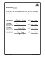
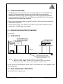
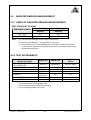
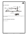
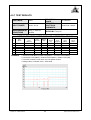
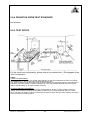
Equipment
:
ADAPTER
Test Model No.
:
41A9734 FRU P/N: 41A9732 (Brand Name: lenovo),
PA-1121-04(Brand Name: LITEON, TOSHIBA)
Multiple Listing
:
PA-1121-04XX
(The “X” in the models could be defined as 0-9, A-Z, - or blank
for marketing differentiation.)
Applicant
:
Lite-On Technology Corporation
Test Report No.
:
CE961112A03
We, Advance Data Technology Corp., declare that the equipment above has been tested in our facility and
found compliance with the requirement limits of applicable standards. The test record, data evaluation and
Equipment Under Test (EUT) configurations represented herein are true and accurate under the standards
herein specified.
EN 55022: 2006, Class B
EN 55024: 1998+A1: 2001+A2: 2003
EN 61000-3-2: 2006, Class D
IEC 61000-4-2: 2001 ED.1.2
EN 61000-3-3:1995+A1:2001+A2:2005
IEC 61000-4-3: 2006 ED.3.0
IEC 61000-4-4: 2004 ED.2.0
CISPR 22: 2005, Class B
IEC 61000-4-5: 2005 ED.2.0
AS/NZS CISPR 22: 2006, Class B
IEC 61000-4-6: 2006 ED.2.2
IEC 61000-4-8: 2001 ED.1.1
IEC 61000-4-11: 2004 ED.2.0
In accordance with the council directive 2004/108/EC.
Kenny Meng / Deputy Manager Linkou EMC / RF Lab. ADT CORP.
No. 47, 14th Ling, Chia Pau Tsuen, Lin Kou Hsiang, Taipei Hsien, 244
Taiwan, R.O.C. Tel: 886-2-26052180 Fax: 886-2-26051924
http://www.adt.com.tw E-Mail: [email protected]
CE EMC TEST REPORT
REPORT NO.: CE961112A03
MODEL NO.: PA-1121-04XX, 41A9734 FRU P/N: 41A9732
RECEIVED: Nov. 12, 2007
TESTED: Nov. 13 ~ 15, 2007
ISSUED: Nov. 17, 2007
APPLICANT: Lite-On Technology Corporation
ADDRESS: 90,Chien I Road, Chung Ho, Taipei Hsien,
Taiwan, R.O.C.
ISSUED BY: Advance Data Technology Corporation
LAB LOCATION: No. 47, 14th Ling, Chia Pau Tsuen, Lin Kou
Hsiang 244, Taipei Hsien, Taiwan, R.O.C.
This test report consists of 66 pages in total. It may be duplicated completely for legal use with the
approval of the applicant. It should not be reproduced except in full, without the written approval of
our laboratory. The client should not use it to claim product endorsement by TAF, A2LA or any
government agencies. The test results in the report only apply to the tested sample.
Report No.: CE961112A03
1
Report Format Version 2.0.9
Table of Contents
1
CERTIFICATION ............................................................................................. 5
2
2.1
SUMMARY OF TEST RESULTS..................................................................... 7
MEASUREMENT UNCERTAINTY .................................................................. 9
3
3.1
3.2
3.3
3.4
3.4.1
3.4.2
GENERAL INFORMATION ........................................................................... 10
GENERAL DESCRIPTION OF EUT.............................................................. 10
DESCRIPTION OF TEST MODES................................................................ 10
GENERAL DESCRIPTION OF APPLIED STANDARDS ................................11
DESCRIPTION OF SUPPORT UNITS.......................................................... 12
FOR EMISSION TEST .................................................................................. 12
FOR HARMONICS / FLICKER / IMMUNITY TEST ....................................... 13
4
4.1
4.1.1
4.1.2
4.1.3
4.1.4
4.1.5
4.1.6
4.1.7
4.1.8
4.2
4.2.1
4.2.2
4.2.3
4.2.4
4.2.5
4.2.6
4.2.7
4.3
4.3.1
4.3.2
4.3.3
4.3.4
4.3.5
4.3.6
4.3.7
4.4
4.4.1
4.4.2
4.4.3
4.4.4
4.4.5
4.4.6
EMISSION TEST........................................................................................... 14
CONDUCTED EMISSION MEASUREMENT ................................................ 14
LIMITS OF CONDUCTED EMISSION MEASUREMENT.............................. 14
TEST INSTRUMENTS .................................................................................. 14
TEST PROCEDURE ..................................................................................... 15
DEVIATION FROM TEST STANDARD ......................................................... 15
TEST SETUP ................................................................................................ 15
EUT OPERATING CONDITIONS.................................................................. 15
TEST RESULTS (1) ...................................................................................... 16
TEST RESULTS (2) ...................................................................................... 18
RADIATED EMISSION MEASUREMENT ..................................................... 20
LIMITS OF RADIATED EMISSION MEASUREMENT................................... 20
TEST INSTRUMENTS .................................................................................. 20
TEST PROCEDURE ..................................................................................... 21
DEVIATION FROM TEST STANDARD ......................................................... 21
TEST SETUP ................................................................................................ 22
EUT OPERATING CONDITIONS.................................................................. 22
TEST RESULTS............................................................................................ 23
HARMONICS CURRENT MEASUREMENT ................................................. 25
LIMITS OF HARMONICS CURRENT MEASUREMENT............................... 25
TEST INSTRUMENTS .................................................................................. 25
TEST PROCEDURE ..................................................................................... 26
DEVIATION FROM TEST STANDARD ......................................................... 26
TEST SETUP ................................................................................................ 26
EUT OPERATING CONDITIONS.................................................................. 26
TEST RESULTS............................................................................................ 27
VOLTAGE FLUCTUATION AND FLICKS MEASUREMENT ......................... 28
LIMITS OF VOLTAGE FLUCTUATION AND FLICKS MEASUREMENT ....... 28
TEST INSTRUMENTS .................................................................................. 28
TEST PROCEDURE ..................................................................................... 28
DEVIATION FROM TEST STANDARD ......................................................... 29
TEST SETUP ................................................................................................ 29
EUT OPERATING CONDITIONS.................................................................. 29
Report No.: CE961112A03
2
Report Format Version 2.0.9
4.4.7
TEST RESULTS............................................................................................ 30
5
5.1
5.2
5.3
5.4
5.4.1
5.4.2
5.4.3
5.4.4
5.4.5
5.4.6
5.5
IMMUNITY TEST .......................................................................................... 31
GENERAL DESCRIPTION............................................................................ 31
GENERAL PERFORMANCE CRITERIA DESCRIPTION ............................. 32
EUT OPERATING CONDITION .................................................................... 32
ELECTROSTATIC DISCHARGE IMMUNITY TEST (ESD)............................ 33
TEST SPECIFICATION................................................................................. 33
TEST INSTRUMENTS .................................................................................. 33
TEST PROCEDURE ..................................................................................... 33
DEVIATION FROM TEST STANDARD ......................................................... 34
TEST SETUP ................................................................................................ 35
TEST RESULTS............................................................................................ 36
RADIATED, RADIO-FREQUENCY, ELECTROMAGNETIC FIELD IMMUNITY
TEST (RS)..................................................................................................... 37
TEST SPECIFICATION................................................................................. 37
TEST INSTRUMENTS .................................................................................. 37
TEST PROCEDURE ..................................................................................... 38
DEVIATION FROM TEST STANDARD ......................................................... 38
TEST SETUP ................................................................................................ 39
TEST RESULTS............................................................................................ 40
ELECTRICAL FAST TRANSIENT/BURST IMMUNITY TEST (EFT) ............. 41
TEST SPECIFICATION................................................................................. 41
TEST INSTRUMENTS .................................................................................. 41
TEST PROCEDURE ..................................................................................... 41
DEVIATION FROM TEST STANDARD ......................................................... 42
TEST SETUP ................................................................................................ 42
TEST RESULTS............................................................................................ 43
SURGE IMMUNITY TEST............................................................................. 44
TEST SPECIFICATION................................................................................. 44
TEST INSTRUMENTS .................................................................................. 44
TEST PROCEDURE ..................................................................................... 45
DEVIATION FROM TEST STANDARD ......................................................... 45
TEST SETUP ................................................................................................ 45
TEST RESULTS............................................................................................ 46
IMMUNITY TO CONDUCTED DISTURBANCES INDUCED BY RF FIELDS
(CS) 47
TEST SPECIFICATION................................................................................. 47
TEST INSTRUMENTS .................................................................................. 47
TEST PROCEDURE ..................................................................................... 48
DEVIATIN FOR TEST STANDARD ............................................................... 48
TEST SETUP ................................................................................................ 49
TEST RESULTS............................................................................................ 50
POWER FREQUENCY MAGNETIC FIELD IMMUNITY TEST...................... 51
TEST SPECIFICATION................................................................................. 51
TEST INSTRUMENTS .................................................................................. 51
TEST PROCEDURE ..................................................................................... 51
DEVIATION FROM TEST STANDARD ......................................................... 52
TEST SETUP ................................................................................................ 52
5.5.1
5.5.2
5.5.3
5.5.4
5.5.5
5.5.6
5.6
5.6.1
5.6.2
5.6.3
5.6.4
5.6.5
5.6.6
5.7
5.7.1
5.7.2
5.7.3
5.7.4
5.7.5
5.7.6
5.8
5.8.1
5.8.2
5.8.3
5.8.4
5.8.5
5.8.6
5.9
5.9.1
5.9.2
5.9.3
5.9.4
5.9.5
Report No.: CE961112A03
3
Report Format Version 2.0.9
5.9.6
5.10
5.10.1
5.10.2
5.10.3
5.10.4
5.10.5
5.10.6
TEST RESULTS............................................................................................ 53
VOLTAGE DIP/SHORT INTERRUPTIONS/VOLTAGE VARIATIONS (DIP)
IMMUNITY TEST .......................................................................................... 54
TEST SPECIFICATION................................................................................. 54
TEST INSTRUMENTS .................................................................................. 54
TEST PROCEDURE ..................................................................................... 54
DEVIATION FROM TEST STANDARD ......................................................... 54
TEST SETUP ................................................................................................ 55
TEST RESULTS............................................................................................ 56
6
PHOTOGRAPHS OF THE TEST CONFIGURATION.................................... 57
7
APPENDIX - INFORMATION ON THE TESTING LABORATORIES............. 66
Report No.: CE961112A03
4
Report Format Version 2.0.9
1 CERTIFICATION
PRODUCT: ADAPTER
MODEL NO.: PA-1121-04XX(Brand Name: LITEON, TOSHIBA)
(The “X” in the models could be defined as 0-9, A-Z, - or blank for marketing
differentiation.)
APPLICANT:
TESTED:
TEST ITEM:
STANDARDS:
41A9734 FRU P/N: 41A9732 (Brand Name: lenovo)
Lite-On Technology Corporation
Nov. 13 ~ 15, 2007
ENGINEERING SAMPLE
EN 55022: 2006, Class B
EN 55024: 1998+A1: 2001
EN 61000-3-2: 2006, Class D
+A2: 2003
EN 61000-3-3: 1995+A1: 2001
IEC 61000-4-2: 2001 ED.1.2
+A2: 2005
IEC 61000-4-3: 2006 ED.3.0
IEC 61000-4-4: 2004 ED.2.0
IEC 61000-4-5: 2005 ED.2.0
CISPR 22: 2005, Class B
IEC 61000-4-6: 2006 ED.2.2
AS/NZS CISPR 22: 2006,
IEC 61000-4-8: 2001 ED.1.1
Class B
IEC 61000-4-11: 2004 ED.2.0
The above equipment has been tested by Advance Data Technology
Corporation, and found compliance with the requirement of the above
standards.
Approval signature-on next page
Report No.: CE961112A03
5
Report Format Version 2.0.9
CERTIFICATION-Continued
The test record, data evaluation & Equipment Under Test (EUT) configurations
represented herein are true and accurate accounts of the measurements of the
sample’s EMC characteristics under the conditions specified in this report.
PREPARED BY
:
,
DATE: Nov. 17, 2007
,
DATE: Nov. 17, 2007
,
DATE: Nov. 17, 2007
,
DATE: Nov. 17, 2007
(Irene Hou/ Specialist )
TECHNICAL
ACCEPTANCE
:
Responsible for EMI
TECHNICAL
ACCEPTANCE
( Ken Liu / Deputy Manager )
:
Responsible for EMS
APPROVED BY
( Andy Cheng / Senior Engineer )
:
( Kenny Meng / Deputy Manager )
Report No.: CE961112A03
6
Report Format Version 2.0.9
2 SUMMARY OF TEST RESULTS
The EUT has been tested according to the following specifications:
Standard
EN 55022: 2006,
Class B
EMISSION
Test Type
Result
Conducted Test
Meets Class B Limit
PASS Minimum passing margin is
–10.10 dB at 0.562 MHz
Radiated Test
Meets Class B Limit
PASS Minimum passing margin is
–2.99 dB at 219.70 MHz
CISPR 22: 2005,
Class B
AS/NZS CISPR 22:
2006, Class B
Remarks
EN 61000-3-2:2006,
Class D
Harmonic current
PASS Meets Class D Limit
emissions
EN 61000-3-3:1995+
A1: 2001 +A2: 2005
Voltage
fluctuations &
flicker
Report No.: CE961112A03
PASS Meets the requirements.
7
Report Format Version 2.0.9
IMMUNITY (EN 55024: 1998+A1: 2001+A2: 2003)
Standard
Test Type
Result
Remarks
Electrostatic
Meets the requirements of
IEC 61000-4-2: 2001
PASS
discharge
ED.1.2
Performance Criterion B
immunity test
Radiated,
Meets the requirements of
IEC 61000-4-3: 2006 radio-frequency,
PASS
Performance Criterion A
ED.3.0
electromagnetic
field immunity test
Electrical fast
Meets the requirements of
IEC 61000-4-4: 2004
transient / burst
PASS
ED.2.0
Performance Criterion A
immunity test.
Meets the requirements of
IEC 61000-4-5: 2005 Surge immunity
PASS
ED.2.0
test
Performance Criterion A
Immunity to
conducted
Meets the requirements of
IEC 61000-4-6: 2006 disturbances,
PASS
ED.2.2
Performance Criterion A
induced by
radio-frequency
fields
Power frequency
Meets the requirements of
IEC 61000-4-8: 2001
magnetic field
PASS
ED.1.1
Performance Criterion A
immunity test.
IEC 61000-4-11:
2004 ED.2.0
Report No.: CE961112A03
Voltage dips, short
interruptions and
voltage variations
immunity tests
8
Meets the requirements of
Voltage Dips:
i.) >95% reduction Performance Criterion A
PASS ii.) 30% reduction –
Performance Criterion A
Voltage Interruptions:
i) >95% reduction –
Performance Criterion B
Report Format Version 2.0.9
2.1 MEASUREMENT UNCERTAINTY
Where relevant, the following measurement uncertainty levels have been estimated
for tests performed on the EUT as specified in CISPR 16-4-2:
This uncertainty represents an expanded uncertainty expressed at approximately
the 95% confidence level using a coverage factor of k=2.
Measurement
Conducted emissions
Uncertainty
2.45 dB
Radiated emissions
3.97 dB
Report No.: CE961112A03
9
Report Format Version 2.0.9
3 GENERAL INFORMATION
3.1 GENERAL DESCRIPTION OF EUT
PRODUCT
ADAPTER
MODEL NO.
PA-1121-04XX, 41A9734 FRU P/N: 41A9732
POWER SUPPLY
Switching
Rating: refer to the below
Power Cord:
Non-shielded DC (1.8 m) with one core
DATA CABLE
SUPPLIED
N/A
NOTE:
1.
The EUT is an ADAPTER (AC 3Pin) with two models, which are identical with
each other in all aspects except for their rating differences only, as follows :
Brand
LITEON
TOSHIBA
lenovo
Model No.
Rating
PA-1121-04XX
Ø AC I/P: 100-240V, 2.0A, 50-60Hz.
Ø DC O/P: +19V/ 6.3A
41A9734 FRU P/N: 41A9732
Ø AC I/P: 100-240V, 1.8A, 50-60Hz.
Ø DC O/P: +19.5V/ 6.15A
Note: The “X” in the model: PA-1121-04XX could be defined as 0-9, A-Z, - or blank for marketing
differentiation.
2.
For a more detailed features description, please refer to the manufacturer's
specifications or the User's Manual.
3.2 DESCRIPTION OF TEST MODES
The EUT was tested using the above models. The worst emission level was found
when tested on model no.: 41A9734 FRU P/N: 41A9732. Therefore the final test
modes are as follows:
Test Item
Conducted Test
Radiated, Harmonic,
flicker, Immunity Test
Report No.: CE961112A03
Test Mode
Model No.
Mode 1
41A9734 FRU P/N: 41A9732
Mode 2
PA-1121-04
Mode 1
41A9734 FRU P/N: 41A9732
10
Remark
Full Load
Report Format Version 2.0.9
3.3 GENERAL DESCRIPTION OF APPLIED STANDARDS
The EUT is a kind of ITE equipment and, according to the specifications of the
manufacturers, must comply with the requirements of the following standards:
EN 55022: 2006,Class B
EN 61000-3-2: 2006, Class D
EN 61000-3-3: 1995+A1: 2001
+A2: 2005
CISPR 22: 2005, Class B
AS/NZS CISPR 22: 2006, Class B
EN 55024: 1998+A1: 2001+A2: 2003
IEC 61000-4-2: 2001 ED.1.2
IEC 61000-4-3: 2006 ED.3.0
IEC 61000-4-4: 2004 ED.2.0
IEC 61000-4-5: 2005 ED.2.0
IEC 61000-4-6: 2006 ED.2.2
IEC 61000-4-8: 2001 ED.1.1
IEC 61000-4-11: 2004 ED.2.0
All tests have been performed and recorded as per the above standards.
Report No.: CE961112A03
11
Report Format Version 2.0.9
3.4 DESCRIPTION OF SUPPORT UNITS
The EUT has been tested as an independent unit together with other necessary
accessories or support units. The following support units or accessories were used to
form a representative test configuration during the tests.
3.4.1 FOR EMISSION TEST
NO.
1
PRODUCT
DUMMY LOAD
BRAND
ADT
MODEL NO.
L19A
SERIAL NO.
L2-010008
FCC ID
N/A
Note: One non-shielded AC 3-Pin power cord (1.8m) was connected to EUT.
TEST CONFIGURATION
DUMMY LOAD
EUT
Report No.: CE961112A03
12
Report Format Version 2.0.9
3.4.2 FOR HARMONICS / FLICKER / IMMUNITY TEST
NO.
PRODUCT
BRAND
MODEL NO.
SERIAL NO.
FCC ID
1
DUMMY LOAD
ADT
L19A
L2-010005
N/A
2
Multimeter
YFE
YF-370A
N/A
N/A
Note: One non-shielded AC 3-Pin power cord (1.8m) was connected to EUT.
Test Configuration
Multimeter
Report No.: CE961112A03
DUMMY
LOAD
13
EUT
Report Format Version 2.0.9
4 EMISSION TEST
4.1 CONDUCTED EMISSION MEASUREMENT
4.1.1 LIMITS OF CONDUCTED EMISSION MEASUREMENT
TEST STANDARD: EN 55022
Class A (dBuV)
Class B (dBuV)
FREQUENCY (MHz)
Quasi-peak Average Quasi-peak Average
0.15 - 0.5
79
66
66 - 56
56 - 46
0.50 - 5.0
73
60
56
46
5.0 - 30.0
73
60
60
50
NOTE:
(1) The lower limit shall apply at the transition frequencies.
(2) The limit decreases in line with the logarithm of the frequency in the range of 0.15
to 0.50 MHz.
(3) All emanations from a class A/B digital device or system, including any network of
conductors and apparatus connected thereto, shall not exceed the level of field
strengths specified above.
4.1.2 TEST INSTRUMENTS
DESCRIPTION &
MODEL NO.
SERIAL NO.
MANUFACTURER
ROHDE & SCHWARZ Test
ESHS 30
828765/002
Receiver
ROHDE & SCHWARZ Artificial
ESH3-Z5
835239/001
Mains Network (for EUT)
LISN With Adapter (for EUT)
AD10
C09Ada-001
ROHDE & SCHWARZ Artificial
ESH3-Z5
835239/002
Mains Network (for peripherals)
Software
ADT_Cond_V7.3.5
NA
Software
ADT_ISN_V7.3.5
NA
RF cable (JYEBAO)
5D-FB
Cable-C09.01
SUHNER Terminator
65BNC-5001
E1-010789
(For ROHDE & SCHWARZ LISN)
CALIBRATED
UNTIL
Jul. 30, 2008
Feb. 26, 2008
Feb. 26, 2008
Mar. 13, 2008
NA
NA
Mar. 01, 2008
May 17, 2008
NOTE: 1. The calibration interval of the above test instruments is 12 months and the
calibrations are traceable to NML/ROC and NIST/USA.
2. The test was performed in ADT Shielded Room No. 9.
3. The VCCI Site Registration No. C-1312.
Report No.: CE961112A03
14
Report Format Version 2.0.9
4.1.3 TEST PROCEDURE
a. The EUT was placed 0.4 meters from the conducting wall of the shielded room
with EUT being connected to the power mains through a line impedance
stabilization network (LISN). Other support units were connected to the power
mains through another LISN. The two LISNs provide 50 Ohm/ 50uH of coupling
impedance for the measuring instrument.
b. Both lines of the power mains connected to the EUT were checked for maximum
conducted interference.
c. The frequency range from 150 kHz to 30 MHz was searched. Emission levels
under (Limit - 20dB) were not recorded.
4.1.4 DEVIATION FROM TEST STANDARD
No deviation
4.1.5 TEST SETUP
V e r t ic a l G r o u n d
R e fe re n c e P la n e
T e s t R e c e iv e r
EUT
40cm
80cm
L IS N
H o r iz o n t a l G r o u n d
R e fe re n c e P la n e
N o te : 1 .S u p p o rt u n its w e re c o n n e c te d to s e c o n d L IS N .
2 . B o t h o f L I S N s ( A M N ) a r e 8 0 c m f r o m E U T a n d a t le a s t 8 0 c m
f r o m o t h e r u n it s a n d o t h e r m e t a l p l a n e s s u p p o r t u n i t s .
For the actual test configuration, please refer to the related item – Photographs of the
Test Configuration.
4.1.6 EUT OPERATING CONDITIONS
Set the EUT on full resistor load.
Report No.: CE961112A03
15
Report Format Version 2.0.9
4.1.7 TEST RESULTS (1)
TEST MODE
Mode 1
6dB BANDWIDTH
9 kHz
INPUT POWER
230Vac, 50 Hz
PHASE
Line (L)
ENVIRONMENTAL
CONDITIONS
25deg. C, 58% RH,
1004hPa
TESTED BY: Jerry Huang
Freq.
Corr.
Reading Value
[MHz]
0.150
0.349
0.474
0.645
1.189
12.689
18.479
Factor
(dB)
0.30
0.30
0.30
0.30
0.30
0.96
1.24
[dB (uV)]
Q.P.
AV.
40.71
42.44
39.64
38.95
36.58
40.74
41.44
-
No
1
2
3
4
5
6
7
Emission
Level
[dB (uV)]
Q.P.
AV.
41.01
42.74
39.94
39.25
36.88
41.70
42.68
-
Limit
Margin
[dB (uV)]
Q.P.
AV.
66.00 56.00
58.99 48.99
56.44 46.44
56.00 46.00
56.00 46.00
60.00 50.00
60.00 50.00
(dB)
Q.P.
-24.99
-16.25
-16.50
-16.75
-19.12
-18.30
-17.32
AV.
-
REMARKS: 1. Q.P. and AV. are abbreviations of quasi-peak and average individually.
2. "-": The Quasi-peak reading value also meets average limit and
measurement with the average detector is unnecessary.
3. The emission levels of other frequencies were very low against the limit.
4. Margin value = Emission level - Limit value
5. Correction factor = Insertion loss + Cable loss
6. Emission Level = Correction Factor + Reading Value.
Report No.: CE961112A03
16
Report Format Version 2.0.9
TEST MODE
Mode 1
6dB BANDWIDTH
9 kHz
INPUT POWER
230Vac, 50 Hz
PHASE
Neutral (N)
ENVIRONMENTAL
CONDITIONS
25deg. C, 58% RH,
1004hPa
TESTED BY: Jerry Huang
Freq.
Corr.
Reading Value
[MHz]
0.357
0.474
0.642
0.967
13.121
18.998
Factor
(dB)
0.20
0.20
0.20
0.20
0.89
1.08
[dB (uV)]
Q.P.
AV.
38.59
37.78
38.77
37.38
40.55
41.48
-
No
1
2
3
4
5
6
Emission
Level
[dB (uV)]
Q.P.
AV.
38.79
37.98
38.97
37.58
41.44
42.56
-
Limit
Margin
[dB (uV)]
Q.P.
AV.
58.79 48.79
56.44 46.44
56.00 46.00
56.00 46.00
60.00 50.00
60.00 50.00
(dB)
Q.P.
-20.00
-18.46
-17.03
-18.42
-18.56
-17.44
AV.
-
REMARKS: 1. Q.P. and AV. are abbreviations of quasi-peak and average individually.
2. "-": The Quasi-peak reading value also meets average limit and
measurement with the average detector is unnecessary.
3. The emission levels of other frequencies were very low against the limit.
4. Margin value = Emission level - Limit value
5. Correction factor = Insertion loss + Cable loss
6. Emission Level = Correction Factor + Reading Value.
Report No.: CE961112A03
17
Report Format Version 2.0.9
4.1.8 TEST RESULTS (2)
TEST MODE
Mode 2
6dB BANDWIDTH
9 kHz
INPUT POWER
230Vac, 50 Hz
PHASE
Line (L)
ENVIRONMENTAL
CONDITIONS
25deg. C, 58% RH,
1004hPa
TESTED BY: Jerry Huang
Freq.
Corr.
Reading Value
[MHz]
0.171
0.390
0.450
0.562
0.789
1.287
12.878
Factor
(dB)
0.30
0.30
0.30
0.30
0.30
0.30
0.97
[dB (uV)]
Q.P.
AV.
42.60
44.74
42.35
45.60
44.49
43.22
42.94
-
No
1
2
3
4
5
6
7
Emission
Level
[dB (uV)]
Q.P.
AV.
42.90
45.04
42.65
45.90
44.79
43.52
43.91
-
Limit
Margin
[dB (uV)]
Q.P.
AV.
64.91 54.91
58.06 48.06
56.88 46.88
56.00 46.00
56.00 46.00
56.00 46.00
60.00 50.00
(dB)
Q.P.
-22.01
-13.02
-14.23
-10.10
-11.21
-12.48
-16.09
AV.
-
REMARKS: 1. Q.P. and AV. are abbreviations of quasi-peak and average individually.
2. "-": The Quasi-peak reading value also meets average limit and
measurement with the average detector is unnecessary.
3. The emission levels of other frequencies were very low against the limit.
4. Margin value = Emission level - Limit value
5. Correction factor = Insertion loss + Cable loss
6. Emission Level = Correction Factor + Reading Value.
Report No.: CE961112A03
18
Report Format Version 2.0.9
TEST MODE
Mode 2
6dB BANDWIDTH
9 kHz
INPUT POWER
230Vac, 50 Hz
PHASE
Neutral (N)
ENVIRONMENTAL
CONDITIONS
25deg. C, 58% RH,
1004hPa
TESTED BY: Jerry Huang
Freq.
Corr.
Reading Value
[MHz]
0.168
0.387
0.510
0.618
1.016
12.316
16.649
Factor
(dB)
0.20
0.20
0.20
0.20
0.20
0.84
1.03
[dB (uV)]
Q.P.
AV.
38.82
43.64
43.22
43.70
43.80
42.62
38.07
-
No
1
2
3
4
5
6
7
Emission
Level
[dB (uV)]
Q.P.
AV.
39.02
43.84
43.42
43.90
44.00
43.46
39.10
-
Limit
Margin
[dB (uV)]
Q.P.
AV.
65.06 55.06
58.13 48.13
56.00 46.00
56.00 46.00
56.00 46.00
60.00 50.00
60.00 50.00
(dB)
Q.P.
-26.04
-14.29
-12.58
-12.10
-12.00
-16.54
-20.90
AV.
-
REMARKS: 1. Q.P. and AV. are abbreviations of quasi-peak and average individually.
2. "-": The Quasi-peak reading value also meets average limit and
measurement with the average detector is unnecessary.
3. The emission levels of other frequencies were very low against the limit.
4. Margin value = Emission level - Limit value
5. Correction factor = Insertion loss + Cable loss
6. Emission Level = Correction Factor + Reading Value.
Report No.: CE961112A03
19
Report Format Version 2.0.9
4.2
RADIATED EMISSION MEASUREMENT
4.2.1 LIMITS OF RADIATED EMISSION MEASUREMENT
TEST STANDARD: EN 55022
Class A (at 10m)
FREQUENCY (MHz)
dBuV/m
NOTE:
Class B (at 10m)
dBuV/m
30 – 230
40
30
230 - 1000
47
37
(1) The lower limit shall apply at the transition frequencies.
(2) Emission level (dBuV/m) = 20 log Emission level (uV/m).
(3) All emanations from a class A/B digital device or system, including any network
of conductors and apparatus connected thereto, shall not exceed the level of field
strengths specified above.
4.2.2 TEST INSTRUMENTS
DESCRIPTION &
MANUFACTURER
ROHDE & SCHWARZ
TEST RECEIVER
CHASE BILOG Antenna
ADT. Turn Table
ADT. Tower
Software
ANRITSU RF Switches
WOKEN RF cable
MODEL NO.
SERIAL NO.
CALIBRATED
UNTIL
ESVS10
846285/012
Aug. 06, 2008
CBL6112A
2331
TT100
0201
AT100
0201
ADT_Radiate
NA
d_V7.6.15
MP59B
M32159
8D
CABLE-ST8-01
Sep. 13, 2008
NA
NA
NA
Mar. 29, 2008
Mar. 29, 2008
NOTE: 1. The calibration interval of the above test instruments is 12 months. And the calibrations
are traceable to NML/ROC and NIST/USA.
2. The test was performed in ADT Open Site No. 8.
3. The VCCI Site Registration No. R-877.
Report No.: CE961112A03
20
Report Format Version 2.0.9
4.2.3 TEST PROCEDURE
a. The EUT was placed on the top of a rotating table 0.8 meters above the ground
at a 10-meter open field site. The table was rotated 360 degrees to determine the
position of the highest radiation.
b. The EUT was set 10 meters away from the interference-receiving antenna, which
was mounted on the top of a variable-height antenna tower.
c. The antenna is a broadband antenna, and its height is varied from one meter to
four meters above the ground to determine the maximum value of the field
strength. Both horizontal and vertical polarization of the antenna are set to make
the measurement.
d. For each suspected emission, the EUT was arranged to its worst case and then
the antenna was tuned to heights from 1 meter to 4 meters and the turn table
was turned from 0 degrees to 360 degrees to find the maximum reading.
e. The test-receiver system was set to Peak Detect Function and Specified
Bandwidth with Maximum Hold Mode.
NOTE: 1. The resolution bandwidth of test receiver/spectrum analyzer is 120kHz for Quasi-peak
detection (QP) at frequency below 1GHz.
4.2.4 DEVIATION FROM TEST STANDARD
No deviation
Report No.: CE961112A03
21
Report Format Version 2.0.9
4.2.5 TEST SETUP
Ant. Tower
EUT&
Support Units
1-4m
Variable
10m
Turn Table
80cm
Ground Plane
Test Receiver
For the actual test configuration, please refer to the related item – Photographs of the
Test Configuration.
4.2.6 EUT OPERATING CONDITIONS
Same as item 4.1.6
Report No.: CE961112A03
22
Report Format Version 2.0.9
4.2.7 TEST RESULTS
TEST MODE
Mode 1
INPUT POWER
230Vac, 50 Hz
ENVIRONMENTAL 24deg. C, 66% RH,
CONDITIONS
1004hPa
FREQUENCY
RANGE
DETECTOR
FUNCTION &
BANDWIDTH
30-1000 MHz
Quasi-Peak, 120kHz
TESTED BY: Tony Lin
ANTENNA POLARITY & TEST DISTANCE: HORIZONTAL AT 10 M
No.
Freq.
(MHz)
1
2
3
4
5
6
62.51
83.37
140.24
159.56
193.45
219.70
REMARKS:
Emission
Level
(dBuV/m)
19.75 QP
17.11 QP
20.56 QP
20.03 QP
21.61 QP
27.01 QP
Limit
(dBuV/m)
Margin
(dB)
30.00
30.00
30.00
30.00
30.00
30.00
-10.25
-12.89
-9.44
-9.97
-8.39
-2.99
Antenna
Height
(m)
4.00 H
4.00 H
4.00 H
4.00 H
4.00 H
4.00 H
Table
Angle
(Degree)
245
148
133
55
71
38
Raw
Value
(dBuV)
14.23
8.81
7.77
8.48
10.83
14.51
Correction
Factor
(dB/m)
5.52
8.30
12.79
11.55
10.78
12.50
1. Emission level(dBuV/m)=Raw Value(dBuV) + Correction Factor(dB/m)
2. Correction Factor(dB/m) = Antenna Factor (dB/m) + Cable Factor (dB)
3. The other emission levels were very low against the limit.
4. Margin value = Emission level – Limit value.
Report No.: CE961112A03
23
Report Format Version 2.0.9
TEST MODE
Mode 1
INPUT POWER
230Vac, 50 Hz
ENVIRONMENTAL 24deg. C, 66% RH,
CONDITIONS
1004hPa
FREQUENCY
RANGE
DETECTOR
FUNCTION &
BANDWIDTH
30-1000 MHz
Quasi-Peak, 120kHz
TESTED BY: Tony Lin
ANTENNA POLARITY & TEST DISTANCE: VERTICAL AT 10 M
No.
Freq.
(MHz)
1
2
3
4
5
6
46.85
71.23
110.24
150.71
178.44
216.70
REMARKS:
Emission
Level
(dBuV/m)
16.74 QP
17.64 QP
17.85 QP
17.84 QP
19.45 QP
21.87 QP
Limit
(dBuV/m)
Margin
(dB)
30.00
30.00
30.00
30.00
30.00
30.00
-13.26
-12.36
-12.15
-12.16
-10.55
-8.13
Antenna
Height
(m)
1.51 V
1.37 V
1.00 V
1.00 V
1.00 V
1.00 V
Table
Angle
(Degree)
251
222
334
4
45
188
Raw
Value
(dBuV)
5.11
10.85
5.53
5.91
9.21
9.57
Correction
Factor
(dB/m)
11.63
6.79
12.32
11.93
10.24
12.30
1. Emission level(dBuV/m)=Raw Value(dBuV) + Correction Factor(dB/m)
2. Correction Factor(dB/m) = Antenna Factor (dB/m) + Cable Factor (dB)
3. The other emission levels were very low against the limit.
4. Margin value = Emission level – Limit value.
Report No.: CE961112A03
24
Report Format Version 2.0.9
4.3
HARMONICS CURRENT MEASUREMENT
4.3.1 LIMITS OF HARMONICS CURRENT MEASUREMENT
TEST STANDARD: EN 61000-3-2
Limits for Class A equipment
Harmonics Max. permissible
Order
harmonics current
n
A
Odd harmonics
3
2.30
5
1.14
7
0.77
9
0.40
11
0.33
13
0.21
15<=n<=39 0.15x15/n
Even harmonics
2
1.08
4
0.43
6
0.30
8<=n<=40 0.23x8/n
Harmonics
Order
n
3
5
7
9
11
13
15<=n<=39
Limits for Class D equipment
Max. permissible
Max. permissible
harmonics current per
harmonics current
watt mA/W
A
Odd Harmonics only
3.4
2.30
1.9
1.14
1.0
0.77
0.5
0.40
0.35
0.33
0.30
0.21
3.85/n
0.15x15/n
NOTE: 1. Class A and Class D are classified according to section 5 of EN 61000-3-2: 2006.
2. According to section 7 of EN 61000-3-2: 2006, the above limits for all equipment except
for lighting equipment are for all applications having an active input power > 75 W and no
limits apply for equipment with an active input power up to and including 75 W.
4.3.2 TEST INSTRUMENTS
DESCRIPTION &
MANUFACTURER
EMC PARTNER
EMC Emission Tester
Software
MODEL NO.
SERIAL NO.
CALIBRATED
UNTIL
HAR1000-1P
084
Apr. 25, 2008
HARCS
NA
NA
NOTE: 1. The test was performed in EMS Room No. 1.
2. The calibration interval of the above test instruments is 12 months and the
calibrations are traceable to NML/ROC and NIST/USA.
Report No.: CE961112A03
25
Report Format Version 2.0.9
4.3.3 TEST PROCEDURE
a. The EUT was placed on the top of a wooden table 0.8 meters above the ground
and operated to produce the maximum harmonic components under normal
operating conditions for each successive harmonic component in turn.
b. The classification of EUT is according to section 5 of EN 61000-3-2: 2006.
c. The EUT is classified as follows:
Class A: Balanced three-phase equipment, Household appliances excluding
equipment as Class D, Tools excluding portable tools, Dimmers for
incandescent lamps, audio equipment, equipment not specified in one
of the three other classes.
Class B: Portable tools.
Class C: Lighting equipment, including dimming devices.
Class D: Equipment having a specified power less than or equal to 600 W of
the following types: Personal computers and personal computer
monitors.
d. The correspondent test program of test instrument to measure the current
harmonics emanated from EUT is chosen. The measure time shall be not less
than the time necessary for the EUT to be exercised.
4.3.4 DEVIATION FROM TEST STANDARD
No deviation
4.3.5 TEST SETUP
EUT
For the actual test configuration, please refer to the related item – Photographs of the
Test Configuration.
4.3.6 EUT OPERATING CONDITIONS
Connected a resistor load to DC output port of EUT to make EUT have maximum
power consumption and a multimeter was used to monitor voltage of output.
Report No.: CE961112A03
26
Report Format Version 2.0.9
4.3.7 TEST RESULTS
TEST MODE
Mode 1
FUNDAMENTAL
230.3Vrms/
0.633Arms
POWER
138.48W
POWER FACTOR
VOLTAGE/AMPERE
POWER
CONSUMPTION
50.013Hz
FREQUENCY
ENVIRONMENTAL
23deg. C, 70%RH,
CONDITIONS
1004hPa
0.946
TESTED BY: Todd Chang
Harm.
Order
Iavg
(A)
Iavg
Limit
(A)
Imax
(A)
Imax
Limit
(A)
Harm.
Order
Iavg
(mA/W)
Iavg
Limit
(mA/W)
Imax
(mA/W)
Imax
Limit
(mA/W)
1
0.6067
-
0.6106
-
1
4.3811
-
4.4093
-
3
0.1700
2.3000
0.1704
3.4500
3
1.2276
3.4000
1.2305
5.1000
5
0.0382
1.1400
0.0387
1.7100
5
0.2759
1.9000
0.2795
2.8500
7
0.0230
0.7700
0.0231
1.1550
7
0.1661
1.0000
0.1668
1.5000
9
0.0121
0.4000
0.0131
0.6000
9
0.0874
0.5000
0.0946
0.7500
11
0.0141
0.3300
0.0143
0.4950
11
0.1018
0.3500
0.1033
0.5250
13
0.0082
0.2100
0.0082
0.3150
13
0.0592
0.2962
0.0592
0.4442
15
0.0078
0.1500
0.0079
0.2250
15
0.0563
0.2567
0.0570
0.3850
17
0.0000
0.1324
0.0040
0.1985
17
0.0000
0.2265
0.0289
0.3397
19
0.0111
0.1184
0.0112
0.1776
19
0.0802
0.2026
0.0809
0.3039
21
0.0000
0.1071
0.0010
0.1607
21
0.0000
0.1833
0.0072
0.2750
23
0.0000
0.0978
0.0031
0.1467
23
0.0000
0.1674
0.0224
0.2511
25
0.0100
0.0900
0.0103
0.1350
25
0.0722
0.1540
0.0744
0.2310
27
0.0000
0.0833
0.0038
0.1250
27
0.0000
0.1426
0.0274
0.2139
29
0.0117
0.0776
0.0117
0.1164
29
0.0845
0.1328
0.0845
0.1991
31
0.0000
0.0726
0.0023
0.1089
31
0.0000
0.1242
0.0166
0.1863
33
0.0000
0.0682
0.0040
0.1023
33
0.0000
0.1167
0.0289
0.1750
35
0.0004
0.0643
0.0054
0.0964
35
0.0029
0.1100
0.0390
0.1650
37
0.0000
0.0608
0.0037
0.0912
37
0.0000
0.1041
0.0267
0.1561
39
0.0000
0.0577
0.0048
0.0865
39
0.0000
0.0987
0.0347
0.1481
NOTE: Steady state values on AC mains are recorded in the table.
Report No.: CE961112A03
27
Report Format Version 2.0.9
4.4 VOLTAGE FLUCTUATION AND FLICKS MEASUREMENT
4.4.1 LIMITS OF VOLTAGE FLUCTUATION AND FLICKS
MEASUREMENT
TEST STANDARD: EN 61000-3-3
TEST ITEM
Pst
LIMIT
1.0
Plt
0.65
d(t) (%)
3.3
dmax (%)
4
dc (%)
3.3
NOTE
Pst means short-term flicker indicator.
Plt means long-term flicker indicator.
d(t) means maximum time that not
exceeds 500 ms.
dmax means maximum relative voltage
change.
dc means relative steady-state voltage
change
4.4.2 TEST INSTRUMENTS
DESCRIPTION &
MANUFACTURER
EMC PARTNER
EMC Emission Tester
Software
MODEL NO.
SERIAL NO.
CALIBRATED
UNTIL
HAR1000-1P
084
Apr. 25, 2008
HARCS
NA
NA
NOTE: 1. The test was performed in EMS Room No. 1.
2. The calibration interval of the above test instruments is 12 months and the
calibrations are traceable to NML/ROC and NIST/USA.
4.4.3 TEST PROCEDURE
a. The EUT was placed on the top of a wooden table 0.8 meters above the ground
and operated to produce the most unfavorable sequence of voltage changes
under normal operating conditions.
b. During the flick measurement, the measure time shall include that part of whole
operation cycle in which the EUT produce the most unfavorable sequence of
voltage changes. The observation period for short-term flicker indicator is 10
minutes and the observation period for long-term flicker indicator is 2 hours.
Report No.: CE961112A03
28
Report Format Version 2.0.9
4.4.4 DEVIATION FROM TEST STANDARD
No deviation
4.4.5 TEST SETUP
EUT
For the actual test configuration, please refer to the related item – Photographs of the
Test Configuration.
4.4.6 EUT OPERATING CONDITIONS
Same as item 4.3.6
Report No.: CE961112A03
29
Report Format Version 2.0.9
4.4.7 TEST RESULTS
TEST MODE
Mode 1
FUNDAMENTAL
230.3Vrms/
VOLTAGE/AMPERE 0.620Arms
POWER
FREQUENCY
OBSERVATION
PERIOD (Tp)
10 min
POWER FACTOR 0.944
ENVIRONMENTAL
CONDITIONS
23deg. C, 70% RH,
1004hPa
TESTED BY: Todd Chang
50.013
TEST
PARAMETER
MEASUREMENT
VALUE
LIMIT
REMARKS
Pst
0.072
1.0
Pass
Plt
0.072
0.65
Pass
d(t) (%)
0
3.3
Pass
dmax (%)
0
4
Pass
dc (%)
0.010
3.3
Pass
NOTE:
(1)
(2)
(3)
(4)
(5)
Pst means short-term flicker indicator.
Plt means long-term flicker indicator.
d(t) means maximum time that not exceeds 500 ms.
dmax means maximum relative voltage change.
dc means relative steady-state voltage change.
Report No.: CE961112A03
30
Report Format Version 2.0.9
5
IMMUNITY TEST
5.1 GENERAL DESCRIPTION
Product Standard: EN 55024: 1998+A1: 2001+A2: 2003
IEC 61000-4-2 Electrostatic Discharge – ESD:
8kV air discharge,
4kV Contact discharge,
Performance Criterion B
IEC 61000-4-3 Radio-Frequency Electromagnetic Field
Susceptibility Test – RS:
80-1000 MHz, 3V/m, 80% AM (1kHz),
Performance Criterion A
IEC 61000-4-4 Electrical Fast Transient/Burst - EFT,
Power line: 1kV,
Signal line: 0.5kV,
Performance Criterion B
IEC 61000-4-5 Surge Immunity Test:
1.2/50 us Open Circuit Voltage, 8 /20 us
Short Circuit Current,
Basic Standard,
Power Line :Line to line- 1 kV,
specification
requirement, and
Line to earth - 2kV,
Performance
Performance Criterion B
Criteria:
IEC 61000-4-6 Conducted Radio Frequency
Disturbances Test – CS:
0.15-80 MHz, 3Vrms, 80% AM, 1kHz,
Performance Criterion A
IEC 61000-4-8 Power Frequency Magnetic Field Test,
50 Hz, 1A/m,
Performance Criterion A
IEC 61000-4-11 Voltage Dips:
i)
>95% reduction -0.5 period,
Performance Criterion B
ii)
30% reduction – 25 period,
Performance Criterion C
Voltage Interruptions:
i)
>95% reduction – 250 period,
Performance Criterion C
Report No.: CE961112A03
31
Report Format Version 2.0.9
5.2 GENERAL PERFORMANCE CRITERIA DESCRIPTION
According to Clause 7.1 of EN 55024: 1998+A1: 2001+A2: 2003 standard, the
following describes the general performance criteria.
The equipment shall continue to operate as intended without
operator intervention. No degradation of performance or loss of
function is allowed below a performance level specified by the
manufacturer when the equipment is used as intended. The
performance level may be replaced by a permissible loss of
CRITERION A
performance. If the minimum performance level or the
permissible performance loss is not specified by the
manufacturer, then either of these may be derived from the
product description and documentation, and by what the user
may reasonably expect from the equipment if used as intended.
After the test, the equipment shall continue to operate as
intended without operator intervention. No degradation of
performance or loss of function is allowed, after the application
of the phenomenon below a performance level specified by the
manufacturer, when the equipment is used as intended. The
performance level may be replaced by a permissible loss of
performance.
CRITERION B
During the test, degradation of performance is allowed. However,
no change of operating state if stored data is allowed to persist
after the test. If the minimum performance level (or the
permissible performance loss) is not specified by the
manufacturer, then either of these may be derived from the
product description and documentation, and by what the user
may reasonably expect from the equipment if used as intended.
Loss of function is allowed, provided the function is
self-recoverable, or can be restored by the operation of the
controls by the user in accordance with the manufacturer’s
CRITERION C instructions.
Functions, and/or information stored in non-volatile memory, or
protected by a battery backup, shall not be lost.
5.3
EUT OPERATING CONDITION
Same as item 4.3.6
Report No.: CE961112A03
32
Report Format Version 2.0.9
5.4 ELECTROSTATIC DISCHARGE IMMUNITY TEST (ESD)
5.4.1 TEST SPECIFICATION
Basic Standard:
Discharge Impedance:
Discharge Voltage:
Polarity:
Number of Discharge:
Discharge Mode:
Discharge Period:
IEC 61000-4-2
330 ohm / 150 pF
Air Discharge: 2kV/ 4kV/ 8kV/ 12kV/ 15kV (Direct)
Contact Discharge: 2kV/ 4kV/ 6kV/ 8kV/ 12kV (Indirect)
Positive & Negative
Air Discharge: min. 20 times at each test point
Contact Discharge: min. 200 times in total
Single Discharge
1 second minimum
5.4.2 TEST INSTRUMENTS
DESCRIPTION &
MANUFACTURER
EM Test ESD Simulator
EM Test ESD Discharge Unit
MODEL NO.
SERIAL NO.
ESD 30C
P30C
1101-18
1101-18
CALIBRATED
UNTIL
Jun. 11, 2008
Jun. 11, 2008
NOTE: 1. The test was performed in ESD Room No. 2.
2. The calibration interval of the above test instruments is 12 months and the
calibrations are traceable to NML/ROC and NIST/USA.
5.4.3 TEST PROCEDURE
The discharges shall be applied in two ways:
a. Contact discharges to the conductive surfaces and coupling planes:
The EUT shall be exposed to at least 200 discharges, 100 each at negative
and positive polarity, at a minimum of four test points. One of the test points
shall be subjected to at least 50 indirect discharges to the center of the front
edge of the horizontal coupling plane. The remaining three test points shall
each receive at least 50 direct contact discharges. If no direct contact test
points are available, then at least 200 indirect discharges shall be applied in
the indirect mode. Test shall be performed at a maximum repetition rate of one
discharge per second.
Report No.: CE961112A03
33
Report Format Version 2.0.9
b. Air discharges at slots and apertures and insulating surfaces:
On those parts of the EUT where it is not possible to perform contact discharge
testing, the equipment should be investigated to identify user accessible points
where breakdown may occur. Such points are tested using the air discharge
method. This investigation should be restricted to those area normally handled
by the user. A minimum of 10 single air discharges shall be applied to the
selected test point for each such area.
The basic test procedure was in accordance with IEC 61000-4-2:
a. Electrostatic discharges were applied only to those points and surfaces of the
EUT that are accessible to users during normal operation.
b. The test was performed with at least ten single discharges on the pre-selected
points in the most sensitive polarity.
c. The time interval between two successive single discharges was at least 1
second.
d. The ESD generator was held perpendicularly to the surface to which the
discharge was applied and the return cable was at least 0.2 meters from the
EUT.
e. Contact discharges were applied to the non-insulating coating, with the pointed
tip of the generator penetrating the coating and contacting the conducting
substrate.
f. Air discharges were applied with the round discharge tip of the discharge
electrode approaching the EUT as fast as possible (without causing
mechanical damage) to touch the EUT. After each discharge, the ESD
generator was removed from the EUT and re-triggered for a new single
discharge. The test was repeated until all discharges were complete.
g. At least ten single discharges (in the most sensitive polarity) were applied to
the Horizontal Coupling Plane at points on each side of the EUT. The ESD
generator was positioned vertically at a distance of 0.1 meters from the EUT
with the discharge electrode touching the HCP.
h. At least ten single discharges (in the most sensitive polarity) were applied to
the center of one vertical edge of the Vertical Coupling Plane in sufficiently
different positions that the four faces of the EUT were completely illuminated.
The VCP (dimensions 0.5m x 0.5m) was placed vertically to and 0.1 meters
from the EUT.
5.4.4 DEVIATION FROM TEST STANDARD
The requirement followed by the client’s specification.
Report No.: CE961112A03
34
Report Format Version 2.0.9
5.4.5 TEST SETUP
>1m
0.1m
Vertical coupling
plane
ESD
Generator
Nearest
Wall
EUT
0.5mm Isolation Support
470k
x4
Horizontal
coupling plane
80cm
PS
Ground Reference Plane
For the actual test configuration, please refer to the related item – Photographs of the
Test Configuration.
NOTE:
TABLE-TOP EQUIPMENT
The configuration consisted of a wooden table 0.8 meters high standing on the Ground Reference
Plane. The GRP consisted of a sheet of aluminum at least 0.25mm thick, and 2.5 meters square
connected to the protective grounding system. A Horizontal Coupling Plane (1.6m x 0.8m) was placed
on the table and attached to the GRP by means of a cable with 940kW total impedance. The
equipment under test, was installed in a representative system as described in section 7 of IEC
61000-4-2, and its cables were placed on the HCP and isolated by an insulating support of 0.5mm
thickness. A distance of 1-meter minimum was provided between the EUT and the walls of the
laboratory and any other metallic structure.
FLOOR-STANDING EQUIPMENT
The equipment under test was installed in a representative system as described in section 7 of IEC
61000-4-2, and its cables were isolated from the Ground Reference Plane by an insulating support of
0.1-meter thickness. The GRP consisted of a sheet of aluminum that is at least 0.25mm thick, and 2.5
meters square connected to the protective grounding system and extended at least 0.5 meters from
the EUT on all sides.
Report No.: CE961112A03
35
Report Format Version 2.0.9
5.4.6 TEST RESULTS
TEST MODE
Mode 1
INPUT POWER
ENVIRONMENTAL
CONDITIONS
23deg. C, 51% RH,
1003hPa
TESTED BY: Todd Chang
Discharge
Level (kV)
2, 4, 8, 12
15
15
230Vac, 50Hz
TEST RESULTS OF DIRECT APPLICATION
Polarity
Contact
Air
Test Point
(+/-)
Discharge Discharge
+/1~3
N/A
Note(1)
+/2~3
N/A
Note(1)
+/1
N/A
Note(2)
Performance
Criterion
A
A
B
Description of test point: Please refers to ESD test photo for representative mark only.
Discharge
Level (kV)
2, 4, 6,
8, 12
TEST RESULTS OF INDIRECT APPLICATION
Horizontal
Vertical
Polarity
Coupling
Test Point Coupling
(+/-)
Plane
Plane
+/-
1~4
Note(1)
Note(1)
Performance
Criterion
A
Description of test point:
1. Left side
2. Right side
3. Front side
4. Rear side
NOTE: (1) There was no change compared with initial operation during the test.
(2) The EUT reset during the test.
Report No.: CE961112A03
36
Report Format Version 2.0.9
5.5 RADIATED, RADIO-FREQUENCY, ELECTROMAGNETIC FIELD
IMMUNITY TEST (RS)
5.5.1 TEST SPECIFICATION
Basic Standard:
Frequency Range:
Field Strength:
Modulation:
Frequency Step:
Polarity of Antenna:
Test Distance:
Antenna Height:
Dwell Time:
IEC 61000-4-3
80 MHz - 1000 MHz
3 V/m
1kHz Sine Wave, 80%, AM Modulation
1 % of fundamental
Horizontal and Vertical
3m
1.5m
at least 3 seconds
5.5.2 TEST INSTRUMENTS
DESCRIPTION &
MANUFACTURER
R&S Signal Generator
AR RF Amplifier
Electric Field Sensor
BOONTON RF Voltage Meter
BOONTON Power Sensor
BOONTON Power Sensor
FRANKONIA Power Amplifier
Log-Periodic Antenna
HP-IB Extender
EMCO BiconiLog Antenna
COMTEST Compact Full
Anechoic Chamber (7x3x3 m)
Software
MODEL NO.
SERIAL NO.
SML03
60S1G3
CTR1001A
4232A
51011-EMC
51011-EMC
FLH 100
AT 5080
37204
3141
101074
304334
06D00232SN0-02
10180
34152
34153
0042
312115
3212U26684
1001
CALIBRATED
UNTIL
Nov. 01, 2008
NA
Aug. 08, 2008
Jun. 07, 2008
Jun. 06, 2008
May 27, 2008
NA
NA
NA
NA
CFAC
ADT-S01
Oct. 20, 2008
ADT_RS_V7.6
NA
NA
NOTE: 1. The test was performed in RS Room No.1.
2. The calibration interval of the above test instruments is 12 months and the
calibrations are traceable to NML/ROC and NIST/USA.
Report No.: CE961112A03
37
Report Format Version 2.0.9
5.5.3 TEST PROCEDURE
The test procedure was in accordance with IEC 61000-4-3
a. The testing was performed in a fully-anechoic chamber. The transmit antenna
was located at a distance of 3 meters from the EUT.
b. The frequency range is swept from 80 MHz to 1000 MHz, with the signal 80%
amplitude modulated with a 1kHz sinewave. The rate of sweep did not exceed
1.5 x 10⁻³ decade/s. Where the frequency range is swept incrementally, the step
size was 1% of fundamental.
c.
The dwell time at each frequency shall be not less than the time necessary for
the EUT to be able to respond.
d. The field strength level was 3V/m.
e. The test was performed with the EUT exposed to both vertically and horizontally
polarized fields on each of the four sides.
5.5.4 DEVIATION FROM TEST STANDARD
No deviation
Report No.: CE961112A03
38
Report Format Version 2.0.9
5.5.5 TEST SETUP
3m measurement distance in a Full Anechoic Chamber
EUT
RF Amplifier
RF Generator
and
control system
Monitoring
system
For the actual test configuration, please refer to the related item – Photographs of the
Test Configuration.
NOTE:
TABLETOP EQUIPMENT
The EUT installed in a representative system as described in section 7 of IEC 61000-4-3 was placed
on a non-conductive table 0.8 meters in height. The system under test was connected to the power
and signal wire according to relevant installation instructions.
FLOOR STANDING EQUIPMENT
The EUT installed in a representative system as described in section 7 of IEC 61000-4-3 was placed
on a non-conductive wood support 0.1 meters in height. The system under test was connected to the
power and signal wire according to relevant installation instructions.
Report No.: CE961112A03
39
Report Format Version 2.0.9
5.5.6 TEST RESULTS
TEST MODE
Mode 1
INPUT POWER
ENVIRONMENTAL
CONDITIONS
25deg. C, 60% RH,
1005hPa
TESTED BY: Todd Chang
Frequency
230Vac, 50Hz
Field Strength
Obser-
(V/m)
vation
0
3
Note
A
V&H
90
3
Note
A
80 -1000
V&H
180
3
Note
A
80 -1000
V&H
270
3
Note
A
Polarity
Azimuth
80 -1000
V&H
80 -1000
(MHz)
Performance
Criterion
NOTE: There was no change compared with initial operation during the test.
Report No.: CE961112A03
40
Report Format Version 2.0.9
5.6 ELECTRICAL FAST TRANSIENT/BURST IMMUNITY TEST (EFT)
5.6.1 TEST SPECIFICATION
Basic Standard:
Test Voltage:
Polarity:
Impulse Frequency:
Impulse Waveshape :
Burst Duration:
Burst Period:
Tesdsxct Duration:
IEC 61000-4-4
Power Line : 1kV
Signal/Control Line : N/A
Positive & Negative
5 kHz
5/50 ns
15 ms
300 ms
Not less than 1 min.
5.6.2 TEST INSTRUMENTS
DESCRIPTION &
MANUFACTURER
Haefely, EFT Generator
Haefely,Capacitive Clamp
MODEL NO.
SERIAL NO.
PEFT 4010
IP4A
154954
155173
CALIBRATED
UNTIL
Mar. 14, 2008
NA
NOTE: 1. The test was performed in EMS Room No. 1.
2. The calibration interval of the above test instruments is 12 months and the
calibrations are traceable to NML/ROC and NIST/USA.
5.6.3 TEST PROCEDURE
a. Both positive and negative polarity discharges were applied.
b. The length of the “hot wire” from the coaxial output of the EFT generator to the
terminals on the EUT should not exceed 0.5 meter ± 0.05meter.
c.
The duration time of each test sequential was 1 minute.
d. The transient/burst waveform was in accordance with IEC 61000-4-4, 5/50ns.
Report No.: CE961112A03
41
Report Format Version 2.0.9
5.6.4 DEVIATION FROM TEST STANDARD
No deviation.
5.6.5 TEST SETUP
For the actual test configuration, please refer to the related item – Photographs of the
Test Configuration.
NOTE:
TABLETOP EQUIPMENT
The configuration consisted of a wooden table standing on the Ground Reference Plane and should
be located 0.1m +/- 0.01m above the Ground Reference Plane.
The GRP consisted of a sheet of aluminum (at least 0.25mm thick and 2.5m square) connected to the
protective grounding system. A minimum distance of 0.5m was provided between the EUT and the
walls of the laboratory or any other metallic structure.
FLOOR STANDING EQUIPMENT
The EUT installed in a representative system as described in section 7 of IEC 61000-4-4 and its
cables, were isolated from the Ground Reference Plane by an insulating support that is 0.1-meter
thick. The GRP consisted of a sheet of aluminum (at least 0.25mm thick and 2.5m square) connected
to the protective grounding system.
Report No.: CE961112A03
42
Report Format Version 2.0.9
5.6.6 TEST RESULTS
TEST MODE
Mode 1
INPUT POWER
ENVIRONMENTAL
CONDITIONS
24deg. C, 64% RH,
1003hPa
TESTED BY: Todd Chang
230Vac, 50Hz
Performance
Test Point
Polarity
Test Level
(kV)
Observation
L1
+/-
1
Note
A
L2
+/-
1
Note
A
PE
+/-
1
Note
A
L1-L2-PE
+/-
1
Note
A
Criterion
NOTE: There was no change compared with initial operation during the test.
Report No.: CE961112A03
43
Report Format Version 2.0.9
5.7 SURGE IMMUNITY TEST
5.7.1 TEST SPECIFICATION
Basic Standard:
Wave-Shape:
Test Voltage:
Surge Input/ Output:
Generator Source
Impedance:
Polarity:
Phase Angle:
Pulse Repetition Rate:
Number of Tests:
IEC 61000-4-5
Combination Wave
1.2/50 us Open Circuit Voltage
8 /20 us Short Circuit Current
Power Line: 0.5kV/ 1kV/ 2kV
L1-L2/ L1-PE/ L2-PE
2 ohm between networks
12 ohm between network and ground
Positive/Negative
0° /90°/180°/270°
1 time / min. (maximum)
5 positive and 5 negative at selected points
5.7.2 TEST INSTRUMENTS
DESCRIPTION &
MANUFACTURER
KeyTek,Surge Combination Wave
KeyTek, Surge Coupler/Decoupler
KeyTek External
Coupler/Decoupler for Telecom
Lines
KeyTek I/O Signal Line
Coupler/Decoupler
Surge Cable
Surge Adapter WONPRO
Software
MODEL NO.
SERIAL NO.
E501A
E551
9508349
9508350
CALIBRATED
UNTIL
Sep. 09, 2008
Sep. 09, 2008
CM-TELCD
9906194
NA
CM-I/OCD
9907177
NA
WE-4
WA-9
E500
SU1Cab-001
SU1ADA-002
NA
NA
NA
NA
NOTE: 1. The test was performed in Surge Room.
2. The calibration interval of the above test instruments is 12 months and the
calibrations are traceable to NML/ROC and NIST/USA.
Report No.: CE961112A03
44
Report Format Version 2.0.9
5.7.3 TEST PROCEDURE
a. For EUT power supply:
The surge is to be applied to the EUT power supply terminals via the capacitive
coupling network. Decoupling networks are required in order to avoid possible
adverse effects on equipment not under test that may be powered by the same
lines, and to provide sufficient decoupling impedance to the surge wave. The
power cord between the EUT and the coupling/decoupling networks shall be 2
meters in length (or shorter).
b. For test applied to unshielded unsymmetrically operated interconnection lines of
EUT:
The surge is applied to the lines via the capacitive coupling. The coupling /
decoupling networks shall not influence the specified functional conditions of the
EUT. The interconnection line between the EUT and the coupling/decoupling
networks shall be 2 meters in length (or shorter).
c.
For test applied to unshielded symmetrically operated interconnection /
telecommunication lines of EUT:
The surge is applied to the lines via gas arrestors coupling. Test levels below the
ignition point of the coupling arrestor cannot be specified. The interconnection
line between the EUT and the coupling/decoupling networks shall be 2 meters in
length (or shorter).
5.7.4 DEVIATION FROM TEST STANDARD
No deviation
5.7.5 TEST SETUP
Combination
Wave Generator
Coupling &
DecouplingNetwork
AC/DC Power Line (if any)
Signal Line (if any)
EUT
L 2m
For the actual test configuration, please refer to the related item – Photographs of the
Test Configuration.
Report No.: CE961112A03
45
Report Format Version 2.0.9
5.7.6 TEST RESULTS
TEST MODE
Mode 1
INPUT POWER
ENVIRONMENTAL
CONDITIONS
24deg. C, 64% RH,
1003 hPa
TESTED BY: Todd Chang
Voltage
(kV)
0.5, 1
0.5, 1, 2
Test Point
Polarity
230Vac, 50Hz
Phase Angle
Performance
(+/-)
0°
90°
180°
270°
Criterion
L1-L2
+/-
Note
Note
Note
Note
A
L1-PE
+/-
Note
Note
Note
Note
A
L2-PE
+/-
Note
Note
Note
Note
A
NOTE: There was no change compared with initial operation during the test.
Report No.: CE961112A03
46
Report Format Version 2.0.9
5.8 IMMUNITY TO CONDUCTED DISTURBANCES INDUCED BY RF
FIELDS (CS)
5.8.1 TEST SPECIFICATION
Basic Standard:
Frequency Range:
Field Strength:
Modulation:
Frequency Step:
Coupled Cable:
Coupling Device:
IEC 61000-4-6
0.15 MHz - 80 MHz
3 Vr.m.s.
1kHz Sine Wave, 80%, AM Modulation
1 % of fundamental
Power Mains
CDN-M3 (3 wires)
5.8.2 TEST INSTRUMENTS
DESCRIPTION &
MANUFACTURER
ROHDE & SCHWARZ
Signal Generator
Digital Sweep Function
Generator
AR Power Amplifier
FCC Coupling Decoupling
Network
FCC Coupling Decoupling
Network
FCC Coupling Decoupling
Network
FISCHER CUSTOM
COMMUNICATIONS
EM Injection Clamp
FCC Coupling Decoupling
Network
FCC Coupling Decoupling
Network
FCC Coupling Decoupling
Network
R&S Power Sensor
R&S Power Sensor
R&S Power Meter
Software
MODEL NO.
SERIAL NO.
CALIBRATED
UNTIL
SMY01
841104/033
Nov. 23, 2007
8120
984801
NA
75A250AM1
306331
NA
FCC-801-M3-25A
48
Jul. 22, 2008
FCC-801-M3-25A
01022
Mar. 02, 2008
FCC-801-M2-16A
01047
Jul. 13, 2008
FCC-203I
50
NA
FCC-801-T8
02038
May 28, 2008
FCC-801-T2
02020
May 28, 2008
FCC-801-T4
02031
Jun. 14, 2008
NRV-Z5
NRV-Z5
NRVD
ADT_CS_V7.3.8
837878/038
837878/039
837794/040
NA
Oct. 25, 2008
Oct. 25, 2008
Oct. 25, 2008
NA
NOTE: 1. The test was performed in CS Room No. 1.
2. The calibration interval of the above test instruments is 12 months and the
calibrations are traceable to NML/ROC and NIST/USA.
Report No.: CE961112A03
47
Report Format Version 2.0.9
5.8.3 TEST PROCEDURE
a. The EUT shall be tested within its intended operating and climatic conditions.
b. The test shall be performed with the test generator connected to each of the
coupling and decoupling devices in turn, while the other non-excited RF input
ports of the coupling devices are terminated by a 50-ohm load resistor.
c.
The frequency range is swept from 150 kHz to 80 MHz, using the signal level
established during the setting process and with a disturbance signal of 80 %
amplitude. The signal is modulated with a 1 kHz sine wave, pausing to adjust the
RF signal level or the switch coupling devices as necessary. The sweep rate shall
not exceed 1.5 x 10⁻³ decades/s. The step size shall not exceed 1 % of the start
and thereafter 1 % of the preceding frequency value where the frequency is
swept incrementally.
d. The dwell time at each frequency shall not be less than the time necessary for
the EUT to be exercised, and able to respond. Sensitive frequencies such as
clock frequency(ies) and harmonics or frequencies of dominant interest, shall be
analyzed separately.
e. Attempts should be made to fully exercise the EUT during testing, and to fully
interrogate all exercise modes selected for susceptibility.
5.8.4 DEVIATIN FOR TEST STANDARD
No deviation
Report No.: CE961112A03
48
Report Format Version 2.0.9
5.8.5 TEST SETUP
NOTE: The EUT clearance from any metallic obstacles shall be at least 0.5m.
All non-excited input ports of the CDNs shall be terminated by 50Ω loads.
For the actual test configuration, please refer to the related item – Photographs of the
Test Configuration.
FLOOR-STANDING EQUIPMENT
The equipment to be tested is placed on an insulating support of 0.1 meters height above a ground
reference plane. All relevant cables shall be provided with the appropriate coupling and decoupling
devices at a distance between 0.1 meters and 0.3 meters from the projected geometry of the EUT on
the ground reference plane.
Report No.: CE961112A03
49
Report Format Version 2.0.9
5.8.6 TEST RESULTS
TEST MODE
Mode 1
INPUT POWER
ENVIRONMENTAL
CONDITIONS
24deg. C, 66% RH,
1003hPa
TESTED BY: Todd Chang
Frequency
(MHz)
0.15 –80
Field
Strength
Cable
Injection
Method
Obser-vation
Performance
Criterion
AC power line
CDN-M3
Note
A
(Vr.m.s.)
3
230Vac, 50Hz
NOTE: There is no change compared with the initial operation during the test.
Report No.: CE961112A03
50
Report Format Version 2.0.9
5.9
POWER FREQUENCY MAGNETIC FIELD IMMUNITY TEST
5.9.1 TEST SPECIFICATION
Basic Standard:
Frequency Range:
Field Strength:
Observation Time:
Inductance Coil:
IEC 61000-4-8
50Hz
1 A/m
1 minute
Rectangular type, 1mx1m
5.9.2 TEST INSTRUMENTS
DESCRIPTION &
MANUFACTURER
HAEFELY Magnetic Field Tester
COMBINOVA Magnetic
Field Meter
CALIBRATED
MODEL NO.
SERIAL NO.
MAG 100.1
083794-06
NA
MFM10
224
Aug. 23, 2008
UNTIL
NOTE: 1. The test was performed in EMS Room No. 1.
2. The calibration interval of the above test instruments is 12 months and the
calibrations are traceable to NML/ROC and NIST/USA.
5.9.3 TEST PROCEDURE
a. The equipment is configured and connected to satisfy its functional requirements.
b. The power supply, input and output circuits shall be connected to the sources of
power supply, control and signal.
c.
The cables supplied or recommended by the equipment manufacturer shall be
used. 1 meter of all cables used shall be exposed to the magnetic field.
Report No.: CE961112A03
51
Report Format Version 2.0.9
5.9.4 DEVIATION FROM TEST STANDARD
No deviation
5.9.5 TEST SETUP
1m x 1m induction coil
(90
rotatable)
EUT
Test
Generator
Ground Reference Plane
For the actual test configuration, please refer to the related item – Photographs of the
Test Configuration.
NOTE:
TABLETOP EQUIPMENT
The equipment shall be subjected to the test magnetic field by using the induction coil of standard
dimension (1 m x 1 m). The induction coil shall then be rotated by 90 degrees in order to expose the
EUT to the test field with different orientations.
FLOOR-STANDING EQUIPMENT
The equipment shall be subjected to the test magnetic field by using induction coils of suitable
dimensions. The test shall be repeated by moving and shifting the induction coils, in order to test the
whole volume of the EUT for each orthogonal direction. The test shall be repeated with the coil shifted
to different positions along the side of the EUT, in steps corresponding to 50 % of the shortest side of
the coil. The induction coil shall then be rotated by 90 degrees in order to expose the EUT to the test
field with different orientations.
Report No.: CE961112A03
52
Report Format Version 2.0.9
5.9.6 TEST RESULTS
TEST MODE
Mode 1
INPUT POWER
ENVIRONMENTAL
CONDITIONS
23deg. C, 66% RH,
1003hPa
TESTED BY: Todd Chang
DIRECTION
FIELD
STRENGTH
230Vac, 50Hz
OBSERVATION
PERFORMANCE
CRITERION
(A/m)
X - Axis
1
Note
A
Y- Axis
1
Note
A
Z- Axis
1
Note
A
NOTE: There was no change compared with the initial operation during the test.
Report No.: CE961112A03
53
Report Format Version 2.0.9
5.10 VOLTAGE DIP/SHORT INTERRUPTIONS/VOLTAGE VARIATIONS
(DIP) IMMUNITY TEST
5.10.1 TEST SPECIFICATION
Basic Standard:
Test Duration Time:
Interval between Event:
Phase Angle:
Test Cycle:
IEC 61000-4-11
Minimum three test events in sequence
Minimum ten seconds
0° / 180°
3 times
5.10.2 TEST INSTRUMENTS
DESCRIPTION &
MANUFACTURER
HAEFELY Mains Interference
Simulator
MODEL NO.
SERIAL NO.
CALIBRATED
UNTIL
PLINE1610
083690-17
May 08, 2008
NOTE: 1. The test was performed in EMS Room No. 1.
2. The calibration interval of the above test instruments is 12 months and the
calibrations are traceable to NML/ROC and NIST/USA.
5.10.3 TEST PROCEDURE
The EUT shall be tested for each selected combination of test levels and duration
with a sequence of three dips/interruptions with intervals of 10 s minimum (between
each test event). Each representative mode of operation shall be tested. Abrupt
changes in supply voltage shall occur at zero crossings of the voltage waveform.
5.10.4 DEVIATION FROM TEST STANDARD
No deviation
Report No.: CE961112A03
54
Report Format Version 2.0.9
5.10.5 TEST SETUP
Voltage
Dips
Generator
EUT
AC Power Line
For the actual test configuration, please refer to the related item – Photographs of the
Test Configuration.
Report No.: CE961112A03
55
Report Format Version 2.0.9
5.10.6 TEST RESULTS
TEST MODE
ENVIRONMENTAL
CONDITIONS
230Vac, 50Hz &
100Vac, 50Hz
Mode 1
INPUT POWER
23deg. C, 66% RH,
1003hPa
TESTED BY: Todd Chang
Input Power for testing: 230Vac, 50 Hz
VOLTAGE
PERIODS
OBSERVATION
PERFORMANCE
CRITERION
>95
0.5
Note(1)
A
30
25
Note(1)
A
>95
250
Note(2)
B
% REDUCTION
Input Power for testing: 100Vac, 50 Hz
VOLTAGE
PERIODS
OBSERVATION
PERFORMANCE
CRITERION
>95
0.5
Note(1)
A
30
25
Note(1)
A
>95
250
Note(2)
B
% REDUCTION
NOTE: (1) There was no change compared with the initial operation during the test.
(2) The EUT reset during the test.
Report No.: CE961112A03
56
Report Format Version 2.0.9
6
PHOTOGRAPHS OF THE TEST CONFIGURATION
CONDUCTED EMISSION TEST
Report No.: CE961112A03
57
Report Format Version 2.0.9
RADIATED EMISSION TEST
Report No.: CE961112A03
58
Report Format Version 2.0.9
HARMONICS EMISSION TEST & VOLTAGE
FLUCTUATIONS AND FLICKER TEST
Report No.: CE961112A03
59
Report Format Version 2.0.9
ESD TEST
ESD TEST POINT
2
Report No.: CE961112A03
1
60
Report Format Version 2.0.9
1
1
3
Report No.: CE961112A03
61
Report Format Version 2.0.9
RS TEST
Report No.: CE961112A03
62
Report Format Version 2.0.9
EFT TEST
SURGE TEST
Report No.: CE961112A03
63
Report Format Version 2.0.9
CONDUCTED SUSCEPTIBILITY TEST
POWER-FREQUENCY MAGNETIC FIELDS TEST
Report No.: CE961112A03
64
Report Format Version 2.0.9
VOLTAGE DIPS AND INTERRUPTIONS TEST
Report No.: CE961112A03
65
Report Format Version 2.0.9
7 APPENDIX - INFORMATION ON THE TESTING LABORATORIES
We, ADT Corp., were founded in 1988 to provide our best service in EMC, Radio,
Telecom and Safety consultation. Our laboratories are accredited and approved by
the following approval agencies according to ISO/IEC 17025:
USA
Germany
Japan
Norway
Canada
R.O.C.
Netherlands
Singapore
Russia
FCC, UL, A2LA
TUV Rheinland
VCCI
NEMKO
INDUSTRY CANADA, CSA
TAF, BSMI, NCC
Telefication
GOST-ASIA (MOU)
CERTIS (MOU)
Copies of accreditation certificates of our laboratories obtained from approval
agencies can be downloaded from our web site: www.adt.com.tw/index.5/phtml.
If you have any comments, please feel free to contact us at the following:
Linko EMC/RF Lab:
Tel: 886-2-26052180
Fax: 886-2-26051924
Hsin Chu EMC/RF Lab:
Tel: 886-3-5935343
Fax: 886-3-5935342
Hwa Ya EMC/RF/Safety/Telecom Lab:
Tel: 886-3-3183232
Fax: 886-3-3185050
Email: [email protected]
Web Site: www.adt.com.tw
The address and road map of all our labs can be found in our web site also.
Report No.: CE961112A03
66
Report Format Version 2.0.9
CONSTRUCTION PHOTOS OF EUT
DC O/P: 19V, 6.3A
Page 1
Page 2
Page 3
DC O/P: 19.5V, 6.15A
Page 4
Page 5
Page 6