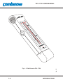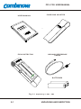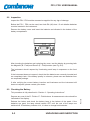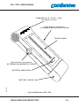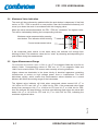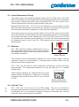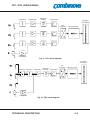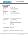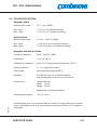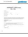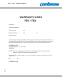
1
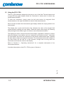
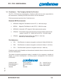
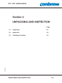
FD1 / FD2 USER MANUAL
FIELD DETECTOR
FD1 / FD2
User Manual
The Field Detector 1 and Field Detector 2 are professional handheld instruments to
measure extremely low frequency (FD1) and very low frequency (FD2) magnetic and
electric fields.
Rev. 1B
To make best use of the instruments, we recommend that you read this manual
carefully.
FD1 / FD2 USER MANUAL
Rev. 1B
Blank page.
FD1 / FD2 USER MANUAL
CONTENTS
Section 1
1.1
1.2
1.3
1.4
1.5
1.6
Section 2
INTRODUCTION
About this Manual
Magnetic Fields in the Environment
Electric Fields in the Environment
The Instrument
Using the FD1 / FD2
Combinova - The Company Behind the Product
3.1
3.2
3.3
3.4
3.5
3.6
3.7
3.8
3-8
Section 4
Functional Description
Magnetic Field Measurement (3 and 1 axis)
Electric Field Measurement
Maximum Display Indication
Upper Measurement Range
Lower Measurement Range
Batteries
Indicator Test
3-2
3-3
3-5
3-7
3-7
3-8
3-8
- TECHNICAL DESCRIPTION
4-2
4-3
- SPECIFICATIONS
5.1 FD1 specifications
5.2 FD2 specifications
Rev. 1B
2-2
2-3
2-3
- OPERATING INSTRUCTIONS
4.1 Measurement Principle
4.2 Electronics
Section 5
1-2
1-3
1-4
1-6
1-7
1-8
- UNPACKING AND INSPECTION
2.1 Unpacking
2.2 Inspection
2.3 Checking the battery
Section 3
Page
WARRANTY FORM
CONTENTS
5-1
5-2
FD1 / FD2 USER MANUAL
Rev. 1B
Blank page.
CONTENTS
FD1 / FD2 USER MANUAL
Section 1
INTRODUCTION
Page
About this Manual
1-2
1.2
Magnetic Fields in the Environment
1-3
1.3
Electric Fields in the Environment
1-4
1.4
The Instrument
1-6
1.5
Using the FD1 / FD2
1-7
1.6
Combinova - The Company Behind the Product
1-8
Rev. 1B
1.1
INTRODUCTION
1-0
FD1 / FD2 USER MANUAL
Rev. 1B
Blank page.
1-1
INTRODUCTION
FD1 / FD2 USER MANUAL
This manual contains a combined description of the FD1 / FD2 instruments.
1.1 About this Manual
Thank you for choosing the Field Detector FD1 / FD2 !
The FD1 / FD2 is designed using a combination of traditional electronics and surface
mounting technology ensuring a long life and trouble free operation.
This manual is intentionally sectioned for two types of users, the advanced user who is
already familiar with the subject of field measurements, and beginners who have little
or no knowledge of magnetic and electric field measurements.
We recommend the following use of this manual:
Experienced users:
Read this manual beginning with “Section 2 - Unpacking and inspection” continuing
with “Section 3 - Operating instructions” that will give you consise instructions for using
the instrument.
This will get you started measuring with the FD1 / FD2 in the shortest time.
When you are familiar with the instruments you might want to move on to “Section 4 Technical Description” together with “Section 5 - Specifications” to get a feel for of the
technical capabilities of the instrument.
New users:
Begin with “Section 1 - Introduction” that will give an introduction to the subject of field
measurements together with a brief introduction of the FD1 / FD2 and its use.
Rev. 1B
Move on to “Section 2 - Unpacking and inspection” continuing with “Section 3 Operating instructions” that will give you consise instructions for using the instrument.
INTRODUCTION
1-2
FD1 / FD2 USER MANUAL
1.2 Magnetic Fields in the Environment
Increasing use of electrical equipment has resulted in increased exposure to low
frequency magnetic and electric fields. In recent years this has led to concern that a
health hazard could arise from these low frequency fields.
Strong magnetic fields can also cause electrical interference problems, for example
disturbance of CRT type displays from external magnetic fields . The largest magnetic
fields are found around power transmission lines and power supply installations.
Electrical equipment in the home and working environments generate comparatively
strong magnetic fields.
The presence of such magnetic fields in the environment is beginning to cause
concern, and has led to demands for action to decrease these fields. This has led to
the development of the FD1 witch can be used to easily and quickly identify the source
of magnetic fields so that appropriate action can be taken.
Magnetic flux is measured in Tesla or in some countries in Gauss. In this manual we
will use Tesla. The conversion factor is 10 mG = 1 mT.
Magnetic fields from power lines are directly related to the phase current. Seasonal
and daily variations are caused by different power consumption demands. Close to the
power line the magnetic flux can reach a maximum of 10 - 30 mT, but decreases to
less than 1 mT at distances of 50 to 200 meters.
Magnetic fields at home and in our working environment are caused both by internal
and external sources. Typical external sources are power line and power distribution
substations close to buildings, while even water pipes, when carrying unbalanced
neutral currents create significant magnetic fields. Internal sources are a large variety
of electrical equipment and installation wiring.
Rev. 1B
The usual electrical equipment found at home or in the office generates magnetic
fields with dipole characteristics. The field strength decreases rapidly with distance.
Close to the source the field strength can be as high as 10 mT, but this decreases to a
background level at only one meters distance. In general the background magnetic
fields should be less than 0.1 mT, but in certain cases it can be as large as 1 - 3 mT.
1-3
INTRODUCTION
FD1 / FD2 USER MANUAL
1.3 Electric Fields in the Environment
Electric fields are present almost everywhere in connection to our use of alternating
electric power.
The electric fields in our environment and the problems they can cause has led to
increasing demands to examine and reduce them to minimize our daily exposure. This
concern is the background for the development of FD1 and FD2 as tools to identify
and measure different alternating electric field sources. The instruments can also be
used to verify that measures to reduce the fields are effectively implemented.
The strongest electric fields in our environment comes from high voltage power lines.
Other sources are found close to electrical equipment and appliances both at home
and in our work place.
The electric field strength from a power line is directly proportional to the applied
voltage. The electric field strength decreases with distance and are effectively reduced
if conductive objects are situated in between the power line and the measurement
position. Indoors the electric field from an outside power line is normally reduced to
very low levels by the walls and roof of the building.
The electric field directly underneath a high voltage power line can be between 3 10 kV/m. The electric field at distances between 50 to 200 meters is reduced to
around 100 V/m.
Normal electric appliances will cause electric fields unless they have a conductive
enclosure connected to protective ground in the power outlet. The electric field close
to appliances with non conductive enclosures could be 100 - 200 V/m and at distances
of 2 - 3 meters it has decreased to 10 - 30 V/m. Due to the amount of different
appliances and wiring we have at home and in offices, the background electric field is
very often around 20 - 30 V/m.
Rev. 1B
In most cases it is rather simple to reduce the electric fields to very low levels by using
wiring with a conductive screen and using grounded equipment with conductive
enclosures.
INTRODUCTION
1-4
FD1 / FD2 USER MANUAL
1-5
Rev. 1B
Fig. 1.1 Field Detector FD1 / FD2
INTRODUCTION
FD1 / FD2 USER MANUAL
1.4 The instrument (Fig. 1.1)
The FD1 / FD2 is a compact, portable, handheld and environmentally protected
instrument for measuring low frequency magnetic and electric fields. For field
detection and measurements it offers the following features:
•
Orthogonal coils, which means that magnetic fields are measured
independent of field direction.
•
A frequency range for FD1 of 20 Hz to 2000 Hz for extremely low frequency
magnetic and electric fields.
•
A frequency range for FD2 of 2 kHz to 400 kHz for very low frequency
magnetic and electric fields.
•
A wide dynamic range for FD1 of 40 nT to 100 mT for magnetic fields and
4 V/m to 10 kV/m for electric fields. A wide dynamic range for FD2 of 4 nT to
10 mT for magnetic fields and 0.4 V/m to 1000 V/m for electric fields.
•
True RMS measurements.
•
Large, easy to read, LED bar graph display
For the operator in the field, the designed portability of the FD1 / FD2 means that the
instrument is entirely self contained. These features are:
•
Powered by two R6 (AA) size 1.5 volt batteries.
•
A soft leather holster for safe carrying of the instrument.
•
A cable for making earth referenced measurements of electrical fields.
The instruments has features, despitem its compactness, that are made possible by
use of surface mounted electronics together with highly optimized mathematics in the
micro computer.
Rev. 1B
In short, the instrument should provide years of trouble free operation.
INTRODUCTION
1-6
FD1 / FD2 USER MANUAL
1.5 Using the FD1 / FD2.
The FD1 / FD2 has been designed to be easy to use in the field. The two buttons and
a large LED bar graph display allows the instrument to easily used in almost any
measurement situation.
To start the instrument, simply press the left side button for magnetic field
measurements or the right side button for electric field measurements.
Move around and watch the thermometer type display indicate the varying fields in the
environment.
The display has a peak hold function that indicates the value of the largest field
measured after pressing the start button. Reset the peak value simply by releasing
and pressing the start button again to initiate a new measurement session.
The display also has a value hold function that makes it possible to measure in places
where the display is not visible, such as “overhead” and “behind corners”. Just press
the start button and move the instrument to the desired measurement spot. Release
the start button without moving the instrument. The measured result at the release of
the start button will be held for a few seconds, enough time to bring back the
instrument and check the value on the display.
Refer to “Section 3 - Operating instructions” for a complete description of the
instruments features.
Rev. 1B
A technical description of the FD1 / FD2 is given in Section 4.
1-7
INTRODUCTION
FD1 / FD2 USER MANUAL
1.6 Combinova - The Company behind the Product
The FD1 / FD2 has been developed by Combinova AB, who are also responsible for
the manufacture, marketing and after sales service of the instrument.
Field measurement products from Combinova are:
Standard MPR instruments
•
MFM1000 Magnetic Field Meter for the VLF (2 - 400 kHz) range
•
MFM10
•
MFM1020 Automatic VDT magnetic field measurement system
•
EFM 200
Electrostatic fields and alternating electrical fields measurement
system in the ELF (5 - 2000 Hz) and VLF (2 - 400 kHz) range
•
EFM100
Alternating electric fields in the ELF (5 - 2000 Hz)
and VLF (2 - 400 kHz) ranges
Magnetic Field Meter for the ELF (5 - 2000 Hz) range
Field detectors
•
FD1
Field Detector to measure magnetic and electric fields (20-2000 Hz)
•
FD2
Field Detector to measure magnetic and electric fields (2 - 400 kHz)
•
FD 3
Field Dosimeter System for magnetic fields (20 - 2000 Hz)
Combinova works with Swedish and international industrial clients in the area of broad
technical development.
The depth of technical experience makes it possible for the company to handle all
stages of product development, including project management and technical
coordination.
Visiting address:
Domkraftsvägen 1
Bro
Sweden
Tel: +46 8 627 93 10
Fax: +46 8 29 59 85
www.combinova.se
Rev. 1B
Combinova AB
Domkraftsvägen 1
S 197 40 Bro
Sweden
INTRODUCTION
1-8
FD1 / FD2 USER MANUAL
Rev. 1B
Blank page.
1-9
INTRODUCTION
FD1 / FD2 USER MANUAL
Section 2
UNPACKING AND INSPECTION
Page
Unpacking
2-2
2.2
Inspection
2-3
2.3
Checking the battery
2-3
Rev.1B
2.1
UNPACKING AND INSPECTION
2-0
FD1 / FD2 USER MANUAL
USER MANUAL
FIELD DE TECTOR
CARRYING HOLSTER
GROUND REFERENCE
CABLE
BATTERIES
Fig. 2.1 U n p a c k i n g o f F D 1 / F D 2
2-1
UNPACKING AND INSPECTION
FD1 / FD2 USER MANUAL
The FD1 / FD2 is delivered in a cardboard box that should be saved if for any reason
the instrument needs to be returned to Combinova or its authorized dealer.
2.1 Unpacking
Inspect the box for any apparent damage caused by transportation handling. If
damage has occurred to the box or its contents, please contact the shipping company
that delivered your instrument.
The box should contain the following items (see Fig. 2.1):
Supplied items
•
FD1 / FD2 Instrument
•
Ground Reference Cable
•
Carrying Holster
•
Batteries
•
Operator’s Manual
If any item is missing, please contact your dealer.
Important! Complete the warranty form and return a copy to Combinova. The
warranty is only valid when the warranty form has been completed and received by
Combinova .
Rev.1B
Before using the instrument, read this manual carefully as described in “Section 1.1 About This Manual”.
UNPACKING AND INSPECTION
2-2
FD1 / FD2 USER MANUAL
2.2 Inspection
Inspect the FD1 / FD2 and the accessories supplied for any sign of damage.
Before the FD1 / FD2 can be used, two fresh R6 (AA) size 1.5 volt alkaline batteries
must be inserted in the instrument.
Remove the battery cover and insert the batteries as indicated in the bottom of the
battery compartment.
After inserting the batteries and replacing the cover, test the display by pressing both
the Magnetic (B - Field) and Electric (E - Field) buttons (see Fig. 2.2).
The instrument should respond by illuminating each lamp in sequence on the front
panel.
If the instrument does not respond, check that the batteries are correctly inserted and
are completely fresh. If the battery quality is unknown, please use new batteries from
an unopened package.
If after verifying the correct battery insertion and freshness and the instrument still
does not respond, please contact your dealer.
2.3 Checking the Battery
This procedure is fully described in “Section 3 - Operating Instructions”.
Release the button and check the battery lamp in the bottom of the panel. If the
batteries are good, the lamp should remain OFF until the rest of the lamps are
switched off. If the battery indicator is lit, it is time to change both batteries.
2-3
UNPACKING AND INSPECTION
Rev.1B
Depress any one of the B - Field or E - Field buttons. A measurement value should be
indicated on the display.
FD1 / FD2 USER MANUAL
SENS ORS for B - a nd E - field
(inside the cover)
Push button to measur e
ALTERNATING ELECTRIC FIELDS
FRONT PANEL
Push button to measur e
ALTERNATING MAGNETIC FIELDS
BATTERY INDICATOR
Rev.1B
BATTERY COVER
Fig. 2.2 Field Detector FD1 / FD2
UNPACKING AND INSPECTION
2-4
FD1 / FD2 USER MANUAL
Rev.1B
Blank page.
2-5
UNPACKING AND INSPECTION
FD1 / FD2 USER MANUAL
Section 3
OPERATING INSTRUCTIONS
Page
Functional Description
3-2
3.2
Magnetic Field Measurement (3 and 1 axis)
3-3
3.3
Electric Field Measurement
3-5
3.4
Maximum Display Indication
3-7
3.5
Upper Measurement Range
3-7
3.6
Lower Measurement Range
3-8
3.7
Batteries
3-8
3.8
Indicator Test
3-8
Rev.1B
3.1
OPERATING INSTRUCTIONS
3-0
FD1 / FD2 USER MANUAL
Rev.1B
Blank page.
3-1
OPERATING INSTRUCTIONS
FD1 / FD2 USER MANUAL
3.1 Functional Description
FD1 / FD2 is intended for use in measurement of alternating electrical and magnetic
fields emitted by electrical installations and all types of electronic equipment.
FD1 measures in the ELF (Extremely Low Frequency) range, which is 20 - 2000 Hz
and FD2 measures in the VLF (Very Low Frequency) range, Which is 2 - 400 kHz.
Visual display terminals (VDT’s) can be measured according to MPR 1990. In band I
using the FD1 and in band II using the FD2.
Z-axis
Measurement directions
Y-axis
X-axis
Magnetic field is normally
measured using three axis
(X,Y,Z)
Electric field is measured in
the forward di rection (Z).
Push button for e lectri c field
Measur ing mode
indicators
Thermometer type displa y
Push button for ma gnetic fiel d
Rev.1B
Battery indicator
Figure 3. 1 FD1 / FD2 - wi th controls, i ndicators and antenna or ientations
OPERATING INSTRUCTIONS
3-2
FD1 / FD2 USER MANUAL
3.2 Magnetic Field Measurement
FD1 / FD2 measures magnetic fields using three coils in orthogonal directions. This
means that the measurement result is independent of the instrument orientation. For
correct measurement distance keep in mind that the antenna centers are situated in
the cylindrical front part of the instrument.
With FD1 / FD2 in the desired position, depress and hold the left side push button.The
B indicator is lit and a few seconds later the display will show the current magnetic
field.
B - Field indicator is lit during
magnetic field measurements.
The indicator that is lit corresponds to a magnetic field of
400 nT.
The B - scale on the left has a
range from 40 nT to 100 mT for
FD1 and from 4 nT to 10 mT for
FD2.
Two adjacent indicators are lit if
the magnetic field is in between
the values on the scale. The example shows a value of 7 nT.
The button is released after the
measurement is completed. The displayed value is retained momentarily to enable
measurement in areas where the scale is not view able by the user. This feature is an
advantage when measuring high up, low down, behind or under fixed objects.
After release of the push button, FD1 / FD2 switches off automatically after about
2 seconds.
Rev.1B
A correction factor of two times (2x) the indicated display value is required when measuring railways with a 16 2/3 Hz electrical supply. This is due to the frequency characteristic curve of FD1.
3-3
OPERATING INSTRUCTIONS
FD1 / FD2 USER MANUAL
Measurement of magnetic field direction (1 - axis measurement)
The direction of the magnetic field is normally not of interest. FD1 / FD2 has a 3 - axis
design which means that FD1 / FD2 will always measure the correct magnetic field
value without the need for any special orientation of the instrument. This system is
called direction independent measurement.
Under certain circumstances it can be of interest to know the direction of the magnetic
field. For example, in technical development of a “low radiation product” or when field
reduction measures are planned.
To implement this, the FD1 / FD2 can be put into a 1 - axis measurement mode by
setting the change over switch hidden under the battery cover.
Remove the battery cover and change the switch, with a pencil or the contact pin on
the ground reference cable, through the small aperture in the upper side of the
instrument case. Set the switch to its right side position for 1 - axis measurements.
Switch located in this aperture.
Rev.1B
The B - indicator will blink in this measurement
modeand all measurement will only be made in the
Y - axis direction.
NOTE: Do not forget to return the switch to 3 - axis
normal mode after 1 - axis measurement.
OPERATING INSTRUCTIONS
3-4
FD1 / FD2 USER MANUAL
3.3 Electric Field Measurement
The position independent nature of magnetic field measurements is not valid when it
comes to measuring electric fields.
The electric field antenna is situated at the very top of the instrument and the
measurement direction is forwards. The instruments should be pointed at the object
you want to measure. To make accurate measurements, point the FD1 / FD2 towards
the field source and make sure that there is no obstructing object such as a person, a
hand or any other conductive object between the field source and the instrument
antenna.
Electric field measurements are made relative to some reference potential and this is
also true with FD1 / FD2.
An automatic connection to the user is made through the conductive push button
when the instrument is activated. The user thus becomes the reference potential for
electrical field measurements. This is equivalent to the situation of a person being
exposed to the measured field and is sufficient for most purposes.
See next part “Electrical field measurement with ground reference (external lead)” for
directions about making measurements with true ground reference.
With FD1 / FD2 in the desired position, depress and hold the right side push button
The indicator E is lit and a few seconds later the indicator on the display will show the
current electric field value.
E - Field indicator is lit during
electric field measurements.
The E - scale to the right has
a range from 4 V/m to
10 kV/m for FD1 and from
0.4 V/m to 1000 V/m for FD2.
Two adjacent indicators are lit if
the electric field is in between
the values on the scale. The
example shows a value of 0.7
V/m.
3-5
OPERATING INSTRUCTIONS
Rev.1B
The indicator that is lit
corresponds to an electric field
of 60 V/m.
FD1 / FD2 USER MANUAL
The push button is released after the measurement is completed. The displayed value
is retained momentarily to enable measurement in areas where the scale is not
viewable by the user. This feature is an advantage when measuring high up, low
down, behind or under fixed objects.
Releasing the button, FD1 / FD2 switches itself off automatically after 2 seconds.
Electrical field measurement with ground reference (external lead)
A ground reference lead can be connected to FD1 / FD2 if it is required to measure electrical
alternating fields under controlled conditions. A special lead (3 m long with a ground clip) is
supplied with the instrument. The instruments will then measure alternating electric fields with
a true ground reference.
The ground lead is connected to FD1 / FD2 by inserting the connecting plug through the hole
in the left side of the battery cover. The battery cover has no up or down side so if there is no
hole in the left side, remove the battery cover, turn it over to get the hole on the left side and
replace it.
The lead clip is then connected to a suitable ground (earth)
in the vicinity. For example, a metal connector on the rear
of a grounded electrical apparatus (computer etc.) or to
protective ground.
Ground cable connection point.
Rev.1B
WARNING !
Be careful when the ground reference cable is connected.
If the ground cli p touches the li ve termi nal, the
instrument wil l be connecte d to the power volta ge,
with consequential risks for personal injuries.
OPERATING INSTRUCTIONS
3-6
FD1 / FD2 USER MANUAL
3.4 Maximum Value Indication
The scale will be continuously updated whilst the push button is depressed. If the field
varies, or FD1 / FD2 is moved to a new position, then the illuminated indicator(s) will
move up or down the scale in accordance with the changing value.
When the value moves downwards, the FD1 / FD2 will “remember” the highest value.
This will be indicated by blinking the corresponding indicator.
Maximum value measured after pressing
start button. This indicator will be blinking.
Current measurement value.
If the measured value returns to the same value, the indicator will change from
blinking to fixed. The maximum value can be “reset” by releasing and depressing the
push button during the measurement.
3.5 Upper Measurement Range
The maximum measurement values of FD1 are 100 mT for magnetic fields and 10 kV/m for
electric fields. Corresponding values of FD2 are 10 mT for magnetic fields and
1000 V/m for electric fields. This covers most normally occurring situations.
Higher values are obtainable in the close vicinity of electrical apparatus containing
transformers or motors or high voltage power lines or installations. The field
diminishes quickly, which means that measurement values obtained at a normal
distance fall within the working range of the instruments.
Rev.1B
The highest value indicator will blink when measured values exceed 105 mT or
10.5 kV/m for FD1 and 10.5 mT or 1050 V/m for FD2. If the measured value drops
slowly from overage to 100 mT or 10 kV/m for FD1 and 10 mT or 1000 V/m for FD2,
then the indicator will stop blinking, and then start blinking again when the value falls
below 100 mT or 10 kV/m for FD1 and 10 mT or 1000 V/m for FD2, indicating the
maximum registered value.
3-7
OPERATING INSTRUCTIONS
FD1 / FD2 USER MANUAL
3.6 Lower Measurement Range
The lowest value on the scale for magnetic fields is 40 nT for FD1 and 4 nT for FD2,
which is indicated by a fixed display from the corresponding indicator. The instruments
can, however. indicate even lower values. Values below 25 nT for FD1 and 2.5 nT for
FD2 are indicated with a blinking lowest indicator on the scale.
Magnetic fields around 25 - 40 nT are to be considered as very low values in normal
work and home environments. Such values are normally only obtained far away from
electrical power distribution installations or other electrical equipment.
The lowest value on the scale for electric fields is 4 V/m for FD1 and 0.4 V/m for FD2,
which is indicated by a fixed display from the corresponding indicator. The instruments
can indicate even lower values. Values below 2.5 V/m for FD1 and 0.25 V/m for FD2
are indicated with a blinking lowest indicator on the scale. This can be demonstrated
by holding the hand in front of the FD1 / FD2 antenna, which screens the external
electrical field.
3.7 Batteries
FD1 / FD2 checks the battery voltage whilst in use. If
the voltage falls below a limit of 2.1 V, then the battery
warning indicator will flash after measurement when the
push button is released.
Battery indicator
This indicator and the measurement indicator (B or E) will flash together until the
instrument switches off automatically. A blinking battery indicator shows that the
batteries need to be changed soon.
FD1 / FD2 can be used for some additional time without risking inaccurate
measurements. The recommended batteries are two R6 (AA) size 1.5 V alkaline
standard cells.
Check that the batteries are replaced with the correct
polarity. Battery life depend on usage, but it is normally
estimated to be around 30 hours for FD1 and 10 hours
for FD2.
Battery compartment
with polarity indications
Rev.1B
3.8 Indicator Test
FD1 / FD2 has a test facility for the LED display. The test is activated by
simultaneously depressing and holding down both the B - and E - field push buttons.
All indicators are lit in a continuous sequence during this verification test. The test
continues until the push buttons are released.
OPERATING INSTRUCTIONS
3-8
FD1 / FD2 USER MANUAL
Rev.1B
Blank page.
3-9
OPERATING INSTRUCTIONS
FD1 / FD2 USER MANUAL
Section 4
TECHNICAL DESCRIPTION
Page
Measurement Principle
4-2
4.2
Electronics
4-3
Rev. 1B
4.1
TECHNICAL DESCRIPTION
4-0
FD1 / FD2 USER MANUAL
Rev. 1B
Blank page.
4-1
TECHNICAL DESCRIPTION
FD1 / FD2 USER MANUAL
4.1 Measurement Principle
FD1 / FD2 uses true RMS measurements of both magnetic and electric fields.
Measurements are made by a sampling technique with multiple samples to give a
complete representation of the signal. The sampled measurement values are
A/D converted and the microprocessor calculates the true RMS value.
Magnetic field measurements are made using three orthogonal coils and with normal
measurements the microprocessor calculates a direction independent measurement
result (three axis measurement).
The frequency response of the amplifiers in FD1 are adapted to avoid any influence
from movement of the instrument in the earth static magnetic field. The amplifiers
have a six pole high pass filter with a cut off frequency of 20 Hz. The normal
frequencies of sources for ELF measurements are either power frequencies
(50/60 Hz) or vertical deflection frequencies from VDTs (50 - 125 Hz). The modified
frequency response will cause no problems for these applications.
The frequency response will cause an attenuation of the signal for measurement
situations where the frequency of the source is substantially lower than 50 Hz. For
railway supply of 16.7 Hz basic frequency, the measurement values are attenuated to
around 50 % and results should be multiplied by 2.
The magnetic field measurement coils are significantly smaller than the ones defined
for VDT measurements by different standards. In a homogeneous field this has no
influence on the measurement result. In a very unhomogeneous field close to
appliances and VDTs there could be small differences. At normal distances from a
VDT the instruments will show a result that can be up to 2 - 3 % lower than of an
instrument with the standardized coil size.
Rev. 1B
The sensor for electric fields is significantly smaller than the standardized 300 mm
disc used in larger instruments. In the FD1 / FD2 the effect of this difference in sensor
size is compensated, as far as possible, to give the same readings as the
standardized instruments at normal measurement distances from the field source. In
cases close to a very wide spread source the FD1 / FD2 will give elevated results,
compared to a standardized instrument, caused by the smaller size of the sensor.
TECHNICAL DESCRIPTION
4-2
FD1 / FD2 USER MANUAL
4.2 Electronics
The electronics in the FD1 / FD2 are divided into analog and digital parts. The analog
parts carry out the measurements while the digital parts carry out the control of
instrument functions, battery monitoring and display control. Figure 4.1 shows the
block diagrams of FD1 and figure 4.2 shows the block diagrams of FD2.
The analog parts of the FD1 / FD2 have the following main functions:
•
Integrator stages.
•
FD1 has three-pole low-pass filters with a cut-off frequency of 2000 Hz.
•
FD2 has three-pole low-pass filters with a cut-off frequency of 400 kHz.
•
FD1 has six-pole high-pass filters with a cut-off frequency of 20 Hz.
•
FD2 has six-pole high-pass filters with a cut-off frequency of 2 kHz.
•
Full - wave rectifiers.
•
Linear to logarithmic converters.
•
A power supply for converting the 3 volt battery voltage to the 5 volts
required by the electronics.
The digital parts of the FD1 / FD2 have the following main functions:
A Motorola 68HC11 micro processor with an on chip A/D converter.
•
An 8 kbytes EEPROM memory for storage of software and correction
factors.This enables the instrument to have software updates “on site”
without having to replace sensitive electronic components.
•
A multiplexer driven 32 LED display.
•
Battery voltage monitor.
•
Operator controls.
Rev. 1B
•
4-3
TECHNICAL DESCRIPTION
FD1 / FD2 USER MANUAL
Integration
Bandpass
filtering
Amplification
Compression
Bargraph
LED display
A/D
conversion
Microprocessor
Preamplifier
Fig. 4.1 FD1 block diagram
Bargraph
LED display
Bandpass
Multiplexer Integration Amplification filtering Compression
A/D
conversion
Microprocessor
Preamplifier
Fig. 4.2 FD2 block diagram
TECHNICAL DESCRIPTION
4-4
FD1 / FD2 USER MANUAL
Rev. 1B
Blank page.
4-5
TECHNICAL DESCRIPTION
FD1 / FD2 USER MANUAL
Section 5
SPECIFICATIONS
Page
FD1 specification
5-1
5.2
FD2 specification
5-2
Rev. 1B
5.1
SPECIFICATIONS
5-0
FD1 / FD2 USER MANUAL
5.1 FD1 SPECIFICATIONS
Magnetic fields
Measurement range:
40 nT - 100 mT (RMS)
Min. value:
Max. value:
< 25 nT (40 nT indicator blinking)
> 105 mT (100 mT indicator blinking)
Electric fields
Measurement range:
4 V/m - 10 kV/m (RMS)
Min. value:
Max. value:
< 2.5 V/m (4 V/m indicator blinking)
> 10.5 kV/m (10 kV/m indicator blinking)
Magnetic and Electric fields
Frequency response:
20 Hz - 2000 Hz (-3dB)
Uncertainty:
±5% (18 - 28°C)
Temperature coefficient:
max. 1%/°C (at temperatures outside 18 - 28°C)
Display resolution:
4 - 12 % (logarithmic scale)
Display type:
32 light emitting diodes (LED:s)
Batteries:
Two R6 (AA) size 1.5 V alkaline batteries
with operating time of 30 hours in normal use.
Dimensions:
Length: 205 mm
Width: 70 mm
Height: 35 mm
Weight: 290 g (including batteries)
-10°C to + 40°C
Individual data given in the technical data are subject to change without prior written
notice. Specifications are given at the ambient temperature Tamb = 23 ± 5 degrees
centigrade.
5-1
SPECIFICATIONS
Rev. 1B
Operating temperature
FD1 / FD2 USER MANUAL
5.2 FD2 SPECIFICATIONS
Magnetic fields
Measurement range:
4 nT - 10 mT (RMS)
Min. value:
Max. value:
< 2.5 nT (4 nT indicator blinking)
> 10.5 mT (10 mT indicator blinking)
Electric fields
Measurement range:
0.4 V/m - 1000 V/m (RMS)
Min. value:
Max. value:
< 0.25 V/m (0.4 V/m indicator blinking)
> 1050 V/m (1000 V/m indicator blinking)
Magnetic and Electric fields
Frequency response:
2 kHz - 400 kHz (-3dB)
Uncertainty:
±5% (18 - 28°C)
Temperature coefficient:
max. 1%/C (at temperatures outside 18 - 28 °C)
Display resolution:
4 - 12 % (logarithmic scale)
Display type:
32 light emitting diodes (LED:s)
Batteries:
Two R6 (AA) size 1.5 V alkaline batteries
with operating time of 10 hours in normal use.
Dimensions:
Length: 205 mm
Width: 70 mm
Height: 35 mm
Weight: 290 g (including batteries)
Rev. 1B
Operating temperature
-10°C to +40°C
Individual data given in the technical data are subject to change without prior written
notice. Specifications are given at the ambient temperature Tamb = 23 ± 5 degrees
centigrade.
SPECIFICATIONS
5-2
FD1 / FD2 USER MANUAL
Rev. 1B
Blank page.
5-3
SPECIFICATIONS
FD1 / FD2 USER MANUAL
WARRANTY CARD (copy)
FD1 / FD2
Customer:
Customer address:
Delivery date:
/
Warranty period
:
20
/
20
-
/
20
Serial number:
The warranty includes material and labor costs for service and repair. A condition for
the warranty to be valid is that a correctly filled in copy of the warranty form is sent to
Combinova Marketing AB. If service is required the instrument should be sent to:
COMBINOVA AB
Domkraftsvägen 1 S 197 40 Bro
SWEDEN
NOTE! On return shipping documents it must be stated that the instrument is of
Swedish origin and returned for repair/service.
Cost for freight, customs duty etc. are not included in warranty and will be invoiced
separately.
Bro
/
20
Rev. 1B
COMBINOVA AB
FD1 / FD2 USER MANUAL
Rev. 1B
Blank page.
FD1 / FD2 USER MANUAL
WARRANTY CARD
FD1 / FD2
Customer:
Customer address:
Delivery date:
/
20
Warranty period:
/
20
-
/
20
Serial number:
The warranty includes material and labor costs for service and repair. A condition for
the warranty to be valid is that a correctly filled in copy of the warranty form is sent to
Combinova Marketing AB. If service is required the instrument should be sent to:
COMBINOVA AB
Domkraftsvägen 1 S-197 40 Bro
SWEDEN
NOTE! On return shipping documents it must be stated that the instrument is of
Swedish origin and returned for repair/service.
Cost for freight, customs duty etc. are not included in warranty and will be invoiced
separately.
Bro
/
20
Rev. 1B
COMBINOVA AB
FD1 / FD2 USER MANUAL
Rev. 1B
Blank page.