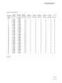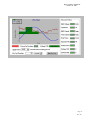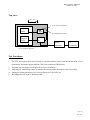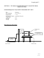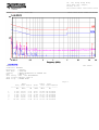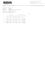
1
Report Number: 02E0552-E
October 30, 2002
EMC COMPLIANCE TEST REPORT
for
USB HUB
Trade Name
Model Number
Serial Number
Report Number
Date
Regulations
:
:
:
:
:
:
OMEGA
UHB-114
N/A
02E0552-E
October 30, 2002
See below
Standards
EN 55022: 1998
EN 61000-3-2: 1995+A1: 1998+A2: 1998+A14: 2000
EN 61000-3-3: 1995
EN 55024: 1998
- IEC 61000-4-2: 1995 +A2: 2001
- IEC 61000-4-3: 1995
- IEC 61000-4-4: 1995
- IEC 61000-4-5: 1995
- IEC 61000-4-6: 1996
- IEC 61000-4-8: 1993
- IEC 61000-4-11: 1994
Results (Pass/Fail)
PASS
PASS
PASS
PASS
PASS
PASS
PASS
PASS
PASS
N/A
PASS
Prepared for:
OMEGA TECHNOLOGY OF TAIWAN INC.
6F, NO. 87, Sec. 3, Chung-Yang Rd., Tu-Cheng,
Taipei, Taiwan, R. O. C.
Prepared by:
C&C LABORATORY CO., LTD.
#B1, 1st Fl., Universal Center, No. 183, Sec. 1,
Tatung Rd., Hsi Chin,
Taipei Hsien, Taiwan, R.O.C.
TEL: (02)86422071 / FAX: (02)86422256
This report shall not be reproduced, except in full, without the written approval of
C&C Laboratory Co., Ltd.
Page 1 of 68
Rev. 00
Report Number: 02E0552-E
October 30, 2002
EC-Declaration of Conformity
For the following equipment:
USB HUB
( Product Name )
UHB-114 / OMEGA
( Model Designation / Trade name )
OMEGA TECHNOLOGY OF TAIWAN INC.
( Manufacturer Name )
6F, NO. 87, Sec. 3, Chung-Yang Rd., Tu-Cheng, Taipei, Taiwan, R. O. C.
(Manufacturer Address)
is herewith confirmed to comply with the requirements set out in the Council Directive on the
Approximation of the Laws of the Member States relating to Electromagnetic Compatibility Directive
(89/336/EEC, Amended by 92/31/EEC, 93/68/EEC & 98/13/EC), For the evaluation regarding the
Electromagnetic Compatibility (89/336/EEC, Amended by 92/31/EEC & 93/68/EEC & 98/13/EC ) the
following standards are applied:
V EN 55022: 1998
V EN 61000-3-2: 1995+A1: 1998+A2: 1998+A14: 2000
V EN 61000-3-3: 1995
V EN55024: 1998
IEC 61000-4-2: 1995 +A2: 2001, IEC 61000-4-3: 1995, IEC 61000-4-4: 1995
IEC 61000-4-5: 1995, IEC 61000-4-6: 1996, IEC 61000-4-11: 1994
The following manufacturer / importer or authorized representative established within the EUT is
responsible for this declaration:
( Company Name )
( Company Address )
Person responsible for making this declaration:
( Name, Surname )
( Position / Title )
( Place )
( Date )
( Legal Signature )
Page 2
Rev. 00
Report Number: 02E0552-E
October 30, 2002
TABLE OF CONTENTS
DESCRIPTION
PAGE
VERIFICATION OF COMPLIANCE
5
GENERAL INFORMATION
6
SYSTEM DESCRIPTION
7
PRODUCT INFORMATION
8
SUPPORT EQUIPMENT
9
TEST FACILITY
10
TEST EQUIPMENT
SECTION 1 EN 55022(LINE CONDUCTED & RADIATED
EMISSION)
11
14
MEASUREMENT PROCEDURE & LIMIT (LINE CONDUCTED
EMISSION TEST)
MEASUREMENT PROCEDURE & LIMIT (RADIATED EMISSION
TEST)
14
BLOCK DIAGRAM OF TEST SETUP
19
SUMMARY DATA
SECTION 2 EN61000-3-2 & EN 61000-3-3 (POWER HARMONICS
20
17
22
& VOLTAGE FLUCTUATION/FLICKER)
BLOCK DIAGRAM OF TEST SETUP
22
RESULT
22
SECTION 3 IEC 61000-4-2 (ELECTROSTATIC DISCHARGE)
33
BLOCK DIAGRAM OF TEST SETUP
33
TEST PROCEDURE
34
PERFORMANCE & RESULT
34
SECTION 4 IEC 61000-4-3 (RADIATED ELECTROM
38
AGNETIC FIELD)
BLOCK DIAGRAM OF TEST SETUP
38
TEST PROCEDURE
39
PERFORMANCE & RESULT
40
Page 3
Rev. 00
Report Number: 02E0552-E
October 30, 2002
DESCRIPTION
SECTION 5
IEC 61000-4-4 (FAST TRANSIENTS/BURST)
PAGE
41
BLOCK DIAGRAM OF TEST SETUP
41
TEST PROCEDURE
42
PERFORMANCE & RESULT
SECTION 6 IEC 61000-4-5 (SURGE IMMUNITY)
42
BLOCK DIAGRAM OF TEST SETUP
43
TEST PROCEDURE
44
PERFORMANCE & RESULT
SECTION 7 IEC 61000-4-6 (CONDUCTED DISTURBANCE,
INDUCED BY RADIO-FREQUENCY FIELDS)
44
BLOCK DIAGRAM OF TEST SETUP
45
TEST PROCEDURE
46
PERFORMANCE & RESULT
SECTION 8 IEC 61000-4-8 (Power Frequency Magnetic Field))
47
BLOCK DIAGRAM OF TEST SETUP
48
TEST PROCEDURE
49
PERFORMANCE & RESULT
SECTION 9 IEC 61000-4-11 (VOLTAGE DIP/INTERRUPTION)
49
BLOCK DIAGRAM OF TEST SETUP
50
TEST PROCEDURE
51
PERFORMANCE & RESULT
51
APPENDIX 1 PHOTOGRAPHS OF TEST SETUP
EN 55022 TEST
EN 61000-3-2 TEST
EN 61000-3-3 TEST
IEC 61000-4-2 TEST
IEC 61000-4-3 TEST
IEC 61000-4-4 TEST
IEC 61000-4-5 TEST
IEC 61000-4-6 TEST
IEC 61000-4-11 TEST
52
APPENDIX 2 PHOTOGRAPHS OF EUT
62
APPENDIX 3
68
CONDUCTED EMISSION PLOT & RADIATED
43
45
48
50
EMISSION DATA
Page 4
Rev. 00
Report Number: 02E0552-E
October 30, 2002
VERIFICATION OF COMPLIANCE
Equipment Under Test:
USB HUB
Trade Name:
OMEGA
Model Number:
UHB-114
Serial Number:
N/A
Applicant:
OMEGA TECHNOLOGY OF TAIWAN INC.
6F, NO. 87, Sec. 3, Chung-Yang Rd., Tu-Cheng,
Taipei, Taiwan, R. O. C.
Manufacturer:
OMEGA TECHNOLOGY OF TAIWAN INC.
6F, NO. 87, Sec. 3, Chung-Yang Rd., Tu-Cheng,
Taipei, Taiwan, R. O. C.
Type of Test:
EMC Directive 89/336/EEC for CE Marking
Technical Standards:
EN 55022: 1998
EN 61000-3-2: 1995+A1: 1998+A2: 1998+A14: 2000
EN 61000-3-3: 1995
EN 55024: 1998
(IEC 61000-4-2: 1995 +A2: 2001, IEC 61000-4-3: 1995
IEC 61000-4-4: 1995, IEC 61000-4-5: 1995
IEC 61000-4-6: 1996, IEC 61000-4-11: 1994)
File Number:
02E0552-E
Date of test:
October 29, 2002 & October 30, 2002
Deviation:
N/A
Condition of Test Sample: Normal
The above equipment was tested by C&C Laboratory Co., Ltd. for compliance with the requirements
set forth in EMC Directive 89/336/EEC and the Technical Standards mentioned above. This said
equipment in the configuration described in this report shows the maximum emission levels emanating
from equipment and the level of the immunity endurance of the equipment are within the compliance
requirements.
The test results of this report relate only to the tested sample identified in this report.
Approved by Authorized Signatory:
James Chan / Manager
Page 5
Rev. 00
Report Number: 02E0552-E
October 30, 2002
GENERAL INFORMATION
Applicant:
OMEGA TECHNOLOGY OF TAIWAN INC.
6F, NO. 87, Sec. 3, Chung-Yang Rd., Tu-Cheng,
Taipei, Taiwan, R. O. C.
Contact Person:
Victor Kang / R&D Manager
Manufacturer:
OMEGA TECHNOLOGY OF TAIWAN INC.
6F, NO. 87, Sec. 3, Chung-Yang Rd., Tu-Cheng,
Taipei, Taiwan, R. O. C.
File Number:
02E0552-E
Date of Test:
October 29, 2002 & October 30, 2002
Equipment Under Test:
USB HUB
Trade Name:
OMEGA
Model Number:
UHB-114
Serial Number:
N/A
Type of Test:
EMC Directive 89/336/EEC for CE Marking
Technical Standards:
EN 55022: 1998
EN 61000-3-2: 1995+A1: 1998+A2: 1998+A14: 2000
EN 61000-3-3: 1995
EN 55024: 1998
(IEC 61000-4-2: 1995 +A2: 2001, IEC 61000-4-3: 1995
IEC 61000-4-4: 1995, IEC 61000-4-5: 1995
IEC 61000-4-6: 1996, IEC 61000-4-11: 1994)
Frequency Range
(EN 55022):
150kHz to 30MHz for Line Conducted Test
30MHz to 1000MHz for Radiated Emission Test
Test Site
C&C LABORATORY CO., LTD.
No. 199, Chung Sheng Road, Hsin Tien City, Taipei
Taiwan, R. O. C.
Page 6
Rev. 00
Report Number: 02E0552-E
October 30, 2002
SYSTEM DESCRIPTION
EUT Test Procedure:
1. Windows 2000 Boots System.
2. Run EMCTEST.exe To Activate All Peripherals And Display “H” Pattern On Monitor Screen.
Page 7
Rev. 00
Report Number: 02E0552-E
October 30, 2002
PRODUCT INFORMATION
Housing Type:
Plastic
EUT Power Rating:
DC 6V from AC Adaptor
AC power during Test:
230VAC, 50Hz to AC Adaptor
AC Adaptor Manufacturer:
OEM
AC Adaptor Model Number:
AD-062A1B
AC Power Cord Ty pe:
Unshielded, 1.8m (Detachable)
DC Power Cord Type:
Unshielded, 2.0m (Non-Detachable)
EUT I/O Cable Type:
Shielded, 1.6m (Detachable)
OSC/Clock Frequency:
12MHz
I/O Port of EUT:
I/O PORT TYPES
1). USB PORT (1.1)
Q’TY
TESTED WITH
5
5
Note: N/A
Page 8
Rev. 00
Report Number: 02E0552-E
October 30, 2002
SUPPORT EQUIPMENT
Host PC Devices:
No
1.
Equipment
HDD
Model
Serial
FCC/BSMI
#
#
ID
5T040H4
N/A
Trade Name
BSMI ID: 3892D143
DoC
BSMI ID: 3892B860
DoC
BSMI ID: 3892A885
Maxtor
2.
Power
ST-250BLV
N/A
3.
CD/R
CD-540E
4866830
4.
Floppy Disk
D353M3
N/A
62007003
MITSUMI
5.
CPU (2.0GHz)
P4
N/A
N/A
INTEL
6.
RAM(256MB)
RD256K33
220155
N/A
KINGMAX
7.
M/B
MS-6398
N/A
DoC
MSI
8.
VGA Card
V7100MAGIC/PU
19CK11266
RE/32M/SD/T
DoC
41017048
ASUS
No Equipment
1.
2.
3.
4.
5.
6.
USB
Mouse
USB
Mouse
USB
Mouse
USB
Mouse
PS/2
Keyboard
PS/2
Mouse
Model
Serial
FCC/ BSMI
#
#
ID
DoC
BSMI ID:3892A471
DoC
BSMI ID:3892A471
DoC
BSMI ID:42006012
DoC
BSMI ID:3892A471
Trade Name
M-BE58
LZE20302464
LOGITECH
M-BE58
LZE20302460
M-BE58
LZA10752403
M-BE58
LZE20302249
6311-TA
N/A
BSMI ID:3882A039 ACER
M-S34
LZC01169895
DZL211029
LOGITECH
BSMI ID:4862A011
LOGITECH
LOGITECH
LOGITECH
7.
Printer
EPSONSTYLU
DW4E126671
SC20SX
BSMI ID:3902E004 EPSON
8.
Monitor
1900FP
DoC
DELL
BSMI ID:3902C877
9.
Modem
5JEG4033MKO L0063CG2D007190 5RJTAI-35500-M 5-E
N/A
TOPSOLUTION
Seventeam
TEAC
Data
Cable
Power
Cord
Shielded,
1.9m
Shielded,
1.9m
Shielded,
1.8 m
Shielded,
1.9m
Shielded,
1.7m
Shielded,
1.9m
Shielded,
1.8 m
Shielded,
1.8m
with two cores
Shielded,
0.8 m
N/A
N/A
N/A
N/A
N/A
N/A
Unshielded,
1.8m
Unshielded,
1.8m
with a core
Unshielded,
1.8m
Note: All the above equipment/cables were placed in worse case positions to maximize emission
signals.
Grounding: Grounding was in accordance with the manufacturer’s requirements and conditions
for the intended use.
Page 9
Rev. 00
Report Number: 02E0552-E
October 30, 2002
TEST FACILITY
Location:
No. 199, Chung Sheng Road, Hsin Tien City,
Taipei, Taiwan, R. O. C.
Description:
There are two 3/10m open area test sites and one line conducted lab for
final test.
The Open Area Test Sites and the Line Conducted labs are constructed
and calibrated to meet the FCC requirements in documents ANSI C63.4:
1992 and CISPR 22/EN 55022 requirements.
Site Filing:
A site description is on file with the Federal Communications
Commission, 7435 Oakland Mills Road, Columbia, MD 21046.
Registration also was made with Voluntary Control Council for
Interference (VCCI).
Site Accreditation:
Accredited by A2LA (Certificate #: 824.01) for EMC.
Also accredited by BSMI for the product category of Information
Technology Equipment.
Instrument Tolerance:
All measuring equipment is in accord with ANSI C63.4 and CISPR 22
requirements that meet industry regulatory agency and accreditatio n
agency requirement.
Ground Plane:
Two conductive reference ground planes were used during the Line Conducted
Emission, one in vertical and the other in horizontal. The dimensions of these ground planes are as
below. The vertical ground plane was placed distancing 40 cm to the rear of the wooden test table on
where the EUT and the support equipment were placed during test. The horizontal ground plane
projected 50 cm beyond the footprint of the EUT system and distanced 80 cm to the wooden test table.
For Radiated Emission Test, one horizontal conductive ground plane extended at least 1m beyond the
periphery of the EUT and the largest measuring antenna, and covered the entire area between the EUT
and the antenna. It has no holes or gaps having longitudinal dimensions larger than one-tenth of a
wavelength at the highest frequency of measurement up to 1GHz.
Page 10
Rev. 00
Report Number: 02E0552-E
October 30, 2002
TEST EQUIPMENT LIST (EMISSION)
Instrumentation: The following list contains equipment used at C & C Laboratory Co., Ltd. for
testing. The equipment conforms to the CISPR 16-1 / ANSI C63.2-1988 Specifications for
Electromagnetic Interference and Field Strength Instrumentation from 9kHz to 1.0 / 2.0 GHz.
Equipment used during the tests:
Open Area Test Site:
EQUIPMENT
TYPE
EMC
ANALYZER
AMPLIFIER
#D
MFR
MODEL
NUMBER
SERIAL
NUMBER
LAST
CAL.
CAL.
DUE
HP
8595EM
3412A00104
03/01/02
02/28/03
HP
8447DB
1644A02328
05/05/02
05/04/03
ANTENNA
SCHWARZBECK
VULB 9160
3104
05/12/02
05/11/03
CABLE
BELDEN
9913
N-TYPE08
04/17/02
04/16/03
SERIAL
NUMBER
840455/006
LAST
CAL.
03/16/02
CAL.
DUE
03/15/03
Conducted Emission Test Site: Conducted Room
EQUIPMENT
TYPE
TEST
RECEIVER
LISN
MFR
R&S
MODEL
NUMBER
ESHS20
EMCO
3825/2
1842
01/11/02
01/10/03
LISN(EUT)
EMCO
3825/2
1435
01/16/02
01/15/03
The calibrations of the measuring instruments, including any accessories that may effect such
calibration, are checked frequently to assure their accuracy. Adjustments are made and correction
factors applied in accordance with instructions contained in the manual for the measuring instrument.
Page 11
Rev. 00
Report Number: 02E0552-E
October 30, 2002
TEST EQUIPMENT LIST
For Power Harmonic & Voltage Fluctuation/Flicker Measurement:
Manufacturer/Type
HP /
Harmonic & Flicker Tester
Model No.
Serial No.
Last Cal.
Cal. Due
6842A
3531A-000142
06/18/2002
06/17/2003
Model No.
Serial No.
Last Cal.
Cal. Due
NSG 432
2029
02/06/2002
02/05/2003
For ESD test:
Manufacturer/Type
Schaffner /
ESD Simulator
For Radiated Electromagnetic Field immunity Measurement:
Manufacturer/Type
R&S / Signal Generator
IFI /
“E” Field sensor/ Light
Modulator Transmitter
IFI / Combination Amplifier
Model No.
SMY 02
EFS-5
Serial No.
DE13751
713-0695
Last Cal.
01/10/2002
06/28/2002
Cal. Due
01/09/2003
06/27/2003
SMX100
2067-1196
IFI / Leveling Pre-Amplifier
LPA-5B
714-0695
EMCO / Biconilog Antenna
3142
9609-1087
No Calibration
Required
No Calibration
Required
No Calibration
Required
No Calibration
Required
No Calibration
Required
No Calibration
Required
Model No.
E421
Serial No.
9502326
Last Cal.
10/01/2002
Cal. Due
09/30/2003
CCL-4
9503290
No Calibration
Required
No Calibration
Required
Model No.
E501
Serial No.
9502324
Last Cal.
10/31/2002
Cal. Due
10/30/2003
CM-TELCD
0104399
No Calibration
Required
No Calibration
Required
CM-I/OCD
0103234
No Calibration
Required
No Calibration
Required
For Fast Transients/Burst test:
Manufacturer/Type
KeyTek Instruments /
EFT Generator
KeyTek Instruments /
Capacitive Clamp
For Surge Immunity test:
Manufacturer/Type
KeyTek Instruments/
Surger Generator
Telecom Lines Coupler
DECOUPLER
KeyTek Instruments
I/O Signal Line
DECOUPLER
KeyTek Instruments
Page 12
Rev. 00
Report Number: 02E0552-E
October 30, 2002
For CS test:
Manufacturer/Type
R&S / Signal Generator
IFI / Combination Amplifier
Model No.
SMY 02
SMX100
Serial No.
DE13751
2067-1196
99122
Last Cal.
01/10/2002
No Calibration
Required
No Calibration
Required
10/26/2002
Cal. Due
01/09/2003
No Calibration
Required
No Calibration
Required
10/25/2003
IFI / Leveling Pre-Amplifier
LPA-5B
714-0695
54
10/29/2002
10/28/2003
02541
No Calibration
Required
No Calibration
Required
Model No.
MAG 100.1
Serial No.
081436-02
CFC-105
810390
932C
2K0900285
Last Cal.
No Calibration
Required
No Calibration
Required
10/24/2002
Cal. Due
No Calibration
Required
No Calibration
Required
10/23/2003
FISCHER /
FCC-801-M3-16A
Power Line Coupling
Decoupling Network
FISCHER /
F-120-9B
Bulk Current Injection Probe
Narda /
769-6
High Power Attenuator
For Power Frequency Magnetic Field test :
Manufacturer/Type
Haefely /
Magic Field Tester
Extech Electronics /
Frequency Converter
CHY/
AC/DC Clamp Meter
For Voltage Dips/Short Interruption and Voltage Variation Immunity test:
Manufacturer/Type
Haefely /
Dips/Inerruption/Variations
Tester
FLUKE /
79 Series Ii Multimeter
Model No.
PLINE 1610
Serial No.
081568-06
Last Cal.
04/25/2002
Cal. Due
04/24/2003
79-II
66400868
07/02/2002
07/01/2003
Page 13
Rev. 00
Report Number: 02E0552-E
October 30, 2002
SECTION 1 EN 55022 (LINE CONDUCTED & RADIATED EMISSION)
MEASUREMENT PROCEDURE
(PRELIMINARY LINE CONDUCTED EMISSION TEST)
1) The equipment was set up as per the test configuration to simulate typical actual usage per the
user’s manual. When the EUT is a tabletop system, a wooden table with a height of 0.8 meters is
used and is placed on the ground plane as per EN 55022 (see Test Facility for the dimensions of
the ground plane used). When the EUT is a floor-standing equipment, it is placed on the
ground plane which has a 3-12 mm non-conductive covering to insulate the EUT from the ground
plane.
2) Support equipment, if needed, was placed as per EN 55022.
3) All I/O cables were positioned to simulate typical actual usage as per EN 55022.
4) The EUT received DC 6V power through AC Adaptor and Line Impedance Stabilization
Network (LISN) which supplied power source of 230VAC/ 50Hz and was grounded to the ground
plane.
5) All support equipment received power from a second LISN supplying power of 110VAC/60Hz, if
any.
6) The EUT test program was started. Emissions were measured on each current carrying line of
the EUT using a spectrum analyzer / Receiver connected to the LISN powering the EUT. The
LISN has two monitoring points: Line 1 (Hot Side) and Line 2 (Neutral Side). Two scans were
taken: one with Line 1 connected to Analyzer / Receiver and Line 2 connected to a 50 ohm load;
the second scan had Line 1 connected to a 50 ohm load and Line 2 connected to the Analyzer /
Receiver.
7) Analyzer / Receiver scanned from 150kHz to 30MHz for emissions in each of the test modes.
8) During the above scans, the emissions were maximized by cable manipulation.
9) The following test mode were scanned during the preliminary test:
Mode:
1
NORMAL MODE
10) After the preliminary scan, we found the following test mode producing the highest emission
level.
Mode:
1.
Then, the EUT configuration and cable configuration of the above highest emission level were
recorded for reference of final testing.
Page 14
Rev. 00
Report Number: 02E0552-E
October 30, 2002
MEASUREMENT PROCEDURE
(FINAL LINE CONDUCTED EMISSION TEST)
1) EUT and support equipment was set up on the test bench as per step 10 of the preliminary test.
2) A scan was taken on both power lines, Line 1 and Line 2, recording at least the six highest
emissions. Emission frequency and amplitude were recorded into a computer in which correction
factors were used to calculate the emission level and compare reading to the applicable limit. If
EUT emission level was less –2dB to the A.V. limit in Q.P. mode, then the emission signal was
re-checked using an A.V. detector.
3) The test data of the worst case condition(s) was reported on the Summary Data page.
Data Sample:
Meter
Freq
Reading
(MHz)
(dBuV)
x.xx
x.xx
C.F.
(dB)
x.xx
Corrected
Reading
(dBuV)
38.38
Limits
(dBuV)
56.00
Margin
(dB)
-17.62
Reading
Type
(P/Q/A)
P
Line
(L1/L2)
L1
C.F.(Correction Factor)=Insertion Loss + Cable Loss
Corrected Reading = Metering Reading + C.F.
Margin=Corrected Reading - Limits
P=Peak Reading
Q=Quasi-peak
A=Average Reading
L1=Hot
L2=Neutral
Comments: N/A
LINE CONDUCTED EMISSION LIMIT (EN 55022)
Frequency
150kHz-500kHz
500kHz-5MHz
5MHz-30MHz
Maximum RF Line Voltage
Q.P.
AVERAGE
66-56dBuV
56-46dBuV
56dBuV
46dBuV
60dBuV
50dBuV
Note: The lower limit shall apply at the transition frequency.
Page 15
Rev. 00
Report Number: 02E0552-E
October 30, 2002
MEASUREMENT PROCEDURE
(COMMON MODE CONDUCTED EMISSION MEASUREMENT)
1) Selecting ISN for unscreened cable or a current probe for screened cable to take measurement.
2) The port of the EUT was connected to the remote side support equipment through the ISN/Current
Probe and communication in normal condition.
3) Making a overall range scan by using the test receiver controlled by controller and record at least
six highest emissions for showing in the test report.
4) Emission frequency and amplitude were recorded into a computer in which correction factors were
used to calculate the emission level and compare reading to the applicable limit.
5) In case of measuring on the screened cable, the current limit shall be applied, otherwise the voltage
limit should be applied.
6) The following test mode(s) were scanned during the preliminary test:
Mode: N/A (EUT no any Telecommunicate Port)
7) After the preliminary scan, we found the following test mode(s) producing the highest emission
level and test date of the worst case was reported on the summary data page.
Mode: N/A
Data Sample:
Freq
Meter Reading
(MHz)
(dBuV)
x.xx
x.xx
C.F.
(dB)
x.xx
Corrected Reading
(dBuV)
59.26
Limits
(dBuV)
74.00
Margin
(dB)
-14.74
Reading Type
(P/Q/A)
P
C.F.(Correction Factor)=Insertion Loss (9.5dB) + Cable Loss
Corrected Reading = Metering Reading + C.F.
Margin=Corrected Reading - Limits
P=Peak Reading
Q=Quasi-peak
A=Average Reading
Comments: N/A
COMMON MODE CONDUCTED EMISSION LIMIT
AT TELECOMMUNICATION PORTS
CE-Mark ( EN 55022:1998 )
CLASS
B
Measuring
Band
150kHz-500kHz
500kHz-30MHz
Voltage limit dB(uV)
Q.P.
AV
84-74
74-64
74
64
Current limit dB(uA)
Q.P.
AV
40-30
30-20
30
20
Note: The lower limit shall apply at the transition frequency.
Page 16
Rev. 00
Report Number: 02E0552-E
October 30, 2002
MEASUREMENT PROCEDURE
(PRELIMINARY RADIATED EMISSION TEST)
1) The equipment was set up as per the test configuration to simulate typical actual usage per the
user’s manual. When the EUT is a tabletop system, a wooden turntable with a height of 0.8
meters is used which is placed on the ground plane as per EN 55022 (see Test Facility for the
dimensions of the ground plane used). When the EUT is a floor-standing equipment, it is placed
on the ground plane which has a 3-12 mm non-conductive covering to insulate the EUT from the
ground plane.
2) Support equipment, if needed, was placed as per EN 55022.
3) All I/O cables were positioned to simulate typical actual usage as per EN 55022.
4) The EUT received DC 6V power source from AC Adaptor (230VAC/50Hz) the outlet socket under
the turntable. All support equipment received 110VAC/60Hz power from another socket under the
turntable, if any.
5) The antenna was placed at 10 meter away from the EUT as stated in EN 55022. The antenna
connected to the analyzer via a cable and at times a pre-amplifier would be used.
6) The Analyzer / Receiver quickly scanned from 30MHz to 1000MHz. The EUT test program was
started. Emissions were scanned and measured rotating the EUT to 360 degrees and positioning
the antenna 1 to 4 meters above the ground plane, in both the vertical and the horizontal
polarization, to maximize the emission reading level.
7) The following test mode were scanned during the preliminary test:
Mode:
1
NORMAL MODE
8) After the preliminary scan, we found the following test mode producing the highest emission level.
Mode:
1.
Then, the EUT and cable configuration, antenna position, polarization and turntable position of the
above highest emission level were recorded for final testing.
Page 17
Rev. 00
Report Number: 02E0552-E
October 30, 2002
MEASUREMENT PROCEDURE
(FINAL RADIATED EMISSION TEST)
1) EUT and support equipment were set up on the turntable as per step 8 of the preliminary test.
2) The Analyzer / Receiver scanned from 30MHz to 1000MHz. Emissions were scanned and
measured rotating the EUT to 360 degrees, varying cable placement and positioning the antenna 1
to 4 meters above the ground plane, in both the vertical and the horizontal polarization, to
maximize the emission reading level.
3) Recorded at least the six highest emissions. Emission frequency, amplitude, antenna position,
polarization and turntable position were recorded into a computer in which correction factors were
used to calculate the emission level and compare reading to the applicable limit and only Peak
reading is presented. If EUT emission level was less-2dB to the limit, then the emission signal was
re-checked using a Q.P. detector.
4) The test data of the worst case condition(s) was reported on the Summary Data page.
Data Sample:
Freq
(MHz)
x.xx
Meter
Reading
(dBuV)
x.xx
C.F.
(dB/m)
x.xx
Corrected
Reading
(dBuV/m)
30.82
Limits
(dBuV/m)
37.00
Reading
Type
P/Q/A
P
Margin
(dB)
-6.18
Pol.
H/V
V
C.F.(Correction Factor)=Antenna Factor + Cable Loss + Attenuator(3/6dB) - Amplifier Gain
Corrected Reading = Metering Reading + C.F.
Margin=Corrected Reading – Limits
P=Peak Reading
Q=Quasi-peak
A=Average Reading
H=Horizontal Polarization/Antenna
V=Vertical Polarization/Antenna
Comments: N/A
RADIATED EMISSION LIMIT
Frequency
(MHz)
Distance
(m)
30-230
10
Maximum Field Strength Limit
(dBu V/m/ Q.P.)
30
230-1000
10
37
Note: The lower limit shall apply at the transition frequency.
Page 18
Rev. 00
Report Number: 02E0552-E
October 30, 2002
BLOCK DIAGRAM OF TEST SETUP
System Diagram of Connections between EUT and Simulators
EUT: USB HUB
Trade Name: OMEGA
Model Number: UHB-114
1. USB
2. USB
3. USB
4. USB
5. PS/2
6. PS/2
Mouse
Mouse
Mouse
Mouse
Keyboard
Mouse
8. Monitor
9. Modem
7. Printer
EUT
Host PC
Page 19
Rev. 00
Report Number: 02E0552-E
October 30, 2002
SUMMARY DATA
(LINE CONDUCTED TEST)
Model Number: UHB-114
Location: Conducted Room
Tested by: JOHN YEN
Test Model: Mode 1
Test Results: Passed
Temperature:
22℃
Humidity:
64%RH
(The chart below shows the highest readings taken from the final data)
Freq
(MHz)
0.153
0.313
0.400
24.015
0.153
0.400
Frequency Range Investigated (150 kHz TO 30 MHz)
Meter
Corrected
Reading
Reading
C.F.
Reading
Limits
Margin
Type
(dBuV)
(dB)
(dBuV)
(dBuV)
(dB)
(P/Q/A)
37.18
0.03
37.21
65.82
-28.61
P
38.86
0.05
38.91
59.88
-20.97
P
26.19
0.05
26.24
57.86
-31.61
P
38.93
0.48
39.41
60.00
-20.59
P
39.44
0.03
39.47
65.82
-26.35
P
26.88
0.05
26.93
57.86
-30.92
P
Line
(L1/L2)
L1
L1
L1
L1
L2
L2
C.F.(Correction Factor)=Insertion Loss + Cable Loss
Corrected Reading = Metering Reading + C.F.
Margin=Corrected Reading - Limits
P=Peak Reading
Q=Quasi-peak
A=Average Reading
L1=Hot
L2=Neutral
Comments: N/A
Page 20
Rev. 00
Report Number: 02E0552-E
October 30, 2002
SUMMARY DATA
(RADIATED EMISSION TEST)
Model Number: UHB-114
Location: Site # D
Tested by: JOHN YEN
Polar: Vertical / Horizontal– 10m
Test Mode: Mode 1
Test Results: Passed
Temperature: 24℃
Humidity: 62%RH
(The chart below shows the highest readings taken from the final data)
Freq
(MHz)
60.200
119.830
239.830
120.430
156.430
336.730
Frequency Range Investigated (30 MHz TO 1000 MHz)
Meter
Corrected
Reading
C.F.
Reading
Limits
Margin
(dBuV)
(dB/m)
(dBuV/m)
(dBuV/m)
(dB)
37.67
-10.71
26.96
30.00
-3.04
34.77
-9.01
25.76
30.00
-4.24
41.08
-8.58
32.50
37.00
-4.50
35.53
-8.87
26.66
30.00
-3.34
32.28
-6.81
25.47
30.00
-4.53
36.27
-3.48
32.79
37.00
-4.21
Reading
Type
P/Q/A
P
P
P
P
P
P
Pol.
H/V
V
V
V
H
H
H
C.F.(Correction Factor)=Antenna Factor + Cable Loss - Amplifier Gain ( + Attenuator 6dB)
Corrected Reading = Metering Reading + C.F.
Margin=Corrected Reading - Limits
P=Peak Reading
H=Horizontal Polarization/Antenna
Q=Quasi-peak
V=Vertical Polarization/Antenna
A=Average Reading
Comments: N/A
Page 21
Rev. 00
Report Number: 02E0552-E
October 30, 2002
SECTION 2 EN 61000-3-2 & EN 61000-3-3 (POWER HARMONICS &
VOLTAGE FLUCTUATION / FLICKER)
POWER HARMONICS MEASUREMENT
Port
Basic Standard
Limits
Temperature
Humidity
Test By
: AC mains
: EN 61000-3-2 (1995+A1: 1998+A2: 1998 + A14: 2000)
: V Class A,
Class D
: 200 C
: 59%
: Elvis Zeng
VOLTAGE FLUCTUATION/FLICKER MEASUREMENT
Port
Basic Standard
Limits
Temperature
Humidity
Test By
: AC mains
: EN 61000-3-3 (1995)
: §5 of EN 61000-3-3
: 200 C
: 59%
: Elvis Zeng
Block Diagram of Test Setup:
Harmonics & Flicker
Analyzer
+
Power Source
( PF 555 )
Power cord
EUT
Support Units
0.8m
Result:
Please see the attached test data.
Page 22
Rev. 00
Report Number: 02E0552-E
October 30, 2002
Page 23
Rev. 00
Report Number: 02E0552-E
October 30, 2002
Page 24
Rev. 00
Report Number: 02E0552-E
October 30, 2002
Page 25
Rev. 00
Report Number: 02E0552-E
October 30, 2002
Page 26
Rev. 00
Report Number: 02E0552-E
October 30, 2002
Page 27
Rev. 00
Report Number: 02E0552-E
October 30, 2002
Page 28
Rev. 00
Report Number: 02E0552-E
October 30, 2002
Page 29
Rev. 00
Report Number: 02E0552-E
October 30, 2002
Page 30
Rev. 00
Report Number: 02E0552-E
October 30, 2002
Page 31
Rev. 00
Report Number: 02E0552-E
October 30, 2002
Page 32
Rev. 00
Report Number: 02E0552-E
October 30, 2002
SECTION 3 IEC 61000-4-2 (ELECTROSTATIC DISCHARGE)
ELECTROSTATIC DISCHARGE (ESD) IMMUNITY TEST
Port
Basic Standard
Requirements
: Enclosure
: IEC 61000-4-2
: ±8kV (Air Discharge)
±4kV (Indirect Discharge)
±4kV (Contact Discharge)
Performance Criteria : B ( Standard require )
Temperature/Humidity : 200 C / 59%
Test By
: Elvis Zeng
Block Diagram of Test Setup:
VCP
Indirect
Support units
>1m
EUT & its
direct
support unit
Wooden Table
HCP
0.8m
Ground Reference Plane
Page 33
Rev. 00
Report Number: 02E0552-E
October 30, 2002
Test Procedure:
1. The EUT was located 0.1 m minimum from all side of the HCP.
2. The indirect support units were located 1 m minimum away from the EUT, but direct support unit
was/were located at same location as EUT on the HCP and keep at a distance of 10 cm with EUT.
3. A communication test program was loaded and executed in Windows mode.
4. PC sent transmit data to remote side via EUT.
5. As per the requirement of EN 55024; applying direct contact discharge at the sides other than front
of EUT at minimum 50 discharges (25 positive and 25 negative) if applicable, can’t be applied
direct contact discharge side of EUT then the indirect discharge shall be applied. One of the test
points shall be subjected to at least 50 indirect discharge (contact) to the front edge of horizontal
coupling plane.
6. Other parts of EUT where it is not possible to perform contact discharge then selecting appropriate
points of EUT for air discharge, a minimum of 10 single air discharges shall be applied.
7. The application of ESD to the contact of open connectors is not required.
8. Putting a mark on EUT to show tested points. The following test condition was followed during the
tests.
Note: As per IEC 61000-4-2:2001, with two 470k bleed resistors cable is connected between the EUT
and HCP during the test applicable for power ungrounded or battery operating unit only.
The electrostatic discharges were applied as follows:
Amount of
Voltage
Coupling
Discharges
Mini 25 /Point
Contact Discharge
±4kV
Mini 25 /Point
Indirect Discharge HCP (Front)
±4kV
Mini 25 /Point
±4kV
Indirect Discharge VCP (Back)
Mini 25 /Point
±4kV
Indirect Discharge VCP (Left)
Mini 25 /Point
±4kV
Indirect Discharge VCP (Right)
Mini 10 /Point
Air Discharge
±8kV
** The tested points to EUT, please refer to attached page.
(Blue arrow mark for contact discharge, red arrow mark for air discharge.)
Result (Pass/Fail)
Pass
Pass
Pass
Pass
Pass
Pass
Performance & Result:
Criteria A:
V
Criteria B:
Criteria C:
The apparatus continues to operate as intended. No degradation of performance or
loss of function is allowed below a performance level specified by the manufacturer,
when the apparatus is used as intended. In some cases the performance level may
be replaced by a permissible loss of performance.
The apparatus continues to operate as intended after the test. No degradation of
performance or loss of function is allowed below a performance level specified by
the manufacturer, when the apparatus is used as intended. In some cases the
performance level may be replaced by a permissible loss of performance. During
the test, degradation of performance is however allowed.
Temporary loss of function is allowed, provided the functions self recoverable or
can be restored by the operation of controls.
V
PASS
FAILED
Observation:During the 4±KV testing,the EUT’S I/O port
can be shut down, then it auto recovered.
Page 34
Rev. 00
Report Number: 02E0552-E
October 30, 2002
The Tested Points of EUT
(Photo 1 of 6)
(Photo 2 of 6)
Page 35
Rev. 00
Report Number: 02E0552-E
October 30, 2002
(Photo 3 of 6)
(Photo 4 of 6)
Page 36
Rev. 00
Report Number: 02E0552-E
October 30, 2002
(Photo 5 of 6)
(Photo 6 of 6)
Page 37
Rev. 00
Report Number: 02E0552-E
October 30, 2002
SECTION 4
IEC 61000-4-3 (RADIATED ELECTROMAGNETIC FIELD )
RADIATED ELECTROMAGNETIC FIELD IMMUNITY TEST
Port
Basic Standard
Requirements
Performance Criteria
Tester
Temperature
Humidity
Note
: Enclosure
: IEC 61000-4-3
: 3 V/m / with 80% AM. 1kHz Modulation
: A (Standard require)
: Elvis Zeng
: 20℃
: 59%
: The EUT not have acoustic interfaces, the annex A of EN 55024
should not be applied.
Block Diagram of Test Setup:
3m
7x3x3 Chamber
EUT &
Support
1.5m
0.8m
Power Amp
Signal
Generator
EUT Monitoring by
using a camera
PC Controller to control
S.G. & PA as well as
forward power
Control Room
Page 38
Rev. 00
Report Number: 02E0552-E
October 30, 2002
Test Procedure:
1. The EUT and support units were located at the edge of supporting table keep 3 meter away from
transmitting antenna, it just the calibrated square area of field uniformity.
2. Adjusting the cables to be exposed to the electromagnetic filed as possible.
3. Performing a Radiated Emission Scan in range of 30 to 1000 MHz prior to do RS test and records
the more higher emission frequencies for the reference of RS test, due to antenna effectiveness.
4. Adjusting the monitoring camera to monitor the “H” message as clear as possible.
5. Setting the testing parameters of RS test software per IEC 61000-4-3.
6. Referring to the tested data of step 3 to performing the RS test from 80 to 1000 MHz.
7. Recording the test result in following table.
8. Changing the EUT to the other side and repeat step 3 to 6, until 4 sides of EUT were verified.
IEC 61000-4-3 Final test conditions:
Test level
: 3V/m
Steps
: 1 % of fundamental
Dwell Time
: 3 sec
Range (MHz)
Field
Modulation
80-1000
3V
Yes
80-1000
3V
Yes
80-1000
3V
Yes
80-1000
3V
Yes
80-1000
3V
Yes
80-1000
3V
Yes
80-1000
3V
Yes
80-1000
3V
Yes
Polarity
H
V
H
V
H
V
H
V
Position (°)
Front
Front
Right
Right
Back
Back
Left
Left
Result (Pass/Fail)
Pass
Pass
Pass
Pass
Pass
Pass
Pass
Pass
Page 39
Rev. 00
Report Number: 02E0552-E
October 30, 2002
Performance & Result:
V
Criteria A: The apparatus continues to operate as intended. No degradation of performance or
loss of function is allowed below a performance level specified by the manufacturer,
when the apparatus is used as intended. In some cases the performance level may
be replaced by a permissible loss of performance.
Criteria B:
The apparatus continues to operate as intended after the test. No degradation of
performance or loss of function is allowed below a performance level specified by
the manufacturer, when the apparatus is used as intended. In some cases the
performance level may be replaced by a permissible loss of performance. During
the test, degradation of performance is however allowed.
Criteria C:
Temporary loss of function is allowed, provided the functions self recoverable or
can be restored by the operation of controls.
V
PASS
FAILED
Observation: No any function degraded during the tests.
Page 40
Rev. 00
Report Number: 02E0552-E
October 30, 2002
SECTION 5 IEC 61000-4-4 (FAST TRANSIENTS/BURST)
FAST TRANSIENTS/BURST IMMUNITY TEST
Port
Basic Standard
Requirements
Performance Criteria
Temperature
Humidity
Test By
: On Power Lines
: IEC 61000-4-4
: ±1kV for Power Supply Lines
: B (Standard require)
: 200 C
: 59%
: Elvis Zeng
Block Diagram of Test Setup:
EUT
AC
Line
EFT/Burst/Surge
Generator
80cm
Support
Units
Non-Conductive Table
Controller Computer
Page 41
Rev. 00
Report Number: 02E0552-E
October 30, 2002
Test Procedure:
1. The EUT and support units were located on a wooden table 0.8 m away from ground reference
plane.
2. A 1.0 meter long power cord was attached to EUT during the test.
3. The length of communication cable between communication port and clamp was keeping within 1
meter.
4. A test program was loaded and executed in Windows mode.
5. The data was display on the monitor and filling the screens.
6. The test program exercised related support units sequentially.
7. Repeating step 3 to 6 through the test.
8. Recording the test result as shown in following table.
Test conditions:
Impulse Frequency: 5kHz
Tr/Th: 5/50ns
Burst Duration: 15ms
Burst Period: 300mS
Inject Line
L1
N
PE
L1+N
L1+PE
N+PE
L1+N+PE
Voltage kV
+/- 1
+/- 1
+/- 1
+/- 1
+/- 1
+/- 1
+/- 1
Inject Method
Direct
Direct
Direct
Direct
Direct
Direct
Direct
Result (Pass/Fail)
Pass
Pass
Pass
Pass
Pass
Pass
Pass
Performance & Result:
V
Criteria A: The apparatus continues to operate as intended. No degradation of performance or
loss of function is allowed below a performance level specified by the manufacturer,
when the apparatus is used as intended. In some cases the performance level may
be replaced by a permissible loss of performance.
Criteria B: The apparatus continues to operate as intended after the test. No degradation of
performance or loss of function is allowed below a performance level specified by
the manufacturer, when the apparatus is used as intended. In some cases the
performance level may be replaced by a permissible loss of performance. During
the test, degradation of performance is however allowed.
Criteria C: Temporary loss of function is allowed, provided the functions self recoverable or
can be restored by the operation of controls.
V
PASS
FAILED
Observation: No any function degraded during the tests.
Page 42
Rev. 00
Report Number: 02E0552-E
October 30, 2002
SECTION 6 IEC 61000-4-5 ( SURGE IMMUNITY )
SURGE IMMUNITY TEST
Port
:
Power Cord
Basic Standard
:
IEC 61000-4-5
Requirements
:
+/- 1kV (Line to Line of Power Port)
+/- 2kV (Line to Eatrth of Power Port)
Performance Criteria :
B (Standard require)
Tester
:
Elvis Zeng
Temperature
:
20℃
Humidity
:
59%
Block Diagram of Test Setup:
To AC
Source
Surge Immunity
Test
EUT & Support
Units
80 mm
Controller Computer
Page 43
Rev. 00
Report Number: 02E0552-E
October 30, 2002
Test Procedure:
1. The EUT and support units were located on a wooden table 0.8 m away from ground floor.
2. A test program was loaded and executed in Windows mode.
3. The data was display on the monitor and filling the screens.
4. The test program exercised related support units sequentially.
5. Repeating step 3 to 4 through the test.
6. Recording the test result as shown in following table.
Test conditions:
Voltage Waveform
: 1.2/50 us
Current Waveform
: 8/20 us
Polarity
: Positive/Negative
Phase angle
: 0°, 90°, 270°
Number of Test
:5
Coupling Line
Voltage (kV)
1
L1-L2、 L1-PE、 L2-PE
1
L1-L2、 L1-PE、 L2-PE
2
L1-PE、L2-PE
2
L1-PE、L2-PE
Polarity
Positive
Negative
Positive
Negative
Coupling Method Result (Pass/Fail)
Capacitive
Pass
Capacitive
Pass
Capacitive
Pass
Capacitive
Pass
Performance & Result:
V
Criteria A: The apparatus continues to operate as intended. No degradation of performance or
loss of function is allowed below a performance level specified by the manufacturer,
when the apparatus is used as intended. In some cases the performance level may
be replaced by a permissible loss of performance.
Criteria B: The apparatus continues to operate as intended after the test. No degradation of
performance or loss of function is allowed below a performance level specified by
the manufacturer, when the apparatus is used as intended. In some cases the
performance level may be replaced by a permissible loss of performance. During
the test, degradation of performance is however allowed.
Criteria C: Temporary loss of function is allowed, provided the functions self recoverable or can
be restored by the operation of controls.
V
PASS
FAILED
Observation: No any function degraded during the tests.
Page 44
Rev. 00
Report Number: 02E0552-E
October 30, 2002
SECTION 7 IEC 61000-4-6
(CONDUCTED DISTRBANCE/INDUCED BY
RADIO-FREQUENCY FIELD)
CONDUCTED DISTURBANCE, INDUCED BY RADIO-FREQUENCY FIELDS
Port
Basic Standard
Requirements
Injection Method
Performance Criteria
Temperature
Humidity
Test By
: AC Port
: IEC 61000-4-6
: 3V with 80% AM. Modulation
: CDN-M3
: A (Standard require)
: 200 C
: 59%
: Elvis Zeng
Block Diagram of Test Setup:
10 cm isolation
supporter
0.1m< L <0.3m
EUT and
Support units
CDN
Power
Amplifier
PC
Controller
Ground Reference Plane
Page 45
Rev. 00
Report Number: 02E0552-E
October 30, 2002
Top view:
0.1m<L<0.3m
3 - 5 cm isolation supporter
Support
Units
Ground Reference Plane
EUT &
Support
Units
EM-Cla
mp
Power
Amplifier
PC
Controller
10 cm isolation supporter
Test Procedure:
1.
2.
3.
4.
5.
The EUT and support units were located at a ground reference plane with the interposition of a 0.1
m thickness insulating support and the CDN was located on GRP directly.
Transmit data messages were displayed on screen of Monitor.
Adjusting the monitoring camera to monitor the transmit data message as clear as possible.
Setting the testing parameters of CS test software per EN 61000-4-6.
Recording the test result in following table.
Page 46
Rev. 00
Report Number: 02E0552-E
October 30, 2002
Test conditions:
Frequency Range
Frequency Step
Dwell Time
: 0.15MHz-80MHz
: 1% of fundamental
: 3 sec
Range (MHz)
Field
Modulation
Result (Pass/Fail)
0.15-80
3V
Yes
Pass
Performance & Result:
V
Criteria A: The apparatus continues to operate as intended. No degradation of performance or
loss of function is allowed below a performance level specified by the manufacturer,
when the apparatus is used as intended. In some cases the performance level may
be replaced by a permissible loss of performance.
Criteria B:
The apparatus continues to operate as intended after the test. No degradation of
performance or loss of function is allowed below a performance level specified by
the manufacturer, when the apparatus is used as intended. In some cases the
performance level may be replaced by a permissible loss of performance. During
the test, degradation of performance is however allowed.
Criteria C:
Temporary loss of function is allowed, provided the functions self-recoverable or
can be restored by the operation of controls.
V
PASS
FAILED
Observation: No any function degraded during the tests.
Page 47
Rev. 00
Report Number: 02E0552-E
October 30, 2002
SECTION 8 IEC 61000-4-8 (POWER FREQUENCY MAGNETIC FIELD
IMMUNITY TEST)
POWER FREQUENCY MAGNETIC FIELD IMMUNITY TEST
Port
Basic Standard
Requirements
Performance Criteria
Temperature
Humidity
Test By
: Enclosure
: IEC 61000-4-8
: 1 A/m
: A (Standard Required)
: N/A
: N/A
: N/A
Block Diagram of Test Setup:
1/2 Dimension
of EUT
Induction
Coil
EUT
10mm thick
Insulation Support
Signal
Generator
To
Earth Ground
To
Earth Ground
Page 48
Rev. 00
Report Number: 02E0552-E
October 30, 2002
Test Procedure:
1.
2.
3.
4.
5.
6.
7.
8.
9.
The EUT and support units were located on Ground Reference Plane with the interposition of a
0.1 m thickness insulation support.
Putting the induction coil on horizontal direction.( X direction )
A test program was loaded and executed in Windows mode.
The data was sent to the screen of EUT and filling the screen with upper case of “H” patterns.
The test program exercised related support units sequentially.
Repeating step 3 to 5 through the test.
Recording the test result as shown in following table.
Rotating the induction coil by 900 ( Y direction ) then repeat step 3 to 7.
Rotating the induction coil by 900 again ( Z direction ) then repeat step 3 to 7.
*. Test conditions:
Field Strength:
1A/m
Power Freq.:
50Hz
Orientation:
X, Y, Z
Orientation
Field
Result (Pass/Fail)
Remark
**Note: Not applicable, because no any component can be influenced by power magnetic fields.
Performance & Result:
□ Criteria A: The apparatus continues to operate as intended. No degradation of performance or
loss of function is allowed below a performance level specified by the manufacturer,
when the apparatus is used as intended. In some cases the performance level may
be replaced by a permissible loss of performance.
□ Criteria B: The apparatus continues to operate as intended after the test. No degradation of
performance or loss of function is allowed below a performance level specified by
the manufacturer, when the apparatus is used as intended. In some cases the
performance level may be replaced by a permissible loss of performance. During
the test, degradation of performance is however allowed.
□ Criteria C: Temporary loss of function is allowed, provided the functions self recoverable or can
be restored by the operation of controls.
Observation: N/A(EUT Without any magnetic component)
Page 49
Rev. 00
Report Number: 02E0552-E
October 30, 2002
SECTION 9 IEC 61000-4-11
(VOLTAGE DIPS, SHORT INTERRUPTIONS AND VOLTAGE VARIATIONS )
VOLTAGE DIPS / SHORT INTERRUPTIONS
Port
Basic Standard
Requirement
: AC mains
: IEC 61000-4-11 (1994)
: PHASE ANGLE 0, 45, 90, 135, 180, 225, 270, 315 degrees
Voltage
Dips
Test Level
% UT
<5
70
Reduction
(%)
>95
30
Duration
( periods )
0.5
25
Performance
Criteria
B
C
Voltage
Interceptions
Test Level
% UT
<5
Reduction
(%)
>95
Duration
( periods )
250
Performance
Criteria
C
Test Interval
Temperature
Humidity
Test By
: Min. 10 sec.
: 200 C
: 59%
: Elvis Zeng
Block Diagram of Test Setup:
To AC
Source
Dips/Interruption and
EUT
&
Support Units
Variations Simulator
80 mm
Controller Computer
Page 50
Rev. 00
Report Number: 02E0552-E
October 30, 2002
Test Procedure:
1. The EUT and support units were located on a wooden table, 0.8 m away from ground floor.
2. A test program was loaded and executed in Windows mode.
3. The data was displayed on the monitor and filling the screens.
4. The test program exercised related support units sequentially.
5. Setting the parameter of tests and then Perform the test software of test simulator.
6. Conditions changes to occur at 0 degree crossover point of the vo ltage waveform.
7. Repeating step 3 to 4 through the test.
8. Recording the test result in test record form.
Test conditions:
The duration with a sequence of three dips/interruptions with interval of 10s minimum
( between each test events)
Voltage Dips:
Test Level
% UT
0
70
Reduction
(%)
100
30
Duration
( periods)
0.5
25
Voltage Interruptions:
Test Level
Reduction
% UT
(%)
0
100
Observation
Normal
Normal
Duration
Observation
( periods)
250
EUT shut down, But
EUT can be auto
recovered after EUT
restart.
Meet Performance
Criteria
A
A
Meet Performance
Criteria
C
Normal: No any functions degrade during and after the test.
Performance & Result:
Criteria A:
Criteria B:
Criteria C:
The apparatus continues to operate as intended. No degradation of performance or
loss of function is allowed below a performance level specified by the manufacturer,
when the apparatus is used as intended. In some cases the performance level may
be replaced by a permissible loss of performance.
The apparatus continues to operate as intended after the test. No degradation of
performance or loss of function is allowed below a performance level specified by
the manufacturer, when the apparatus is used as intended. In some cases the
performance level may be replaced by a permissible loss of performance. During
the test, degradation of performance is however allowed.
Temporary loss of function is allowed, provided the functions self recoverable or
can be restored by the operation of controls.
V
PASS
FAILED
Page 51
Rev. 00
Report Number: 02E0552-E
October 30, 2002
APPENDIX 1
PHOTOGRAPHS OF TEST SETUP
Page 52
Rev. 00
Report Number: 02E0552-E
October 30, 2002
LINE CONDUCTED EMISSION TEST (EN 55022)
Page 53
Rev. 00
Report Number: 02E0552-E
October 30, 2002
RADIATED EMISSION TEST (EN 55022)
Page 54
Rev. 00
Report Number: 02E0552-E
October 30, 2002
POWER HARMONIC & VOLTAGE FLUCTUATION / FLICKER TEST
(EN 61000-3-2, EN 61000-3-3)
Page 55
Rev. 00
Report Number: 02E0552-E
October 30, 2002
ELECTROSTATIC DISCHARGE TEST (IEC 61000-4-2)
Page 56
Rev. 00
Report Number: 02E0552-E
October 30, 2002
RADIATED ELECTROMAGNETIC FIELD (IEC 61000-4-3)
Front View
Back View
Page 57
Rev. 00
Report Number: 02E0552-E
October 30, 2002
Left View
Right View
Page 58
Rev. 00
Report Number: 02E0552-E
October 30, 2002
FAST TRANSIENTS/BURST TEST & SURGE IMMUNITY TEST
(IEC 61000-4-4/5)
Page 59
Rev. 00
Report Number: 02E0552-E
October 30, 2002
CONDUCTED DISTURBANCE, INDUCED BY RADIO-FREQUENCY FIELDS
TEST (IEC 61000-4-6)
Page 60
Rev. 00
Report Number: 02E0552-E
October 30, 2002
VOLTAGE DIPS / INTERRUPTION TEST (IEC 61000-4-11)
Page 61
Rev. 00
Report Number: 02E0552-E
October 30, 2002
APPENDIX 2
PHOTOGRAPHS OF EUT
Page 62
Rev. 00
Report Number: 02E0552-E
October 30, 2002
Page 63
Rev. 00
Report Number: 02E0552-E
October 30, 2002
Page 64
Rev. 00
Report Number: 02E0552-E
October 30, 2002
Page 65
Rev. 00
Report Number: 02E0552-E
October 30, 2002
Page 66
Rev. 00
Report Number: 02E0552-E
October 30, 2002
Page 67
Rev. 00
Report Number: 02E0552-E
October 30, 2002
APPENDIX 3
CONDUCTED EMISSION PLOT
RADIATED EMISSION DATA
Page 68
Rev. 00
No. 199, Chung Sheng Road,
Hsin Tien City, Taipei,
Taiwan, R.O.C.
Tel:02-2217-0894 Fax:02-2217-1254
Data#: 9
Trace: 7
File#: 0552c.emi
Date: 2002-10-29
8
Ref Trace:
Condition: LINE
Report No. : 02E0552
Test Engr. : JOHN YEN
Company
: OMEGA TECHNOLOGY OF TAIWAN INC.
EUT
: UHB-114
Test Config : EUT / ALL PERIPHERALS
Type of Test: EN55022 CLASS B
Mode of Op. : NORMAL MODE
Page: 1
Read
Limit
Over
Freq Level Factor Level
Line Limit Remark
_________ ______ ______ ______ ______ ______ ______
MHz
dBuV
dB
dBuV
dBuV
dB
1
2
3
4
5
6
0.153
0.213
0.267
0.313
0.400
24.015
Time: 13:22:31
37.18
26.09
25.93
38.86
26.19
38.93
0.03
0.03
0.05
0.05
0.05
0.48
37.21
26.12
25.98
38.91
26.24
39.41
65.82
63.10
61.20
59.88
57.86
60.00
-28.61
-36.97
-35.23
-20.97
-31.61
-20.59
Peak
Peak
Peak
Peak
Peak
Peak
No. 199, Chung Sheng Road,
Hsin Tien City, Taipei,
Taiwan, R.O.C.
Tel:02-2217-0894 Fax:02-2217-1254
Data#: 18
Trace: 16
File#: 0552c.emi
Date: 2002-10-29
17
Ref Trace:
Condition: NEUTRAL
Report No. : 02E0552
Test Engr. : JOHN YEN
Company
: OMEGA TECHNOLOGY OF TAIWAN INC.
EUT
: UHB-114
Test Config : EUT / ALL PERIPHERALS
Type of Test: EN55022 CLASS B
Mode of Op. : NORMAL MODE
Page: 1
Read
Limit
Over
Freq Level Factor Level
Line Limit Remark
_________ ______ ______ ______ ______ ______ ______
MHz
dBuV
dB
dBuV
dBuV
dB
1
2
3
4
5
6
0.153
0.213
0.267
0.337
0.400
24.015
Time: 13:32:43
39.44
30.04
27.83
21.32
26.88
25.26
0.03
0.03
0.05
0.05
0.05
0.48
39.47
30.07
27.88
21.37
26.93
25.74
65.82
63.10
61.20
59.27
57.86
60.00
-26.35
-33.02
-33.33
-37.90
-30.92
-34.26
Peak
Peak
Peak
Peak
Peak
Peak
No. 199, Chung Sheng Road,
Hsin Tien City, Taipei,
Taiwan, R.O.C.
Tel:02-2217-0894 Fax:02-2217-1254
Data#: 4
D-Site
File#: 0552d.EMI
Date: 2002-10-29
Condition: VERTICAL / 10m
Report No. : 02E0552
Test Engr. : JOHN YEN
Company
: OMEGA TECHNOLOGY OF TAIWAN INC.
EUT
: UHB-114
Test Config : EUT /ALL PERIPHERALS
Type of Test: EN55022 CLASS B
Mode of Op. : NORMAL MODE
Page: 1
Read
Limit
Over
Freq Level Factor Level
Line Limit Remark
_________ ______ ______ ______ ______ ______ ______
MHz
dBuV
dB dBuV/m dBuV/m
dB
1
2
3
4
5
6
7
8
36.000
60.200
71.680
119.830
155.830
239.830
335.830
455.830
35.34 -10.12
37.67 -10.71
36.84 -11.91
34.77 -9.01
29.08 -6.85
41.08 -8.58
33.00 -3.51
28.45
0.39
25.22
26.96
24.93
25.76
22.23
32.50
29.49
28.84
30.00
30.00
30.00
30.00
30.00
37.00
37.00
37.00
-4.78
-3.04
-5.07
-4.24
-7.77
-4.50
-7.51
-8.16
Peak
Peak
Peak
Peak
Peak
Peak
Peak
Peak
Time: 19:59:33
No. 199, Chung Sheng Road,
Hsin Tien City, Taipei,
Taiwan, R.O.C.
Tel:02-2217-0894 Fax:02-2217-1254
Data#: 3
D-Site
File#: 0552d.EMI
Date: 2002-10-29
Condition: HORIZONTAL / 10m
Report No. : 02E0552
Test Engr. : JOHN YEN
Company
: OMEGA TECHNOLOGY OF TAIWAN INC.
EUT
: UHB-114
Test Config : EUT /ALL PERIPHERALS
Type of Test: EN55022 CLASS B
Mode of Op. : NORMAL MODE
Page: 1
Read
Limit
Over
Freq Level Factor Level
Line Limit Remark
_________ ______ ______ ______ ______ ______ ______
MHz
dBuV
dB dBuV/m dBuV/m
dB
1
2
3
4
5
6
7
8
9
36.430
60.430
72.430
120.430
156.430
180.430
240.730
336.730
456.730
34.72 -10.12
35.82 -10.71
36.52 -12.13
35.53 -8.87
32.28 -6.81
30.15 -8.19
37.93 -8.57
36.27 -3.48
30.27
0.39
24.60
25.11
24.39
26.66
25.47
21.96
29.36
32.79
30.66
30.00
30.00
30.00
30.00
30.00
30.00
37.00
37.00
37.00
-5.40
-4.89
-5.61
-3.34
-4.53
-8.04
-7.64
-4.21
-6.34
Peak
Peak
Peak
Peak
Peak
Peak
Peak
Peak
Peak
Time: 19:53:41