1
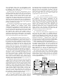
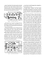
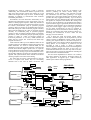
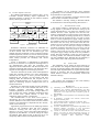
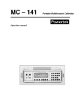
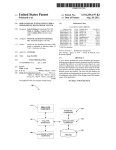
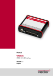
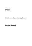
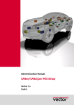
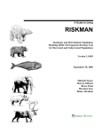
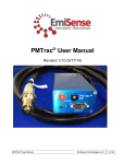
Automated Testing of Electronic Control Units
Compatibility in Vehicle CAN Networks
J. Novák and P. Kocourek
Czech Technical University, Faculty of Electrical Engineering/Department of Measurement, Prague, Czech Republic
Abstract — CAN communication is nowadays the basic way
for information exchange among the Electronic Control
Units (ECUs) that control particular vehicle functionality.
Correct and in-time data delivery from other units is the
underlying presumption of the proper ECU function. As the
CAN is rather complex standard, the detailed testing
of ECU behavior is necessary at all protocol layers of the
communication stack. In order to simplify the testing and to
reduce the human factor influence the automated test site
has been designed and implemented, which realizes more
than 50 physical, link and application protocol layer tests.
For some of them specialized test instruments (like CAN
generator or CAN trigger unit) were designed that allow
influencing the communication events in real-time, as well
as instruments allowing real-time simulation of complete
bus traffic. The use of programmable logic for hardware
implementation allows modifying instruments functionality
without changes in a hardware structure. The time to run
the complete test was reduced more than 10 times compared
to previously used manual measurement and evaluation.
The paper describes methods and their implementation used
for the testing the ECUs behavior at the CAN interface.
I. INTRODUCTION
Each new generation of vehicles (and especially cars)
uses more and more electrical and electronic equipment.
To ensure both the required functionality and low price
simultaneously, the distributed system concept was
adopted to provide the communication path among the
electronic subsystems. An example provided in [1]
declares 32 ECUs and 12 CAN networks in one truck. As
the electronics plays an important role also from the safety
point of view, its correct behavior is required in all
possible working conditions and must be appropriately
tested and evaluated. The tests of electronic components
can be divided into several groups, according to the
development phase in which they are applied. One of
them is the functional testing, focused on the accurate
acquisition of input data and in-time evaluation of correct
outputs used either directly for system control or as the
inputs for other components in the system. It includes both
the component hardware and software testing. In case the
device under test is a part of distributed system, the testing
of communication channel parameters and its behavior
under variety of conditions has a crucial importance, as
errors in one device can cause the whole system failure.
Several communication standards are currently used to
implement distributed systems in vehicles (e.g. CAN,
LIN, MOST). Each of them has its application area – LIN
is used for low-speed communication especially in vehicle
comfort functions system, MOST provides the high-speed
communication path for telematic, multimedia and similar
services, and CAN is being used for medium-speed
communication required by powertrain (ECUs for engine,
brake, airbag, gear and so on) as well as for
communication in comfort and infotainment subsystems.
The CAN communication is therefore the most important
from the point of view of vehicle functionality and safety
and the behavior of ECUs at the CAN interface has to be
properly tested. The first step, described in this paper, is
the standalone ECU testing, where the rest of the system is
simulated, if necessary.
II.
CONTROLLER AREA NETWORK (CAN)
The CAN standard was developed at Bosch (Germany)
in Eighties and its detailed specification can be found in
[2] or [3]. The following description is restricted to the
attributes and features that are necessary for reader to
understand the text below.
Because of the medium access control (MAC) method,
the CAN standard requires a special implementation of the
physical protocol layer. There are two states – dominant
and recessive – that represent logical 0 and logical 1. If
any node on the bus transmits logical 0, there is the
dominant state on the bus, regardless of the levels
transmitted by the other nodes. The recessive level is
found on the bus only if all the nodes transmit logical 1.
This mechanism is used especially in an arbitration field
of CAN frames (which is used to send the frame
identifier) in order to detect possible collisions and to
resolve them. The principle is very simple. If two nodes
start transmitting simultaneously, there is at least one bit
in the arbitration field in which they differ (it is not
allowed for two or more nodes within the system to use
the same frame identifier). The first node sends this bit
e.g. as the recessive bit (logical 1), the second one as the
dominant bit (logical 0). According to the rule defined
above there is a dominant level on the bus and the first
node thus detects the collision. This collision is not
destructive, as the first node stops transmitting and the
second carries on sending the frame. This implementation
of the MAC sub-layer is therefore called CSMA/CR
(Carrier Sense Multiple Access with Collision
Resolution).
Another important feature of the CAN protocol is
a detection of errors in the received data. There are
together four detection mechanisms. Each bit transmitted
on the bus is received back by the transmitting node and
the values are compared. If there is the difference, the bit
error is indicated. Each frame is ensured by CRC code
too. If the received CRC differs from the computed one,
the CRC error is indicated. Each frame also contains
several bits with predefined values. If any of them has the
opposite value, the frame format error is indicated. Next,
each transmitted frame must be acknowledged (from
receiving nodes) by setting an acknowledgement bit into
the dominant state (logical 0). If it is not set, the
acknowledgement error is indicated.
In order to keep the receiver synchronization, the bit
stuffing mechanism is implemented. When more than five
bits of the same value have to be sent, one bit with the
opposite value is inserted at the transmitter site and, of
course, removed at the receiver site. If more than
5 consecutive bits of the same value are received, the bit
stuffing error is indicated. Indication of any type of error
leads the node that detected the error to generating an
error frame (six consecutive bits of the same logical level),
which is encountered by all the nodes in the system and
the data consistency is thus kept.
As the frames are broadcasted to the network (to all the
nodes in the same time), one node, which encounters
reception problems, can therefore block entire
communication by permanent error frame generation. This
is avoided by implementation of error level states. Only
the error active node can actively generate error frames
(using 6 consecutive dominant bits), error passive nodes
can generate only passive error frames (using 6
consecutive recessive bits) and bus off nodes are totally
disconnected from the bus communication. The transition
among these states depends on number of the detected
errors within the transmission and reception phases.
III.
TEST METHODS AND RESULTS EVALUATION
Whole the compatibility test is divided into three parts –
physical, link and application protocol layers testing. At
the physical layer the ECU impedances are measured (e.g.
the presence of internal termination is tested), as well as
voltage levels in dominant and recessive states, the rising
and falling edge lengths, bit rate and sampling point
position within the bit interval. All the parameters can be
measured using the multimeter and oscilloscope except
the position of the sample point. For this test a special
instrument was developed, described below in chapter IV.
At the link layer protocol the tests are rather simpler, as
one can rely on the correct implementation of the CAN
controller in silicon. Nevertheless, the behavior of CAN
controller at the link layer is partially influenced by the
ECU’s application program, especially in case of higher
rate of reception or transmission errors, where the error
status of the controller changes. Some of these changes
(bus-off) can be reset only by the application program and
its timing is also a subject of the test.
The application layer protocols are tested in the largest
number of test points, from simple testing whether all
required frames are being sent by the EUT within the
prescribed time intervals and with correct formats (frame
length, data content) up to the complex testing of EUT
responses in cases when particular received frames are
received with longer period than expected or even missing
at all, when the expected frame format is incorrect (e.g.
different frame length) or frame contains incorrect data.
The access to the ECU diagnostics data structures is
necessary for these complex test points, as the required
ECU response is often the record in the error memory or
the status change of internal diagnostics data.
User of the testing equipment can define all the test
points at particular protocol layers, together with the
expected results and limits. The final evaluation compares
the measured values to the limits and provides the simple
final YES/NO result. According to the user demands the
final test result can have higher “resolution” (the NO
statement can be e.g. divided in two parts – the hard NO,
which clearly says that the EUT cannot be used at all, and
soft NO, which says the EUT doesn’t satisfy the
requirements but it still can be used).
IV. TEST SITE IMPLEMENTATION
The test site consists of two basic parts, the hardware
and software. The hardware implements all the
functionality that requires tight timing and short reaction
times to the CAN bus events, as well as the relay switch
matrix, used to connect the EUT, instruments and power
sources together as required. Software implements the
libraries for instruments control, data acquisition and
partial evaluation, libraries for the CAN network traffic
simulation, libraries for access to diagnostics data and
finally, based on the previously mentioned parts, the
application that executes particular test points and their
evaluation according to the user defined rules.
A. Test Site Hardware Structure
Fig. 1 shows the overall hardware configuration of the
ECU test site. The center is a standard IBM PC
compatible computer (Windows 2000 operating system),
equipped with IEEE488.2 interface (either PCI plug-in
card or external USB interface), which is used to control
standalone instruments – regulated power supply with
internal over current protection and current measurement,
6½ digit multimeter (voltage and resistance measurement)
and DSO oscilloscope (signal shape measurements).
CAN communication can be independently monitored
and logged using PCMCIA based CAN interface and
CANalyzer software [4], but it is not necessary for the
tests to run. Second PCMCIA card provides an access to
the internal diagnostics data. It supports both the CAN
based diagnostics as well as the well-known K line
diagnostics [5] access methods. PCMCIA interface is
provided by PCI to PCMCIA double slot plug-in card.
The second power supply with a fixed output voltage
can be used to power the ECU in tests where the regulated
power supply is used for other purposes (e.g. to generate
common mode voltage for the CAN receiver). Its remote
control using IEEE488 is possible but not required in
currently implemented tests.
7.
Power
Supply
(regulated)
ECU under
Test
1.
4.
Power Supply
+12V
8.
2.
Multimetr
External
Tester Unit
3.
5.
CANalyzer
6.
Oscilloscope
Diagnostics
12.
10.
9.
IEEE 488.2
Interface
Internal
Tester Unit
11.
PCMCIA
Interface
Test Control and Evaluation PC
Figure 1. Test Site Hardware Configuration
The most important and for testing purposes developed
hardware is the Tester Unit, which consists of two parts.
The external part, which structure is shown at Fig. 2,
provides the relay matrix interconnecting all the test
instruments with the tested ECU. Particular connections
can be switched on or off by the configuration block, so
that only the necessary instruments are connected to the
ECU and others do not affect the test procedure.
CAN_BUS
CAN
Termination
CAN
Loads
CAN
Shorts
diag
power
config
DIAG_BUS
Diagnostics
can
trig
Internal
Tester
Part
Oscilloscope
can
CANalyzer
Multimeter
ECU
under
Test
POWER_BUS
Configuration
block
Supervising
block
Triggering
block
+12 V
Power
Supply
Regulated
Power
Supply
Figure 2. External Tester Unit Structure
CAN transceivers for both the high-speed and lowspeed physical layer variants are available and can
exclusively be connected to the internal CAN bus. The
ECU under test can also be connected to the internal CAN
bus. In addition, each CAN line of EUT can be connected
or disconnected separately.
Next three relay blocks are used to simulate CAN lines
short connections (to ground, to power, to ignition control
signal, between them and so on), CAN bus loads
(resistive, capacitive or their combination) and typical
CAN terminations for both physical layer variants.
The ECU power supply, ignition control signal, and
separate wake-up signal are routed via relays as well,
allowing software control of basic ECU functional states.
All the relays (together more than 40) are controlled
independently except their combinations that could lead to
destruction of the tester or tested ECU hardware. The
supervising block doesn’t allow such dangerous
combination (e.g. a short connection of CAN_high signal
to ground and power supply concurrently). Configuration
error flag for the internal tester part is set, if such a
combination is required by the software.
The internal tester unit structure is shown at Fig. 3.
EP1K100
INT
CAN
trigger
Capture
Timebase
Timer
External
Trigger
Configuration
block
RAM
Interface
CAN
Generator
Direct
Values
Sekundární
dohlížecí
SJA1000
konfiguraèní
Interface
ochrana
SJA1000
RAM
POWER
External Unit
Interface
PCI Interface
ALTERA
Capture
ID
Internal Tester
Unit PCI Card
Figure 3. Internal Tester Unit Structure
It is the PCI card containing three basic components –
the large FPGA circuit, SJA1000 CAN controller and
high-speed SRAM (256 kB).
The external unit is connected to the internal one using
the standard DB-15 connector. The shift register
implemented in the external unit CPLD circuit as well as
its counterpart implemented in the internal unit FPGA
circuit are used to control relays and other outputs with no
real-time requirements. All other signals including CAN
and trigger in/out are provided using dedicated signal
lines.
The heart of the internal unit is a 32 bits wide time base
timer, running with 1 µs resolution. This timer content is
used for time stamping of all incoming and outgoing
events, including the CAN events (transmission and
reception of frames, error status changes), external
triggers, internal CAN triggers, CAN Generator events,
and changes in relay matrix configuration. Hardware
capture of all these time stamps allows simple and
accurate time reconstruction of test history, independent
on the reaction time of PC hardware and software. The
timer is also used for time controlled CAN transmission,
which is described below. The similar central timer
concept was already used in CAN monitoring application
described in [6], and it seems to be an optimal approach.
Ordinary CAN reception and transmission is realized
using the SJA1000 controller from Philips, which is one
of de facto CAN controller implementation standards.
Controller is used in the PELICAN mode; its register set
is directly mapped into the PCI address space and can be
accessed anytime. The interrupt request generation is
usually permitted for transmission, reception and status
change events. This signal is used internally to capture the
event time stamp. If the accurate timing of CAN frames
transmission is required, a dedicated hardware mechanism
is implemented that guarantee in time transmission. In this
case the frame content, received from the software, is
completed with the time stamp of required transmission
time. The frame data are written into the controller, but
instead of immediate “transmit” command the required
time stamp is written into the dedicated register in FPGA.
In a moment the timer reaches its value the “transmit”
command is written into the controller by FPGA
hardware. This approach ensures the accurate and absolute
timing of the start of transmission (unless the MAC
uncertainty), the actual transmission time (including the
MAC uncertainty) is then captured as described above.
As some tests may require more than usual transmission
functionality, a special instrument, CAN Generator, was
developed. Its detailed functionality is described in [7]. In
order to be used in the automated test site, its
implementation was modified, especially from the point of
view of its triggering and event time capturing. Generally,
the CAN Generator allows transmitting of CAN frames
consisting of predefined bit sequence. Several flags that
modify the way it is transmitted to the bus define each bit
in the sequence. Particular flags define the logical value of
a bit, whether it is an arbitration field bit (if set, in case on
reception of dominant value while sending the recessive
one the transmission is finished), whether it is the last bit
of the transmitted frame (if set, by transmitting of this bit
the frame transmission finishes), whether it is the ACK bit
(if received recessive, the acknowledge error status flag is
set) and whether its logical value has to be checked by
reading back when it is transmitted (if set, the check of
specified ID (or range) on the bus. An example is the
selective jamming of chosen frames during their
transmission. As the ordinary CAN controller provides
this information too late (when jamming is no longer
possible), the CAN Trigger module was developed, which
provides the early trigger functionality. Up to 16 ID and
mask register pairs are defined and the content of masked
ID registers is compared with masked IDs coming from
the bus. In case of matching a corresponding time stamp is
captured and the trigger is generated, which can be used to
synchronize CAN Generator or any standalone instrument
using the external trigger output. The trigger generation
can be either asynchronous (as fast as possible) or
synchronized by the reconstructed CAN bus timing. This
feature (in cooperation with CAN Generator) allows e.g.
disturbing the transmission of ECU under test and
bringing it into bus-off state.
Fig. 4 shows the CAN and trigger signals routing
structure. Particular signals can be replaced by forced
values according to ModDirect register content. It allows
reaching the required behavior of related subsystem or
simulating some events during software development and
testing phases. As an example it is possible to set the
SJA1000 in such a mode, in which it internally
acknowledges incoming frames but the acknowledgement
doesn’t propagate outside the tester. In this case it is
seemed for the tested ECU to be the only node on the bus,
while we are able to capture its transmission including the
data content of the transmitted frames.
The last block implemented in FPGA is an ordinary
PCI Slave interface IP function, developed earlier for
other application. It supports up to 1 MB of memory
address space and the interrupt generation.
transmitted bit value by reading it back is ignored).
Additionally, each bit definition contains a pointer to the
table of bit time intervals, which may contain up to 128
different bit lengths with a step of 20 ns. It offers enough
flexibility to simulate e.g. transmission clock variations
and similar phenomena.
Nevertheless, the CAN Generator functionality is not
limited to the transmission of one single frame. User can
define so called program sequence, which may include not
only the SEND instruction to transmit the frame, but also
the GOTO (unconditional jump at specified program
position), DELAY (waiting for predefined time interval),
SETVAR (setting the value of selected program variable),
DECVAR (decrementing the value of selected program
variable), IF (conditional jump at specified program
position if value of selected variable equals to instruction
parameter), TEST (conditional jump at specified program
position if result of <value of selected variable &
instruction parameter> is not zero), ARM (transmit the
frame after the trigger has occurred) and END (stop
program execution).
CAN Generator offers up to 256 different frames in one
sequence and up to 128 different lengths of bit period. The
frame definitions are stored in external RAM, the bit
timetable as well as the program sequence is stored in the
internal FPGA RAM (higher speed access is required).
External RAM access from the PCI side is forbidden when
CAN generator is running to prevent unintentional writes.
The flexible definition of frames and program sequences
together with synchronization from outside events allows
realizing complex tests with accurate timing.
For some tests the precise synchronization to the bus
events is required even before they are successfully
finished. This is the case of frame occurrence with
ModDirect [11]
0
ValDirect [11]
ValDirect [2]
INT
CAN LEVEL
- Read
- Write
ValDirect [11]
1
log.1 - recessive
log.0 - dominant
ModDirect [2]
0
SJA1000
1
AND
CAN RXD
ValDirect [2]
ModDirect [1,0]
AND
CAN RXD
00
01
CAN TXD
1
1
CAN TXD
10
0
ValDirect [0]
11
ModDirect [12]
ValDirect [3]
ValDirect [5]
ModDirect [3]
ValDirect [6]
ModDirect [5]
0
CAN RXD
CAN gen
CAN
ValDirect [0]
1
ModDirect [6]
ValDirect [3]
ModDirect [8,7]
0
00
CAN TXD
1
01
TRIG
10
0
1
NOT
ValDirect [6]
OR
11
ValDirect [7]
ValDirect [4]
TRIG IN
ValDirect [7]
TRIG
ModDirect [4]
TRIG OUT
0
CAN RXD
CAN trig
1
ValDirect [4]
ModDirect [9]
ValDirect [9]
1
sum TRIG
ValDirect [9]
ModDirect [10]
0
0
NOT
Figure 4. Internal CAN and Trigger Routing
1
ValDirect [10]
B. Test Site Software Structure
The software implementation is shown at Fig. 5. It has
a modular structure allowing simple replacement of
particular modules or changes in their behavior without
directly affecting the other ones.
Application
Software
Instrument DLL
Library
Third party
Driver + VISA
Library
IEEE488.2
Interface
Simulation and
Monitoring
Thread (CAN)
CAN
Communication
Database
Config. DLL
Library
Diagnostics
Thread
Driver + DLL
Library
Third party
Driver + DLL
Library
PCI Tester
Card
PCMCIA
Diagnostics
Figure 5. Software Structure
Standalone instrument connected via IEEE488 are
controlled through the Instrument DLL library. It consists
of three classes, each for one instrument type. The
member functions implement not only instrument settings
and data acquisition, but also (in case of oscilloscope) the
measured signal parameters evaluation. Incorporating the
VISA library provides the flexibility and vendor
independence.
Access to diagnostics is implemented in standalone
thread, as in some test it is required for the diagnostics to
run simultaneously with other test procedures. The
diagnostics thread communicates with the main thread via
messages and shared data structures. The third party DLL
supports several diagnostics and transport protocols.
The driver and DLL for the PCI Tester Card implement
simple but powerful interface to the entire functionality
described in the chapter A. Driver provides automated
transmission and reception of CAN frames with time
stamping. Both the transmission and reception can be
queued, transmitted frames can be put back to receive
queue for monitoring purposes, stamped with time of
actual transmission.
Simulation and monitoring thread provides simulation
of other nodes in the CAN network that must not be
therefore physically connected. Additionally, the
simulation parameters can be widely changed before as
well as during the running simulation. Simulation takes
into account some special features in data, like
multiplexes, frame counters or checksums.
The communication in the whole CAN system is
described by the CAN Communication Database, which
contains definition of all nodes, frames and their internal
structure. This information is imported from the .dbc file,
which is also used in [4].
Application program then uses all underlying software
layers for test conditions setup and ECU response
evaluation. Creating new tests using the developed
libraries is very easy, as far as the required functionality is
supported by the hardware. To add or change the single
test behavior takes about an hour (if the new test is not
completely different from tests implemented till now).
The possibility of test generation using graphical
programming is now evaluated; it depends on the current
and potential user requirements.
In the future it is expected to export the measured data
values and their evaluation into the XML.
The software is currently running in Windows 2K/XP
environment and it was developed using Microsoft C++.
V. TEST SITE EVALUATION
The simple example is described here to show how
strong support is provided for the ECUs testing by the
system described above. User wants, for example, to test
whether the EUT writes required error into the error
memory in depenedence on power supply value. When the
test is done manually, the wiring of power lines, CAN and
diagnostics must be prepared at first. User has to switch
ECU on, set the required power supply voltage, and start
the simulation of the rest of network so that the conditions
that lead to the error entry are avoided. Then the error
memory has to be cleared so that the reference conditions
are set. Now the test can start by the change of network
simulation parameter that leads to the error entry into the
EUT’s error memory. This entry must be verified, error
memory cleared and the test can continue in loop with
new power supply voltage until the error entry treshold is
found. The final evaluation is quite easy and consists of
checking whether the measured threshold voltage falls
into the predefined range. Running this test manually is
about 5 times slower than using the test automation.
VI.
CONCLUSION
The automated site for testing the ECUs behavior at
CAN interface was designed and developed. Its modular
structure in both the hardware and software design allows
fast and simple implementation of required tests and their
changes, if necessary. The use of programmable logic
allows flexible extension of functionality without the
hardware redesign.
ACKNOWLEDGMENT
This research was supported by the Czech Ministry
of Education project No. 1M0568.
REFERENCES
[1]
[2]
[3]
[4]
[5]
[6]
[7]
T. Bardelang, “CAN im Hardware in the Loop (HiL) Simulator Erfahrungen mit vernetzten Fahrzeugfunktionen und deren
Prüfung im Rahmen der Anwendung eines HiL-Simulators für
schwere Lkw, Vector Symposium CAN im Nutzfahrzeug, May 12,
2004, Stuttgart.
R. Bosch, GmbH, “CAN Specification 2.0”, Robert Bosch GmbH,
1991.
K. Etschberger, “Controller Area Network”, IXXAT Press,
Weingarten, Germany, 2001.
Vector Informatik, GmbH, “CANalyzer User Manual”, 2003.
ISO 9141, Road vehicles – Diagnostics systems – Requirements
for interchange of digital information
P. Pfeifer, “Multifunctional Programmable Single-Board CAN
monitoring Module”, Proceedings of 10th International
Conference FPL2000, Villach, Austria, pp. 163-168, 2000.
J. Novák, A. Fried, and M. Vacek, “CAN Generator and Error
Injector”, Proceedings of IEEE International Conference on
Electronics, Circuits and and Systems ICECS2002, CD ROM, pp.
967–970,
September
2002,
Dubrovnik,
Croatia.