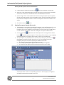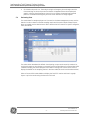
1
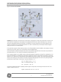
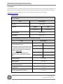
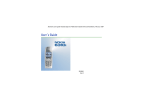
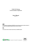
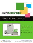
Implementing TOC Analysis Standard Operating Procedure (SOP) Sievers M9 Lab or Portable TOC Analyzer with GE Autosampler Analytical Instruments www.geinstruments.com 300 00283 Implementing Total Organic Carbon Analysis Sievers M9 with Autosampler Standard Operating Procedure Table of Contents M9 TOC ANALYZER STANDARD OPERATING PROCEDURE (SOP) ............................. 2 1.0 PURPOSE .......................................................................................................................................................... 2 2.0 SCOPE ................................................................................................................................................................ 2 3.0 TOC METHODOLOGY ................................................................................................................................... 2 Figure 1. Sievers M9 Schematic: ................................................................................................................... 3 4.0 MATERIALS ....................................................................................................................................................... 5 5.0 PROCEDURES.................................................................................................................................................. 6 5.1 Basic Instrument Preparation ......................................................................................................... 6 5.2 Performing TOC Analysis with User and System Protocols ............................................... 8 5.3 Running Emergency Samples & Protocols ............................................................................. 10 5.4 Reviewing Data ................................................................................................................................... 11 References ...................................................................................................................... 13 Revision History ............................................................................................................. 14 -1- 300 00283 Rev. B GE Analytical Instruments © 2014 Implementing Total Organic Carbon Analysis Sievers M9 with Autosampler Standard Operating Procedure M9 TOC ANALYZER STANDARD OPERATING PROCEDURE (SOP) 1.0 PURPOSE The purpose of this Standard Operating Procedure (SOP) is to describe the basic methodology, materials for operations, instrument preparation, and performance of user defined or system protocols of Sievers Model M9 Laboratory or Portable instruments with the use of an autosampler. 2.0 SCOPE This document applies to all employees who will analyze Total Organic Carbon (TOC) samples. It is recommended that separate SOPs are created by the user for maintenance activities, sample plans, creating user levels for the DataPro2 software, data export, reporting and documentation on forms or worksheets, and troubleshooting. Please reference DLM 77000 and the pertinent chapters associated with the above mentioned steps. This procedure is only applicable for the Sievers M9 TOC Analyzer that has been previously qualified (IQ/OQ/PQ) with documents DVL 77100 and DVL 77400. 3.0 TOC METHODOLOGY Analytical technologies used to measure TOC share the objective of completely oxidizing the organic molecules in an aliquot of sample water to carbon dioxide (CO2), measuring the resultant CO2 concentration, and expressing this response as carbon concentration. A variety of technologies are available to measure TOC. Differences across the various TOC manufacturers’ devices reside with the approach used to oxidize organics, as well as the method used to detect the resultant CO2.. The following schematic for the Sievers M9 Laboratory (Figure 1) Analyzer demonstrate the working components of the TOC method. -2- 300 00283 Rev. B GE Analytical Instruments © 2014 Implementing Total Organic Carbon Analysis Sievers M9 with Autosampler Standard Operating Procedure Figure 1. Sievers M9 Schematic: Oxidation: After sample is introduced into the Analyzer, 6M phosphoric acid (H3PO4) (referred to as Acid in the user interface) is injected into the sample at the programmed flow rate to reduce sample pH to 2 and 15% ammonium persulfate ((NH4)2S2O8) (referred to as Oxidizer in the user interface) to promote oxidation of the organics; this allows for accurate measurement of TC and IC simultaneously. The sample travels through a mixing coil and on to a stream splitter. If the optional Inorganic Carbon Remover (ICR) unit is utilized, additional acid is added to the sample to remove excess IC by the ICR. In the ICR, IC is removed by vacuum degasification. The stream splitter divides the sample stream into two equal but separate flows. One stream is processed for the measurement of IC; the other is processed for measurement of TC. The TC stream passes to an oxidation reactor where the sample is exposed to UV light. The combination of UV light and, depending on the application, persulfate oxidizes the organic compounds in the sample, converting carbon to CO2. The reactor is a spiral quartz tube wrapped around the UV lamp. The UV lamp emits light at 185 and 254 nm resulting in the formation of powerful chemical oxidizing agents in the form of hydroxyl radicals produced by the photolysis of water (eq. 1) and persulfate (eq. 2, 3): H2O + hv (185 nm) OH· + H· (1) S2O8-2 + hv (254 nm) 2 SO4·- (2) SO4·- + H2O HSO4- + OH· (3) The hydroxyl radicals (OH·) will completely oxidize organic compounds, converting the carbon atoms of the organic compound into CO2. Organic Compounds + OH· CO2 + H2O (4) -3- 300 00283 Rev. B GE Analytical Instruments © 2014 Implementing Total Organic Carbon Analysis Sievers M9 with Autosampler Standard Operating Procedure When the TOC concentration in the sample is low (<1 ppm), complete oxidation can usually be achieved using only the hydroxyl radicals from the photolysis of water (eq. 1) without the addition of persulfate. The IC stream passes through a delay coil, which is designed to make the total transit time of the IC stream through the Analyzer the same as the transit time of the TC stream through the Analyzer. When the TC stream exits the oxidation reactor and the IC stream exits the delay coil, each stream moves to the CO2 Transfer Module. The CO2 Transfer Module is a patented design, utilizing a gas-permeable membrane that allows the transfer of CO2 across the membrane. The membrane separates the sample side of the Analyzer from the DI side. The DI side of the Analyzer is a closed loop, and consists of two conductivity cells— one for the TC stream and one for the IC stream—a DI water pump, DI water reservoir, and ion exchange resin (resin bed). Detection: Membrane conductometric detection is then employed to quantify the amount of IC and TC in the sample. CO2 from the sample passes through the membrane into the DI water supplied by the integrated DI Loop, while interfering compounds and other oxidation by-products are blocked by the membrane and remain on the sample side. The CO2 forms carbonic acid upon reaction with water, and the carbonic acid disassociates into hydrogen ions and bicarbonate ions: CO2 + H2O H2CO3 H+ + HCO3- (5) DI water is continuously pumped through the DI side of the Analyzer, collecting the H+ and HCO3- ions and H2CO3 and CO2 molecules from the CO2 transfer modules, delivering it to the conductivity cell for measurement. Then the ion exchange resin removes the HCO3- and other ions. The water is then pumped back to the CO2 transfer module to repeat the sequence. The TC and IC conductivity cells each contain a thermistor, and all conductivity readings are temperature corrected. The CO2 from the TC and IC sample streams are measured by the respective conductivity cells, and the conductivity readings are used to calculate the concentration of TC and IC. Once the values are measured, TOC is calculated as the difference: TOC = TC - IC (6) -4- 300 00283 Rev. B GE Analytical Instruments © 2014 Implementing Total Organic Carbon Analysis Sievers M9 with Autosampler Standard Operating Procedure 4.0 MATERIALS This standard operating procedure requires specific materials and standards. The following table highlights the specific items that are needed for the M9 Instrument and test procedures. Not using these items can impact the success of the test procedures. All items can be ordered from GE Analytical Instruments. www.geinstruments.com. Materials Table M9 Consumables ITEM PART NUMBER UV Lamp CARK 35010 Reagents Oxidizer Acid CAPF 90300 CAPF 90310 Resin Cartridge CASM 77250 Pump Heads CAPK 77207 M9 Test Standards for System Protocols & Materials for Testing ITEM PART NUMBER Calibration & Verification The M9 offers multiple concentrations levels for calibration and verification. If you prefer a multi-point calibration set, then the part number is CSTD 77000. The part numbers to the right are for calibration and or calibration/verification only. 1 ppm Cal: CSTD 90001 1 ppm Cal/Ver: CSTD 90016 5 ppm Cal: CSTD 90002 5 ppm Cal/Ver: CSTD 90017 10 ppm Cal: CSTD 90003 10 ppm Cal/Ver: CSTD 90018 25 ppm Cal: CSTD 90004 25 ppm Cal/Ver: CSTD 90019 50 ppm Cal: CSTD 90005 50 ppm Cal/Ver: CSTD 90020 System Suitability CSTD 31004 SDBS Suitability CSTD 90039 Accuracy and Precision CSTD 31013 Certified Vials CHMI 90606 Dual Use Conductivity & TOC Vials CHMI 77500 -5- 300 00283 Rev. B GE Analytical Instruments © 2014 Implementing Total Organic Carbon Analysis Sievers M9 with Autosampler Standard Operating Procedure 5.0 PROCEDURES 5.1 Basic Instrument Preparation This standard operating procedure is applicable to the Sievers M9 Laboratory or Portable Analyzer with the use of the GE Autosampler and the DataPro2 software. Most of the procedures located in the product manual can be found in DataPro2 under the HELP icon. While in DataPro2, selecting the PRODUCT MANUALS tab displays the following options and manuals: 5.1.1 Visual Inspection of the Instrument Prior to Use Prior to analysis, remove the right side cover of the analyzer to visually inspect the critical components. The analyzer consists of five critical subsystems that should be routinely checked for finger tight connections or any leaks prior to analysis: Sample Inlet System—A dual pump system and a sample line connection to the analyzer. Chemical Reagent System—Reagent reservoirs and syringe pumps used to deliver chemical reagents into the sample. UV Reactor—The reactor is a spiral quartz tube wrapped around an ultraviolet (UV) lamp used to oxidize the sample. CO2 Measurement Module—Consists of a CO2 Transfer manifold (a fluidics block with separate TC and IC channels to the gas-permeable membranes, that allows the transfer of CO2) TC and IC channel. Fluidics Module—Contains the TC and IC sample pumps and the DI water loop (DI water reservoir, ion exchange resin column, and the circulation pump. 5.1.2 Reviewing Consumables Status, Errors and Warnings Prior to Use Start or initiate DataPro2. From the home screen review the consumables status and alerts tabs. Switching views can be achieved by selecting the tab. Contact appropriate individuals if consumables need to be replaced or if there are serious warnings/errors observed. -6- 300 00283 Rev. B GE Analytical Instruments © 2014 Implementing Total Organic Carbon Analysis Sievers M9 with Autosampler Standard Operating Procedure 5.1.3 Replacing Components during Instrument Preparation If components need to be replaced during the instrument preparation, then use the product manual located in the HELP section of DataPro 2. During replacement, be sure to record events appropriately in company documentation and update the status on the analyzer. 5.1.4 Performing a Reagent Flush Prior to Analysis The analyzer will prompt you to perform a reagent flush prior to analysis. Alternatively, the procedure for performing this step can be found in DataPro2 under the HELP icon and selecting the Analyzer User’s Manual. 5.1.5 Selecting a Compendia for Testing The Sievers M9 Analyzer can be used for TOC and Conductivity Compendia water testing or cleaning validation/verification samples. It is important to select the appropriate compendia if needed for regulatory reporting. The pharmacopeia will need to be selected via the instrument’s configuration settings by selecting the CONFIGURATION icon. The following graphic will be displayed on the instrument’s screen: Please note that the pharmacopeia specifications for TOC will be set based on the system suitability test and the “limit response” derived during that analysis. Stage 1 Conductivity temperature tables will also be loaded for the analysis if conductivity is used for the method. 5.1.6 Recommended Flow Rates for User Designed TOC Methods Guidance on the acid and oxidizer flow rates can be found under the HELP icon in DataPro2. When selecting the recommended flow rates the following graphics are displayed for the acid and oxidizer reagents: -7- 300 00283 Rev. B GE Analytical Instruments © 2014 Implementing Total Organic Carbon Analysis Sievers M9 with Autosampler Standard Operating Procedure 5.2 Performing TOC Analysis with User and System Protocols 5.2.1 Developing User Defined TOC Methods and Protocols The M9 TOC Analyzer utilizes a software program to execute system protocols, user-defined protocols, sample vials, and standard solutions. DataPro2 uses the terminology Methods and Protocols to define and run vials containing the standards used for the day to day operation. Methods are a set of parameters assigned to each vial, while protocols are a sampling instruction for one or more vials with applied methods. DataPro2 TOC Method Development: The M9 TOC method is a set of parameters assigned to each vial that makes up the protocol. In order to create a method: Launch DataPro2. On the home screen, select the setup tab to display the Method Panel. Develop user defined methods as demonstrated in the figures below: Select the amount vials on the autosampler rack display needed for your method by clicking on the vial with the mouse and click and drag over the selected number of vials needed: The TOC Method for each vial in the protocol can have the following parameters selected for the method name, type, critical function (turbo, ICR, TOC, or Conductivity) flush time (seconds), Repeats (10), and Rejects (0). Develop the method based on the intended use of the sample. Once the method is developed, save the method by selecting the “save” icon. After the TOC Method has been saved, enter the sample name for each vial. Once the sample names have been entered, save the method by selecting the “save” icon. -8- 300 00283 Rev. B GE Analytical Instruments © 2014 Implementing Total Organic Carbon Analysis Sievers M9 with Autosampler Standard Operating Procedure 5.2.2 5.2.2 After the method is developed, it will be applied to a unique protocol by selecting the “save” protocol icon: DataPro2 will require a protocol title for each unique protocol developed or designed. Running User Defined TOC Protocols Launch DataPro2. Select the Favorites Icon Select the specific protocol that was previously design from the list. Once the protocol is loaded, enter the lot number of the standards or vials (or leave the field blank) and click OK. Load the sample vials and avoid touching the septa to protect against introducing foreign particles. Place the vials in the GE Autosampler vial rack so they match the configuration shown in the Vial Configuration and Protocol areas on the screen. Click the Run Protocol and click the Protocols tab. button. Running System TOC Protocols DataPro2 provides a full set of automated system protocols for calibration and periodic performance checks. Protocols for these options automatically appear in the DataPro2 list of system test procedures under the Favorites Icon and selecting the System Protocols tab. The automated system protocols are broken down into three sections that include verification, validation (if needed to re-perform) and calibration. -9- 300 00283 Rev. B GE Analytical Instruments © 2014 Implementing Total Organic Carbon Analysis Sievers M9 with Autosampler Standard Operating Procedure Running the M9 System Protocols with DataPro2: 5.3 Launch DataPro2. Select the Favorites Icon Select one of the automated system protocols from the list. Once the protocol is loaded, enter the lot number of the standards (or leave the field blank) and click OK. Open the bag of each of the standards and avoid touching the septa to protect against introducing foreign particles. Place the standards vials in the GE Autosampler vial rack so they match the configuration shown in the Vial Configuration and Protocol areas on the screen. Click the Run Protocol and click the System Protocols tab. button. Running Emergency Samples & Protocols The Emergency Protocol feature is available for pausing a User-Defined protocol in order to create and run a sample analysis using an Emergency Protocol. The vials for this Emergency Protocol are loaded into the Emergency Protocol rack that is located directly in front of the GE Autosampler tower and to the right of the optional Rinse Station. On the Home screen (while the User-Defined protocol is running), click the Pause button . DataPro2 pauses analysis or if the analysis of the vial has not yet completed, a message appears that analysis will pause at the end of the vial (sampling). After pausing the User-Defined protocol, click the Set up Emergency Protocol icon that appears to the left of the Run Protocol icon . The icon changes to the Close Emergency Protocol icon and the following are added to the screen: The Protocol field populates with Emergency Protocol. The Emergency Rack graphic appears above the Sample Rack graphic. The Setup tab view appears with the Method panel and Protocols table. Load the sample vials into the Emergency Protocols rack located in front of the GE Autosampler tower. Click the corresponding positions on the Emergency Rack graphic and apply the appropriate method to each vial. - 10 - 300 00283 Rev. B GE Analytical Instruments © 2014 Implementing Total Organic Carbon Analysis Sievers M9 with Autosampler Standard Operating Procedure 5.4 Click the Run Protocol icon. The analysis using the Emergency Protocol begins and the time remaining for the entire protocol and each vial appears above the Sample Rack graphic. Click the Close Emergency Protocol icon to resume the paused User-Defined protocol. The additional Emergency Protocol screen elements no longer appear. Reviewing Data The results data for sample analyses run is located on the Data Management screen. Use the Results List tab to view all or filtered sampling results and the various levels of detail. Export data, as needed. Use the Results Search tab to define criteria for search for specific categories, fields, and values. First select either Database (the default view showing current results stored in DataPro2) or Archive to browse on the computer or network for archive files. Select All or Filtered data (click CHANGE to display the Filters dialog box with fields for setting filter criteria.) Select a line to display the details for the sampling results in the lower table. (Show All must be selected also.) Select a line and click SHOW GRAPH to display the TOC/IC/TC results and time in a graph. Export or print the results using the buttons on this tab. - 11 - 300 00283 Rev. B GE Analytical Instruments © 2014 Implementing Total Organic Carbon Analysis Sievers M9 with Autosampler Standard Operating Procedure Results Search - Select either Database (the default view showing current results stored in DataPro2) or Archive to browse on the computer or network for archive files. In the Quick option view, use the Category, Field, Criteria, and Value (and related) fields to define the filters for the search results and click SEARCH. DataPro2 displays the protocol results fitting this criteria in a new table on this tab. Use the buttons on the left to show a graph, export the data, or print the data. - 12 - 300 00283 Rev. B GE Analytical Instruments © 2014 Implementing Total Organic Carbon Analysis Sievers M9 with Autosampler Standard Operating Procedure References This section should be filled out with customer/site specific SOPs, forms or documents. - 13 - 300 00283 Rev. B GE Analytical Instruments © 2014 Implementing Total Organic Carbon Analysis Sievers M9 with Autosampler Standard Operating Procedure Revision History This section should be filled out with customer/site specific SOPs, forms or documents. - 14 - 300 00283 Rev. B GE Analytical Instruments © 2014