1
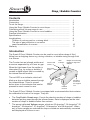
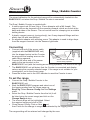
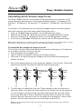
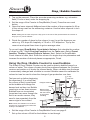
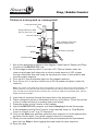
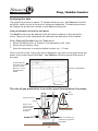
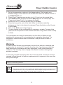
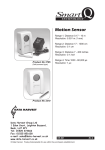
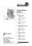
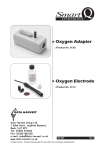
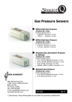
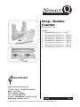
Smart
Q
TECHNOLOGY
Drop / Bubble
Counter
(Product No. 3266)
Ranges:
1. Drop/Bubble Count: 0 – 10 000
2. (23 drops/cm3) Volume: 0 – 120 cm3
3. (24 drops/cm3) Volume: 0 – 120 cm3
4. (25 drops/cm3) Volume: 0 – 120 cm3
5. (26 drops/cm3) Volume: 0 – 120 cm3
6. (27 drops/cm3) Volume: 0 – 120 cm3
7. (28 drops/cm3) Volume: 0 – 120 cm3
8. (29 drops/cm3) Volume: 0 – 120 cm3
DATA HARVEST
Data Harvest Group Ltd
1 Eden Court, Leighton Buzzard,
Beds, LU7 4FY
Tel: 01525 373666
Fax: 01525 851638
e-mail: [email protected]
www.data-harvest.co.uk
DS 066
© Data Harvest. Freely photocopiable for use within the purchasers establishment.
No 2
Smart
Q
Drop / Bubble Counter
TECHNOLOGY
Contents
Introduction...............................................................................................
Connecting...............................................................................................
To set the range........................................................................................
Using the Drop / Bubble Counter to count drops......................................
Calculating which Volume range to use...................................................
Using the Drop / Bubble Counter to count bubbles..................................
Practical information.................................................................................
Specifications...........................................................................................
Investigations ..........................................................................................
Titration of a strong acid vs. a strong alkali .......................................
The rate of gas production in an active
yeast fermentation of sucrose.............................................................
Warranty ................................................................................................
1
2
2
3
5
6
7
8
8
9
10
11
Introduction
The Smart Q Drop / Bubble Counter can be used to count either drops of fluid
falling from a dropping device e.g. during a titration, or bubbles rising through fluid
in a column.
The Counter has an infrared emitter and
a receiver separated by a 56 mm air gap.
When the light beam from the emitter is
interrupted (e.g. by a drop or bubble) it
creates a digital signal that is counted by
the internal counter module.
The red LED is an indicator, which will
blink as a drop or bubble passes through
the infrared beam. There is a small
button close to the indicator that can be
pressed to reset a count to zero.
Sensor lead
socket
LED
indicator
Ridges and mounting
thread for alignment
adapter
Zero reset
button
56 mm
air gap
Infrared
emitter
Infrared
receiver
Mounting
thread for
the support
rod
The Smart Q Drop / Bubble Counter is equipped with a microcontroller that contains
the calibration for each of its ranges. They are:
•
•
The Drop/Bubble Count range. Counts the absolute number of drops or bubbles detected as they pass through the infrared beam. Data is displayed as the total number of drops or bubbles rather than volume.
The preset calibrated Volume ranges, which are 23 drops/cm3, 24 drops/cm3, 25 drops/cm3, 26 drops/cm3, 27 drops/cm3, 28 drops/cm3 and 29 drops/cm3. When any of these ranges are selected the drops counted are automatically converted and displayed as Volume in cm3.
Smart
Q
Drop / Bubble Counter
TECHNOLOGY
The stored calibration for the selected range will be automatically loaded into the
EASYSENSE unit when the Drop / Bubble Counter is connected
The Drop / Bubble Counter is supplied with:
• A steel support rod (80 mm long x 10 mm diameter with a M6 thread). This
support rod can be screwed into the mounting threads, which are found at the base and sides of the Sensor. The rod can be used for clamping into a suitable holding device.
• A plastic reagent reservoir (syringe body), two 3-way stopcock fittings and two plastic tips (all with twist fittings).
• An alignment adapter with securing screw. This adapter is used to align drops from the reagent reservoir into the Sensors light beam.
Connecting
•
•
•
•
Connect one end of the sensor cable
(supplied with the EASYSENSE unit)
into the shaped socket on the Counter
housing with the locating arrow on the
cable facing upwards.
Sensor cable with locating
Connect the other end of the sensor
arrows facing upwards
cable to the input socket on the
EASYSENSE unit (with the locating arrow facing upwards). The red LED will light.
The EASYSENSE unit will detect that the Counter is connected and display
values using the currently selected range. If the range is not suitable for your investigation, set to the correct range.
Press the button next to the LED indicator to reset the Counter to zero.
Product code 3266
Drop Counter / Bubble Sensor
To set the range
•
•
•
•
•
Connect the Drop / Bubble Counter to the
EASYSENSE unit.
Start the EASYSENSE program and select one of
the logging modes from the Home page e.g.
EasyLog. Select Sensor Config from the Settings
menu.
Select the Drop / Bubble Counter from the list (it will
be listed using its current range) and click on the
Change Range button.
The current range will be highlighted. Select
the required range and click on OK.
Close Sensor Config. Click on New
and
then Finish for the change in range to be detected by the logging mode.
The range setting will be retained until changed by the user.
Smart
Q
Drop / Bubble Counter
TECHNOLOGY
With some EASYSENSE units it is possible to set the range from the unit. Please
refer to the EASYSENSE unit’s user manual.
Using the Drop / Bubble Counter to count drops
Setting up the reagent reservoir and alignment adapter
The plastic reagent reservoir and tip supplied with the Counter will provide drops
within the preset calibration ranges. The reservoir has two stopcocks. One stopcock
is used to set the rate of flow from the reservoir and therefore the drop rate. The
other stopcock is used to turn the drops on and off.
Assemble the plastic reagent reservoir
• Screw a stopcock fitting onto the syringe body with a gentle half turn. Fit the second stopcock onto the first, then the tip. Turn both threaded collars to secure the fittings in place (twist back to release).
Adjustment valve
Drops on or off
The combination of two three-way stopcocks is used to control the flow of fluid from
the reservoir. The top stopcock is used as an adjustment valve to set the rate of flow
and therefore the drop rate from the reservoir. The lower stopcock is used in either
an open or closed position to turn the drops on and off.
Closed - Fluid will not flow when the
tap is in either of these positions
Open - Fluid will flow when the
tap is in either of these positions
The line of the blue handle indicates the ports of the stopcock that are linked and
open.
Note: Leave the white sealing blank fitted to the side port of the stopcock.
• Turn both stopcocks into the closed position. Clamp the reagent reservoir into place using the alignment adapter.
Using the alignment adapter
The alignment adapter has been provided to give an easy way of aligning drops
through the infrared beam of the Counter.
Smart
Q
Drop / Bubble Counter
TECHNOLOGY
The adapter has three holes in its flat plate.
1. The large hole will accept a pH or Conductivity
electrode.
2. The small hole marked with ‘target’ lines is for the
tip of the reagent reservoir or burette.
3. The other small hole is suitable for a Temperature
Sensor (if used).
Small hole for
Temperature
sensor
Large hole for
electrode
Small hole for
reagent reservoir
Attach the alignment adapter to the Counter:
• Part screw the Pozidriv pan-head screw supplied into the mounting thread
between the two ridges in the centre of the Counter.
• Slide the mounting arm of the adapter behind the screw head.
• Gently tighten the screw, do not over tighten.
Drop / Bubble
Counter
Zero button
Alignment
adapter
Pozidriv
panhead
screw
•
2
Screw the support rod into the appropriate mounting
thread (there is a choice of three positions) and
clamp to a stand. Make sure the Counter is level and
the LED indicator is visible to the user.
Product code 3266
Drop Counter / Bubble Sensor
1
3
Support rod position
Position the reagent reservoir in the alignment adapter
• Locate the tip of the reagent reservoir into the hole that has ‘target marks’ around it. When correctly seated the tip will be visible below the adapter plate.
• Use a clamp to support the body of the reservoir. Do
not over tighten. Check the reservoir is vertical.
Reagent
reservoir
tip
The drops produced will fall through and cut the infrared
beam without further adjustment.
Hole with target marks
If the reagent reservoir and alignment adapter are not used
There is an indented line on the housing of the Counter
(above the emitter and receiver). The dropper should be
aligned so that falling drops will cut through an imaginary line
drawn between these indents. Use the LED to help align the
drops, it will blink each time a drop interrupts the beam.
Imaginary
line
Smart
Q
Drop / Bubble Counter
TECHNOLOGY
Calculating which Volume range to use
The Drop / Bubble Counter can be used record data directly as a volume (in cm3)
measurement by selecting one of the preset calibrated ranges - 23 drops/cm3, 24
drops/cm3, 25 drops/cm3, 26 drops/cm3, 27 drops/cm3, 28 drops/cm3 and 29 drops/
cm3.
If accuracy is not critical and you are using the reagent reservoir and tip supplied
with a low viscosity liquid (like water) and the flow rate set to: • Fast e.g. 10 plus drops per second, use the 24 drops/cm3 range.
• Medium e.g. between 5 - 10 drops per second, use the 25 drops/cm3 range.
• Slow e.g. between 1.5 - 5 drops per second, use the 26 drops/cm3 range.
• Very Slow e.g. less than 1.5 drops per second, use the 27 drops/cm3 range.
Note: When used with a pH or Conductivity Sensor, the flow rate needs to be very slow (less than 1.5 drops
per second) to allow the Sensor time to settle to a new reading after addition of the titrant.
To calculate the number of drops in a cm3
The volume of a drop of fluid (and therefore the number of drops per cm3) depends
on a number of factors. These include the:
• Size and shape of the dropper end.
• Type of solution (its density, viscosity and surface tension).
• Flow rate of the liquid through the dropper end (the slower the dropping the smaller the drop).
1. Set up the reagent reservoir in the alignment adapter of the Counter. Close both stopcocks (a) and fill the reservoir with the solution being used.
(a)
Closed
(OFF)
Closed
(OFF)
Closed
(OFF)
Open
(ON)
(b)
Open slowly
to adjust drop
rate
Partly
Open
Open
(ON)
(c)
Partly
Open
Closed
(OFF)
(d)
Open
(ON)
(e)
2.
The first step is to adjust the flow rate. Place a beaker under the stopcock to catch the drops. Fully open the lower stopcock (b). Slowly turn the top stopcock (c) until it begins to produce drops and then finely adjust the drop rate. When the correct flow rate of drops is achieved close the lower stopcock (d) to stop the flow. Now the ‘flow rate’ is set, do not adjust the top stopcock - leave in this position. Use the lower stopcock to turn the drops on and off (e).
Note: Do not set the flow rate too fast or the drops may form a stream and will not be counted as
individual drops.
Smart
Q
Drop / Bubble Counter
TECHNOLOGY
3.
4.
5.
Top up the reservoir. Place the accurate measuring container e.g. volumetric flask (10 mls or less) under the dropping tip.
Set the range of the Counter to Drop/Bubble (Count). Press the zero reset
button.
Open the lower stopcock fully and count the number of drops required to fill up to the volume mark on the measuring container. Use the lower stopcock to turn the drops off.
Notes: Make sure the lower stopcock is fully open or the rate of flow (and therefore the number of drops per cm3) will be affected.
6. Divide the number of drops by the volume (in cm3) to get the drops per cm3
value e.g. 272 drops fill a capacity of 10 mls = 27.2 drops/cm3. Top up the
reservoir and repeat three times to get an average value.
To convert logged Drop/Bubble Count data to Volume, first calculate the number
of drops in a cm3. Select Post-log Function from the Tools menu Select Preset
function, Titration, Convert Drops to Volume, Next. Select the Drop/Bubble
Count channel of data, Next. Enter the volume of a single drop into parameters and
increase the number of decimal places as appropriate, Finish.
Using the Drop / Bubble Counter to count bubbles
The Smart Q Drop / Bubble Counter can be used to detect a bubble formed in a
column of water. The column of water should be positioned between the Counters
receiver and emitter so it blocks the infrared beam. When a bubble rises the beam
is momentarily changed and a bubble is counted. Bubbles cannot be calibrated for
volume but can be used to show the change of gas production over time.
Test your set up before beginning
the experiment. It is critical that
the column of fluid is positioned
so the bubbles will change the
beams level as they rise. Bubble
counting is not an exact science.
Bubbles have an inconsistent
format and can move through the
fluid in an erratic manner; they
need to rise separately from the
same origin to be counted.
Note: Small, fine bubbles such as those
produced by oxygenating pond weed are
unlikely to be detected.
3-way
stopcock
Reagent reservoir
Emitter
Light
beams
path
Potato
Bottom of the
reservoir aligned
with the bottom
of the emitter
moulding
Receiver
Hydrogen
peroxide
Beaker
Note: The reservoir is positioned up against the emitter.
• Set the range of the Counter to Drop/Bubble Count, see page 2.
• Set up the column of fluid for the bubbles to rise through.
Smart
Q
Drop / Bubble Counter
TECHNOLOGY
The reagent reservoir can be used as a vessel for counting bubbles. Connect
a length of PVC tubing (3 mm inside diameter) from the reservoir to a stopcock attached to the delivery tube on the apparatus. Turn the stopcock to a closed position.
• Clamp the Counter vertically.
• Clamp the reservoir and position in the gap between the receiver and emitter so that the reservoir is touching the emitter’s moulding.
Reservoir just
touching the
moulding of the
large hole in the
adapter
Adjust the Counter or reservoir vertically so the
moulding ring at the bottom of the reservoir
barrel is level with the lower edge of the emitter
moulding.
Adjust the reservoir laterally so the reservoir is
just touching the moulding of the large hole in
the alignment plate. In this position bubbles
rising should pass through the light path
between the receiver and emitter.
Note: You may need to make fine lateral adjustments of the
reservoir.
Check the reservoir is vertical and parallel to the Counter.
Note: Try to keep the experimental apparatus higher than the water level in the reagent reservoir to prevent backflow of water into the experimental apparatus.
•
•
•
•
Pour approximately 10 cm3 of water into the reservoir.
Test to make sure the bubbles cause the red LED indicator on the Counter to blink as they rise through the water.
Press the zero reset button on the Counter.
Run the experiment (remember to turn the stopcock to an open position).
Practical information
•
•
•
Reagent
reservoir
Alignment
adapter
90
Light gate
must be
at 900,
use the
moulding
line to get
a vertical
0
Drop /
Bubble
Counter
The fastest speed that data can be captured is 50 Hz (20 ms). If an intersample time of less than 20 milliseconds is selected, then the values obtained will either default to the lowest reading or the set up will be rejected by the logger/software.
A replacement parts pack for the Counter reservoir is available from Data
Harvest, which contains 2 x 3-way stopcocks and 5 plastic tips - use Product No. 3271.
The Smart Q Drop / Bubble Counter works by recording interruptions of a beam of infrared energy. The receiver can be sensitive to high levels of ambient infrared light or heat. Shield the Counter from bright light e.g. sunlight, which can produce a false OFF result. Work in an area away from direct light, or rotate through 180˚ so the external light source is directed towards the emitter.
Smart
Q
Drop / Bubble Counter
TECHNOLOGY
•
•
•
•
•
Any calculations for drops per cm3 will only be valid for the same dropper with the same type of solution and flow rate.
If the flow rate is too fast the drops will merge to form a continuous stream. The flow rate should be set so that each drop passes thorough the Counter before the succeeding drop.
With a titration use a very slow drop rate (e.g. with a maximum speed of 1.5 drops a second) so the drops can add too and mix thoroughly with the reactant, allowing the electrode time to respond.
If you use a burette as a reservoir you will need to devise a method of stopping
the flow from the burette without altering the drop rate. If the burette has a
replaceable tip, use a length of plastic tubing to link the tip to the burette. A tube clamp can be used to crimp the plastic tubing and shut off the flow. A bung
inserted into the top of a burette will also prevent flow and can be used as a
‘flow stop’. During test we found a standard 50 ml burette produced 23 or 24 drops per cm3 (depending on flow rate).
Volume measurements are calculated by using the ‘drops per cm3 data so there is no need for the reagent reservoir to have a volume scale.
SI units: Volume is a measurement of the space occupied by a body. The SI unit of
volume is the cubic metre (m3). The volume of a liquid is calculated from the space
it takes up in its containing vessel. The internal volume of the containing vessel is
called its capacity. The SI unit of capacity is the litre (L) - equal to 10-3m-3 (1 ml = 1
cm3).
Specifications
Infrared source: Peak at 880 nm
Maximum number of drops/bubble counted = 10,000
Total volume = 120 cm3
Investigations
Acid-base titrations - used as a Drop Counter with the Smart Q pH Sensor to record
a pH vs. volume graph e.g. sodium hydroxide with hydrochloric or ethanoic acid,
ammonia with hydrochloric or ethanoic acid, sodium carbonate with hydrochloric
acid, etc.
Conductometric titrations - used as a Drop Counter with the Smart Q Conductivity
Sensor to record conductivity vs. volume graph e.g. the equivalence point of barium
hydroxide and sulphuric acid, sodium hydroxide with hydrochloric acid, ethanoic
acid with sodium hydroxide, potassium chloride with silver nitrate, etc.
Gas evolution investigations - used as a Bubble Counter in e.g. rate of reaction of
marble chips and hydrochloric acid, catalytic decomposition of hydrogen peroxide,
yeast fermentation of sucrose, etc.
Smart
Q
Drop / Bubble Counter
TECHNOLOGY
Titration of a strong acid vs. a strong alkali
0.1M Hydrochloric Acid
Reagent Reservoir fitted
with two stopcocks + tip
Flow rate adjustment
On / Off
Drop / Bubble Counter with
alignment adapter fitted
pH Electrode
0.1M Sodium Hydroxide
Beaker
Magnetic stirrer
1.
2.
3.
4.
Set up the apparatus as shown in the diagram. Attach the pH Sensor and Drop Counter to the EASYSENSE unit.
Fill the reagent reservoir with 0.1 mol dm-3 HCl. Place a beaker under the
reservoir and open both stopcocks to allow a small amount of HCl to pass through. Adjust the flow rate using the top stopcock, leave in that position and close the lower stopcock.
Pour the HCl from the beaker back into the reagent reservoir.
Pour 40 cm3 of 0.1 mol dm-3 NaOH into a 250 ml beaker and place under the reservoir.
Note: The volume of the alkali may need to be adjusted to account for the format of the glassware. The solution needs to cover the bulb end of the pH electrode (up to the top of the arches in its protective skirt). Do not remove the electrodes protective skirt - the end is made from permeable glass, which is fragile and easily damaged.
5. Insert the pH electrode through the large hole in the alignment plate.
6. Place a magnetic stir bar in the beaker and turn on the stirrer. Check the stir bar is free to rotate and that it is rotating slowly and evenly.
7. Press the button on the Counter to set to zero.
8. Open the EASYSENSE program, and select EasyLog from the Home page.
9. If the necessary set the Drop Counter to the required range i.e. Drop/Bubble Count or Volume in cm3 (e.g. 27 drops/cm3).
10.Click on the Start icon and then open the lower stopcock to let the hydrochloric acid drip into the alkali. Top up the reagent reservoir if necessary.
11.When you are satisfied that the titration has proceeded past the equivalence point click on Stop to finish logging data and close the lower stopcock.
12.Save the data.
Smart
Q
Drop / Bubble Counter
TECHNOLOGY
Analysing the data
The graph will produce a classic “S” shaped titration curve. Use Values to find the
end point, which occurs at the point of maximum deflection. The data value boxes
will display the pH and the volume of acid added at this point.
Using a derivative to find the end point
The dx/dt function can be applied to the pH data to produce a ‘first derivative’
curve. The point of the sharp peak will represent the end point of the titration.
Select Post-log Function from the Tools menu.
• Select Preset function, ● Titration, First derivative of pH, Next.
• Select the pH Sensor, Next.
• Alter the maximum to a more suitable number e.g. 1, Finish.
Click to the left of the Y-axis until ∆pH is displayed, right click in the graph area and
select ‘Auto scale channel Min Max’. Use Values to find the values at the point of
the peak.
In this graph the
end point occurred
at a pH of 4.85
after 44.7 cm3 of
acid had been
added
Volume of acid added
pH
End point
The rate of gas production in an active yeast fermentation of sucrose
3-way
stopcock
Reagent reservoir
Emitter
Light
beams
path
Receiver
Bottom of the
reservoir aligned
with the bottom
of the emitter
moulding
Note: The reservoir is
positioned up against
the emitter.
10
Smart
Q
Drop / Bubble Counter
TECHNOLOGY
1.
2.
3.
4.
5.
6.
7.
Set up the apparatus as shown in the diagram above. Test to make sure
bubbles rising up in the reservoir will be detected. Attach the Bubble Counter to the EASYSENSE unit.
Place 40 cm3 of active yeast solution (e.g. 0.1% w/v) into the conical flask.
Open EASYSENSE program and select EasyLog from the Home page. The
Y-axis should show Count, if not change the range.
Add 20 cm3 of a 1% sucrose solution (w/v) to the flask.
Place the bung in the neck of the flask. Allow the bubbles created by
displacement of air in the tube to be released. Press the button on the Counter to set to zero.
Click on the Start icon to begin logging.
The time it takes for this investigation to complete is variable. The age of the yeast and the temperature of the solutions will have a large effect. Click on Stop to finish.
The investigation can easily be extended to see the effect of different sugar
substrates on rate as part of an investigation into respiration / glycolysis. If a
temperature controlled water bath is accessible, study the effect of heat on
metabolism.
Warranty
All Data Harvest Sensors are warranted to be free from defects in materials and
workmanship for a period of 12 months from the date of purchase provided they
have been used in accordance with any instructions, under normal laboratory
conditions. This warranty does not apply if the Sensor has been damaged by
accident or misuse.
In the event of a fault developing within the 12-month period, the Sensor must be
returned to Data Harvest for repair or replacement at no expense to the user other
than postal charges.
Note: Data Harvest products are designed for educational use and are not intended for use in industrial,
medical or commercial applications.
WEEE (Waste Electrical and Electronic Equipment) Legislation
Data Harvest Group Ltd are fully compliant with WEEE legislation and are pleased to provide a disposal service for any of our products when their life expires. Simply return them to us clearly identified as ‘life expired’ and we will dispose of them for you.
11