1
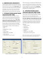
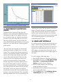
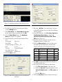
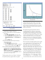
Saw Engineering and Troubleshooting Software (SETS)
USER’S MANUAL
for Band and Circular Saws
Developed by:
Department of Forest Products
Forest and Wildlife Research Center
Mississippi State University
The Forest and Wildlife Research Center at Mississippi State University was established by the Mississippi
Legislature with the passage of the Renewable Natural Resources Research Act of 1994. The mission of
the Center is to conduct research and technical assistance programs relevant to the efficient management
and utilization of the forest, wildlife, and fisheries of the state and region, and the protection and
enhancement of the natural environment associated with these resources. FWRC scientists conduct
research in laboratories and forests administered by the University and cooperating agencies and
industries throughout the country. Research results are made available to potential users through the
University’s educational program and through Center publications such as this, which are directed as
appropriate to forest landowners and managers, manufacturers and users of forest products, leaders
of government and industry, the scientific community, and the general public. Dr. George M. Hopper is
director of the Forest and Wildlife Research Center.
Authors
Dr. Philip Steele is a professor in the department of forest products. Craig Boden is a research associate in
the department of forest products.
Acknowledgement
This research is funded by the Wood Education and Resource Center, Northeastern Area State and Private
Forestry, Forest Service, U.S. Department of Agriculture; the USDA Forest Service, State and Private Forestry,
Technology Marketing Unit; and Mississippi State University’s Forest and Wildlife Research Center. This
manual was developed in cooperation with Simonds International, Fitchburg, MA.
To Order Copies
Copies of this and other Forest and Wildlife Research Center publications are available from:
Publications Office
Forest and Wildlife Research Center
Box 9680
Mississippi State, MS 39762-9680
Please indicate author(s), title and publication number if known.
Publications are also available at the web site at www.cfr.msstate.edu
Citation
Steele, P.H., C. Boden. 2009. Saw Engineering and Troubleshooting Software (SETS) User’s Manual for Band
and Circular Saws. Forest and Wildlife Research Center, Research Bulletin, Mississippi State University. 11 pp.
Research Bulletin FP521
Forest and Wildlife Research Center
Mississippi State University
Saw Engineering and Troubleshooting Software (SETS)
USER’S MANUAL
for Band and Circular Saws
1. INTRODUCTION
Taylor et al. (1999) have developed new equations
for horsepower computation that provide a new
and simplified means to compute horsepower for
both circular and band saws. This method corrects
significant errors in past approaches.
This manual describes the functional capabilities of
the Saw Engineering and Troubleshooting (SETS)
software. SETS is a PC-based software system
designed for sawmill managers or millwrights
who wish to purchase, optimize or troubleshoot
their circular or band saws. This manual provides
information on the background for the software and
a tutorial. The tutorial will prompt for information that
sawmill staff will be able to input without engineering
training. Saw designs for new sawing machines, and
optimizing and troubleshooting of current saws will
be provided by the SETS software.
The SETS software uses both Suchland’s equations to
draw a performance limitations graph and Taylor’s
horsepower equations to compute the maximum
required horsepower for the specific circular or band
saw defined by user-supplied saw characteristic data.
Thus, SETS allows sawmill managers unfamiliar
with saw engineering mechanics to determine
whether their saw is being operated within its design
limitations and to design, optimize, and troubleshoot
their saws for best performance. Use of the SETS
software will reduce the need for mechanical
engineering specialists to perform these tasks.
Saw mechanics engineering for the purpose of
purchasing, optimizing or troubleshooting saws
is a difficult task for which few sawmill managers
or millwrights have training or easily-applied
tools. The interaction of the following important
variables are very complex: hook, rake and
clearance angles; bite per tooth; material feed
speed; tooth speed; side clearance; depth of cut;
and horsepower requirements. Researchers such
as Suchsland (Undated), Lunstrum (1985) and
Taylor et al. (1999) have attempted to simplify the
analysis of the interaction of these variables to allow
sawmill personnel to rationally design, optimize
and troubleshoot their saws. However, software to
allow users to apply the required complex equations
describing saw performance without an engineering
background has been unavailable until now.
Always follow manufacturer’s instructions and
warnings, maintain appropriate safety guarding and
protocols, and utilize appropraite personal protective
equipment. Mississippi State University assumes no
liability for the content of this publication or for action
taken based on the content herein.
2. SYSTEM REQUIREMENTS
The minimum system requirements for installing and
running SETS are:
• PC with a Pentium II 450 MHz processor (Pentium
III 667+ MHz processor recommended).
• SETS can be installed on the following operating
systems: Microsoft Windows® 2000 Professional,
Windows 2000 Server, Windows XP Professional,
Windows XP Home Edition, Windows Server
2003, or Windows Vista.
• Minimum RAM requirements: 96 MB for Windows
2000 Professional; 192 MB for Windows 2000
Server; 160 MB for Windows XP Professional; 96
MB for Windows XP Home Edition; 160 MB for
Windows Server 2003 (256 MB for all operating
systems recommended).
• 20 MB of available hard-disk space on the
installation drive.
Suchland’s equations allow development of a
performance limitations graph that provides the
minimum and maximum feed speed constraints for a
saw operating at gullet capacity. These constraints are
as specific to each saw as fingerprints are to humans.
If a saw’s maximum feed speed is exceeded, the
saw teeth will be over loaded resulting in potential,
or real, damage; if saw speed falls below minimum
feed speed, sawdust will be smaller than the side
clearance and will spill onto the saw face resulting in
friction and creation of destabilizing heat in the saw
body.
-1-
4. THE SETS MAIN FORM
• CD-ROM or DVD-ROM drive.
• Super VGA (1024 x 768) or higher resolution
display with 256 colors.
• Microsoft Mouse or compatible pointing device.
SETS is written in Microsoft® Visual Basic® .NET,
version 2003 (Microsoft Corp. 2003).
The SETS software consists of a main form (Figure 1)
used for creating a new saw file, opening an existing
saw file, closing a saw file, and saving and printing
input and output data. The main form’s menu bar
consists of a File menu that contains the following
choices:
• New – Creates a new saw file.
• Open – Opens an existing saw file.
• Close – Closes the currently opened saw file.
• Save Input – Saves the input data of the current
saw under the current input file name.
• Save Input As – Opens the Save As dialog box
allowing the user to save the input data of the
current saw under a specified file name.
• Save Results – Opens the Save As dialog box
allowing the user to save the output results of the
current saw under a specified file name.
• Print – Prints the input data and the output results
of the current saw.
• Exit – Closes the SETS software.
3. INSTALLING AND RUNNING SETS
SETS must be installed and run on your computer’s
hard drive. The program will not run directly from the
installation CD. To install SETS, perform the following
steps:
1. Begin at the Windows desktop.
2. Insert the SETS installation CD into your CD-ROM
or DVD-ROM drive.
3. If the installation program does not start
automatically, follow these steps:
a. Click the Start button on the taskbar and then
click the Run… command appearing on the
Start menu. The Run dialog box appears.
b. Type E:\SETUP in the Open textbox of the
Run dialog box. (If your CD-ROM or DVDROM drive is designated by a letter other than
E, substitute that letter for E.)
c. Click the Ok button on the Run dialog box.
4. Follow the on-screen instructions provided by the
SETS installation program.
5. CREATING A NEW SAW FILE
The SETS software allows you to create and maintain
as many individual saw files as desired. To create a
new saw file, choose File, New on the menu bar.
Under the File, New menu option, a submenu
appears (Figure 2) consisting of the following three
menu choices:
• Design Band Saw
• Optimize-Troubleshoot Band Saw
• Optimize-Troubleshoot Circular Saw
To run SETS, perform the following steps:
1. Click the Start button on the taskbar.
2. Point to All Programs.
3. Point to the SETS folder icon appearing in the All
Programs list, and then click the SETS.exe icon.
4. Alternatively, you can double-click the SETS
shortcut icon on your Windows desktop.
Select one of the above three choices and SETS will
display the appropriate data input form(s). You can
then save the new saw file to your computer’s hard
drive at any time by clicking the Save Input or the
Save Input As menu choice under the File menu.
-2-
Figure 1. SETS main form
Figure 2. File, New submenu.
6. OPENING A PREVIOUSLY SAVED
SAW FILE
7. SAVING DATA AND RESULTS
Saving data in the SETS software consists of saving
either the input data describing your saw or the
output results describing your saw’s performance
limitations. Input saw data are saved in SETS using a
.sets file extension, while the output results are saved
using the .txt file extension.
To open a saw file that was previously saved in the
SETS software, follow these steps:
1. Click File, Open on the menu bar to display the
Open dialog box (Figure 3).
2. Use the Look in drop-down list on the Open
dialog box to go to the folder containing the
saw file and select the file from the files list.
Alternatively, you can type the file path and file
name in the File name text box of the Open
dialog box.
3. Make sure the file name appearing in the File
name text box has a .sets extension.
4. Click the Open button.
You can save the input saw data to your computer’s
hard drive at any time by clicking either the Save
Input or the Save Input As menu choice under the
File menu. Clicking the Save Input menu choice
saves the input data appearing in the SETS saw
data form under the current input file name (if one
exists). If an input file name has not been given for
the current input data, the Save As dialog box will
appear allowing you to enter a file name and save
the data. Clicking the Save Input As menu choice
automatically opens the Save As dialog box allowing
you to save the current input data using either a file
name other than the current input file name or the
current input file name itself.
The contents of the saw file will be loaded into the
SETS software, and you may start entering, editing, or
deleting the input data.
Once the output results data for the current saw have
been generated and appear on the SETS main form,
they can be saved to your computer’s hard drive by
clicking the Save Results menu choice under the
File menu. Clicking the Save Results menu choice
opens the Save As dialog box allowing you to enter
a file name for the output results and save the results.
Figure 3. Open dialog box.
-3-
8. PRINTING DATA AND RESULTS
When entering data in the Band Saw Data Entry form,
you can use the Tab key, the Enter key, or the mouse
pointer to navigate from one text box to another. After
entering data for all variables, click the Calculate
button and SETS will generate the output results and
the performance limitations graph.
The SETS software allows you to print both input saw
data and output results to a local printer or a network
printer. To print to a printer, choose File, Print on the
menu bar. If the output results have been generated
and appear on the screen, both input and output
data will be printed. If the output results have not
been generated, only the input data will be printed.
10. OPTIMIZE-TROUBLESHOOT
CIRCULAR SAW DATA ENTRY FORM
9. OPTIMIZE-TROUBLESHOOT BAND
SAW DATA ENTRY FORM
The Circular Saw Data Entry form (Figure 5) allows
users to enter circular saw data describing a specific
large circular saw and to calculate the saw’s
performance output results. To display this form click
File, New, Optimize-Troubleshoot Circular Saw
on the menu bar. This form consists of text boxes that
prompt you to enter values of various characteristic
variables that describe your particular circular saw
and cutting practices. These variables include the
following:
• Number of teeth
• Gullet area
• Plate thickness
• Saw diameter
• Saw kerf
• Rotations per minute (RPM)
• Wood species or specific gravity
When entering data in the Circular Saw Data Entry
form, you can use the Tab key, the Enter key, or
The Band Saw Data Entry form (Figure 4) allows
users to enter band saw data describing a specific
band saw and to calculate the saw’s performance
output results. To display this form click File, New,
Optimize-Troubleshoot Band Saw on the menu
bar. This form consists of text boxes that prompt you
to enter values of various characteristic variables
that describe your particular band saw and cutting
practices. These variables include the following:
• Gullet area
• Pitch
• Plate thickness / gauge
• Saw kerf
• Surface speed
• Rotations per minute (RPM)
• Wheel diameter
• Wood species or specific gravity
Figure 4. Band Saw Data Entry form.
Figure 5. Circular Saw Data Entry form.
-4-
Figure 6. Feed Speeds and Depth of Cut Observations
form.
the mouse pointer to navigate from one text box to
another. After entering data for all variables, click the
Calculate button and SETS will generate the output
results and the performance limitations graph.
11. FEED SPEEDS AND DEPTH OF
CUT OBSERVATIONS FORM
Figure 7. Performance Limitations Results form.
The Feed Speeds and Depth of Cut Observations
form (Figure 6) allows the user to enter data to
calculate the current feed speeds in a particular mill.
This form contains a data table that prompts the user
for data values of up to fifteen observations. These
data values consist of the following:
• Workpiece length (ft.)
• Depth of cut (in.)
• Seconds
the following output data describing the acceptable
operating range for the saw at gullet capacity:
• Saw speed (ft/min)
• Minimum tooth bite (in)
• Maximum tooth bite (in)
• Minimum feed speed (ft/min)
• Maximum feed speed (ft/min)
• Minimum depth of cut (in)
• Maximum depth of cut (in)
• Maximum horsepower
Feed speeds will be computed based on the above
values. Each feed speed along with its corresponding
depth of cut will be plotted on the performance
limitations graph (Section 13).
This form also tabulates the feed speed and tooth bite
at gullet capacity for a depth of cut ranging from 6
inches to 30 inches. This tabulation indicates whether
the feed speed and corresponding tooth bite are
within the acceptable operating range for the saw.
12. PERFORMANCE LIMITATIONS
RESULTS FORM
This form also displays the data entered in the Feed
Speeds and Depth of Cut Observations form (Section
11) and shows the corresponding feed speed for each
observation.
The Performance Limitations Results form (Figure 7)
displays numerical results describing the optimum
cutting conditions for the saw defined by the usersupplied characteristic saw data. This form displays
-5-
Figure 9. Armstrong VariDesign Deluxe main form.
Figure 8. Performance Limitations Graph.
13. PERFORMANCE LIMITATIONS
GRAPH
a portion of the curve. The blue portion of the curve
shown in Figure 8 indicates this acceptable operating
range. The horizontal and vertical lines extending
from the y-axis and the x-axis to the curve indicate,
respectively, the minimum and maximum feed speeds
and corresponding depths of cut that define the
acceptable operating range.
The Performance Limitations Graph (Figure 8)
displays a curve indicating the relationship between
feed speed and depth of cut at gullet capacity for
the saw defined by the user-supplied characteristic
saw data. At any point along the curve, the saw is
operating at gullet capacity. Any point above the
curve would exceed the gullet capacity and any point
below the curve means the saw is operating below
gullet capacity.
14. BAND SAW TUTORIAL A
This section provides a tutorial intended to help users
design a band saw using the Armstrong Varidesign
Deluxe software (2003). This tutorial also shows how
to optimize or troubleshoot the band saw using the
SETS software. An explanation of the results and an
interpretation of the performance limitations graph is
also given.
As can be seen from the graph, the relationship
between feed speed and depth of cut is inversely
related. Thus, cutting smaller diameter logs would
require an increased feed speed to maintain gullet
capacity and cutting larger diameter logs would
require a decreased feed speed. There are limits,
however, on the size of logs that can be cut for
a given saw at gullet capacity. Cutting smaller
diameter logs would increase the tooth bite due to
the increased feed speed, and hence, subject the
saw teeth to excessive strain. Cutting larger diameter
logs would decrease the tooth bite due to the lower
feed speeds, and hence, produce very fine saw
dust particles that may spill from the gullets into the
spaces on each side of the blade. Thus, acceptable
operating conditions for a saw are restricted to only
To run this tutorial, follow these steps:
1. Start the SETS software as described in Section 3.
2. On the SETS main form, click File, New, Design
Band Saw. The Armstrong VariDesign
Deluxe main form (Figure 9) appears.
3. Maximize both windows of the Armstrong
Varidesign Deluxe main form.
4. Scroll down the list of standard saws and click on
the saw named 380-Q-U.
5. Click the Load button. The VariDesign Deluxe
Tooth Designer form (Figure 10) appears.
-6-
Figure 10. VariDesign Deluxe Tooth Designer form.
Figure 11. VariDesign Deluxe Bandsaw Data form.
6. To modify the 380-Q-U standard tooth design,
click the Modify button.
7. Enter 380-Q-Ua in the Tooth Name text box
for the name of the new tooth and click Ok.
8. Click the Band Data button. The Bandsaw
Data form (Figure 11) appears.
9. Enter the following data into the Bandsaw Data
form:
Saw Length:
38 ft. 0 in.
Saw Width:
10 in.
Thickness/gauge: 0.072in. / 15
Kerf:
0.16 in.
Tip Type:
Swaged&Shaped
Avg. depth of cut: 18 in.
Surface Speed: 9800 ft/min
10.Click the Save button.
11.Press the <Alt-Tab> key combination, to return
to the SETS software. Do not close the VariDesign
Deluxe program.
12.In the SETS software, click File, New, OptimizeTroubleshoot Band Saw to display the
Optimize-Troubleshoot Band Saw Data
Entry form (Figure 4).
13.Enter the data for the band saw that was just
designed as shown in Figure 12.
14.Click the Observations button and then enter
the following five observations into the Feed
Speed and Depth of Cut Observations form:
Obs.
No.
1
2
3
4
5
Workpiece
Length (ft.)
15.5
16
12
14
15
Depth of
cut (in.)
12
11
15
16
14
Sec.
5
3
2.8
2.5
2.77
15.Click Ok to close the Feed Speed and Depth of
Cut Observations form.
16.Save the input data by following these steps:
a. Click File, Save Input on the menu bar.
b. When the Save As dialog box appears, enter
Tutorial-Band A.sets in the File name text
box.
c. Click the Ok button.
17.Click the Calculate button to display the output
Figure 12. Band Saw Data entry form for band saw
tutorial A.
-7-
Figure 14. Performance Limitations Graph for band
saw tutorial A.
capacity. Along this portion of the curve, the log
diameters are restricted to a range of 13.0 inches
to 20.4 inches. For log diameters within this range,
Figure 13 shows the corresponding feed speeds and
tooth bite dimensions.
Figure 13. Performance Limitations Results for band
saw tutorial A.
The region of the graph lying between the two
horizontal dotted lines in Figure 14 indicates the
acceptable operating conditions for the saw. Within
this region the minimum feed speed is 215.6 ft/min
and the maximum feed speed is 352.8 ft/min. If feed
speeds exceed 352.8 ft/min, the saw teeth will be
subject to excessive strain. If feed speeds fall below
215.6 ft/min, saw dust will spill from the gullets and
cause the saw rim to overheat.
results shown in Figures 13 and 14.
18.Save the output results to a text file by following
these steps:
a. Click File, Save Results on the menu bar.
b. When the Save As dialog box appears, enter
Tutorial-Band A.txt in the File name text
box.
c. Click the Ok button.
19.Print the input data and the output results by
following these steps:
a. Click File, Print on the menu bar.
b. When the Print dialog box appears, select the
correct printer and then click the Ok button.
20.If you want to modify the saw input data and
run the analysis on the modified data, click the
Modify button on the Optimize-Troubleshoot
Band Saw Data Entry form. Change the saw
data as desired and click the Calculate button to
generate the new output results.
The five dark blue rectangles appearing on the graph
are the plotted depth of cut-feed speed values. The
feed speed values were computed based on the
observation data entered in the Feed Speeds and
Depth of Cut Observations form (Figure 6). As can be
seen from the graph, there is one depth of cut and
feed speed value (depth of cut = 14 in./feed speed
= 325 ft/min) lying directly on the blue portion of
the curve, indicating that the saw was operating at
gullet capacity for that observation. There are two
points (depth of cut = 15 in./feed speed = 257 ft/
min and depth of cut = 11 in./feed speed = 320 ft/
min) that lie below the curve but within the minimum
The blue portion of the curve in Figure 14 indicates
the optimal operating range for the saw at gullet
-8-
and maximum feed speed range, indicating that the
saw was operating within the acceptable feed speed
range, but the gullet capacity was underutilized for
these two observations. There is one point (depth of
cut = 16 in./feed speed = 336 ft/min) that lies above
the curve, indicating that the saw exceeded gullet
capacity for that observation. The last point (depth of
cut = 12 in./feed speed = 186 ft/min) lies below the
minimum feed speed, indicating that saw dust would
spill out of the gullets for this feed speed-depth of cut
combination.
As can be seen in Figure 13, the maximum required
horsepower at the maximum feed speed of 352.8
ft/min is 168.2. This horsepower value is based on
the horsepower equations given in Example 5 of
Taylor, et. al. (1999). These horsepower equations
use a range of species-specific wood densities and
tooth bites to calculate the required horsepower. The
SETS software adds a 20% risk factor to the resulting
horsepower derived from these equations.
Figure 15. Performance Limitations Results for band
saw tutorial B.
15. BAND SAW TUTORIAL B
This section provides a second band saw tutorial
intended to help users optimize or troubleshoot a
band saw using the SETS software. An explanation of
the results and an interpretation of the performance
limitations graph is given.
4. Click the Observations button and then enter
the following five observations into the Feed
Speed and Depth of Cut Observations form:
Obs.
No.
1
2
3
4
5
To run this tutorial, follow these steps:
1. Start the SETS software as described in Section 3.
2. Click File, New, Optimize-Troubleshoot
Band Saw.
3. In the Optimize-Troubleshoot Band Saw
Data Entry form, enter the following data
values:
Gullet area:
1 in.2
Pitch:
2 in.
Plate thickness: 0.072 in.
Saw kerf:
0.165 in.
RPM:
531
Wheel diameter:
72 in.
Species:
Pine, Loblolly
Workpiece
Length (ft.)
16
16
16
16
16
Depth of
cut (in.)
12
15
14
12
13
Sec.
2.82
3.2
3.92
3.56
3.84
5. Click Ok to close the Feed Speed and Depth of
Cut Observations form.
6. Click the Calculate button to display the output
results shown in Figures 15 and 16.
The region between the two horizontal dotted lines in
Figure 16 indicates acceptable operating conditions.
The minimum and maximum feed speeds are 232.7
ft/min and 360.3 ft/min, respectively. The blue
-9-
3. In the Optimize-Troubleshoot Circular Saw
Data Entry form, enter the following data
values:
Number of teeth:
50
Gullet area:
2.0 in.2
Plate thickness:
0.165 in.
Saw diameter:
54 in.
Saw kerf:
0.281 in.
RPM:
637
Species:
Pine, Loblolly
4. Click the Observations button and then enter
the following five observations into the Feed
Speed and Depth of Cut Observations form:
Figure 16. Performance Limitations Graph for band
saw tutorial B.
Obs.
No.
portion of the curve indicates the optimal operating
range for the saw at gullet capacity. Along this portion
of the curve, the log diameters are restricted to a
range of 11.2 inches to 16.6 inches.
Of the five observation points, three are below the
curve, but lie in the acceptable feed speed range,
indicating that the gullet capacity was underutilized
for those observations. The other two are above
the curve, indicating that the saw exceeded gullet
capacity for those observations.
Workpiece Length
(ft.)
Depth of cut
(in.)
Sec.
1
14
16
5.09
2
12
18
4.5
3
14
20
5.09
4
16
16
4.36
5
12
15
3.79
5. Click Ok to close the Feed Speed and Depth of
Cut Observations form.
6. Click the Calculate button to display the output
results shown in Figures 17 and 18.
The blue portion of the curve in Figure 18 indicates
the optimal operating range for the saw at gullet
capacity. For this saw the log diameters are restricted
to a range of 14.2 inches to 24.3 inches.
The maximum required horsepower at the maximum
feed speed of 360.3 ft/min is 152.5.
16. CIRCULAR SAW TUTORIAL
The region of the graph lying between the two
horizontal dotted lines in Figure 18 indicates the
acceptable operating conditions for the saw. Within
this region the minimum feed speed is 174.5 ft/min
and the maximum feed speed is 331.8 ft/min. If feed
speeds exceed 331.8 ft/min, the saw teeth will be
subject to excessive strain. If feed speeds fall below
174.5 ft/min, saw dust will spill from the gullets and
cause the saw rim to overheat.
This section provides a tutorial intended to help users
optimize or troubleshoot a typical large diameter
circular saw. This tutorial covers data entry, results
generation, and an interpretation of the performance
limitations graph.
To run the circular saw tutorial, follow these steps:
1. Start the SETS software as described in Section 3.
2. Click File, New, Optimize-Troubleshoot
Circular Saw.
-10-
Figure 18. Performance Limitations Graph for circular
saw tutorial.
Figure 17. Performance Limitations Results for circular
saw tutorial.
Of the five observation points, two lie in the
acceptable feed speed range, but are below the
characteristic curve, indicating that the gullet capacity
was underutilized for these observations. The other
three points lie below the minimum feed speed,
indicating that saw dust would spill out of the gullets
for these feed speed-depth of cut combinations.
The maximum required horsepower at a feed speed
of 331.8 ft/min is 207.6.
-11-
Literature Cited
Armstrong Mfg. Co. 2003. Varidesign Deluxe, Version 1.305.9. Portland, OR.
Lunstrum, S. J. 1985. Balanced saw performance. Tech. Rep. No. 12. USDA Forest Service, Forest Products
Laboratory, Madison, WI.17 p.
Microsoft Corporation. 2003. Microsoft Visual Basic .NET, Version 2003. Redmond, WA.
Suchsland, O. Undated. Operating characteristics and performance limitations of circular and band saws. Dept.
of Forestry, Cooperative Extension Service, Michigan State University. Ext. Bull. E-1353. 6 p.
Taylor, J., A. Gingras, J. White, R. Niessen and D. Gagne. 1999. A report summary of “Power requirements for
sawing and chipping”. In: Proc. of Saw Tech ’99 International Conference. Nov. 4-5, Seattle, WA. pp 75-84.
-12-
Feed Speed and Depth of Cut
Data Sheet
Sawing machine:
___________________
Date:
___________________
Observation
No.
Workpiece
Length (ft.)
Depth of
Cut (in.)
1
2
3
4
5
6
7
8
9
10
11
12
13
14
15
-13-
Seconds
Feed Speed and Depth of Cut
Data Sheet
Sawing machine:
___________________
Date:
___________________
Observation
No.
Workpiece
Length (ft.)
Depth of
Cut (in.)
1
2
3
4
5
6
7
8
9
10
11
12
13
14
15
-14-
Seconds
Discrimination based upon race, color, religion, sex, national origin, age, disability, or veteran’s status is a violation of federal and state law and MSU
policy and will not be tolerated. Discrimination based upon sexual orientation or group affiliation is a violation of MSU policy and will not be tolerated.