1
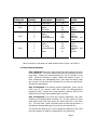
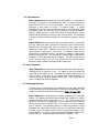
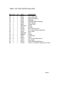
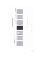
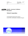
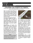
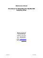
Maintenance Manual
Procedures for Rebuilding the PQ100/200
Sampling Pump
BGI Incorporated
58 Guinan Street
Waltham, MA 02451
Tel: 781.891.9380
Fax: 781.891.8151
Email: [email protected]
Web Site: www.bgiusa.com
Version 3.1
June 2009
Table of Contents
Section
Number
Topic
Page
1.0
Introduction
1
2.0
When to Rebuild
1
3.0
Disassembly and Inspection
1
3.1
Motor/Bearing Assembly
2
3.2
Valve Removal
3
3.3
Valve Inspection
3
3.4
Diaphragm Removal
3
3.5
Diaphragm Inspection
4
4.0
Re-assembly
4
4.1
Diaphragm and Yoke Assembly
4
4.2
Valve Assembly
5
4.3
Diaphragm Setting
6
4.4
Motor Installation
6
5.0
Final Procedure
7
6.0
Disclaimer
7
Table 1
8
Figure 1
9
Figure 2
10
Revision History
11
1.0 Introduction
The pump used in the BGI PQ100 and PQ200 air samplers is of BGI design and manufacture.
The only items not of BGI manufacture are the motor and bearing for the eccentric. The
basic design is a double diaphragm, steel reed valve, scotch yoke. This is a time-honored
design. BGI’s contributions centered upon developing the most efficient unit for its intended
application. Two unique BGI developments are the complete internalization of all flow
transfer passages for noise minimization and the development of the technique for the preconvoluting flat diaphragms for maximum life and efficiency.
2.0 When to Rebuild
The full question is when to rebuild and how many items to replace. There are two simple
answers.
1. Rebuild the pump when it has ceased to function.
2. Rebuild when sufficient, in service hours have elapsed, to indicate that certain
components are nearing the end of their effective service lifetime. Because of the
variable use to which a pump is subjected, it is hard to quote a fixed number of
hours for preventative maintenance. Experience has now shown, that when the
pump is utilized for normal EPA type sampling, i.e. 16.7 Lpm at 30-50cm of H2O
pressure drop, eight to nine thousand hours may be readily anticipated. This
amounts to one year of continuous operation. Under idealized conditions, we have
run the pump at 16.7 Lpm against 50cm of H2O for 18 months. The mode of failure
was pump brush wear (brushes are non-replaceable). Bear in mind, given EPA
sampling protocols 8-9000 hours is 2 years of every other day sampling, 3 years of
every third day and 6 years of every sixth day!
The following chart is a guide to preventative maintenance for absolute reliability.
Replace
Replace
Replace
Replace
Motor:
9000 Hours
Diaphragms:
9000 Hours
Eccentric and Bearing: 14000 Hours
Valves
14000 Hours
Using the equipment for non EPA designated sampling at high flow rates and/or pressure
drops may significantly abbreviate the above figures and it would not be imprudent to
perform a complete rebuild at 5000 hours.
It is always recommended that, when practical, pumps be factory rebuilt inasmuch as factory
service will carry a one year warranty and client field service cannot.
3.0 Disassembly and Inspection
All of the component parts of the pump are shown in Figure one and described in the parts
list, Table One. Four levels of repair/rebuild kit are made available. Other than the parts
listed in the kits, it is not anticipated that any other components will be required except
through physical damage or loss.
Rebuild Kits:
Page 1
Catalog No.
X017
X014
X015
X016
Quantity
Description
Detail No.
2
Diaphragms
2
2
8
2
2
8
1
Diaphragms
Valves
“O” Rings
Diaphragms
Valves
“O” Rings
Mounted Bearing
38
50
48
38
50
48
42, 43
38
2
2
8
1
Diaphragms
Valves
“O” Rings
Mounted Bearing
38
50
48
42, 43
1
Motor
47
Part No.
A2187
A2187
B1408
BUNA010
A2187
B1408
BUNA010
DDRI-6632, and
A1294
A2187
B1408
BUNA010
DDRI-6632, and
A1294
PQ Motor
Note: In working on the pump unit, detail numbers refer to Figure 1 and Table 1.
3.1 Motor/Bearing Assembly
Step 1-Required Remove two sheet metal screws (88) securing the motor
to the pump body. The motor assembly may now be pulled away from the
pump body. Inspect the eccentric/bearing (42, 43) for looseness on the
shaft. Inspect the bearing for smooth rotation and absence of play. If
these components are undamaged/unworn, then wipe the bearing clean
with a fresh, lint free cloth and re-lubricate all over with any light grease.
Set aside for reassembling.
Step 2-If Required If the bearing requires replacement, loosen the set
screw (44) on the eccentric shaft and remove the bearing/eccentric
assembly (42,43). Replace with a new assembly, pushing it firmly on the
shaft as far as it will go, before tightening the set screw.
Step 2-If Required If the motor also requires replacement, then, after
removing the bearing/eccentric assembly (42, 43) also remove the three
motor plate screws (45) which secure the motor plate (46) to the motor
(47). The new motor, which is furnished with the cable and connector, is
assembled to the plate utilizing the three screws just removed (45).
The eccentric and bearing (42, 43) are replaced as described in step 2 and
the motor assembly is ready for re-attachment to the pump body.
Page 2
3.2 Valve Removal
Step 4-Required Before beginning valve disassembly, it is important to
note that it is possible to mis-assemble this section so that the pump will
fight itself and little or no air will be pumped. This can be avoided if the
alignment of parts shown in Figure 1 is followed exactly. A simpler
procedure is to scribe a line, free hand, across the entire face of the pump
body marking parts 35, 36 and 40. By this procedure, it will be impossible to
commit a misalignment error if the scribe marks are exactly aligned. Do not
scribe the face containing the motor nor the mounting studs. This procedure
is commonly used in machine assembly and is known as applying a witness
mark.
Step 5-Required Starting on either side of the pump remove 4 screws (86)
from the valve upper plate (35) and lift off and set aside. The valve plate
alignment pins (locating pins) (49) are pressed into the plate. Do not
attempt to remove them. Carefully remove the valve (50) which may be
lightly adhered to the upper or lower plate. Be extremely careful as this
component is only 0.001 inch thick. Set aside for inspection. Next remove
the valve lower plate (36). This component is usually a tight fit and a strong
thumbnail or thin knife blade may be required. Set aside, taking care to
remove and set aside the 4 “O” rings which have now become visible.
Repeat the same procedure on the other side of the pump.
3.3 Valve Inspection
Step 6-Required All metal parts now visible should be bright and clean,
completely free of corrosion or dirt. The leaves of the valve should be
nearly flat or only slightly curved. The edges of the leaves should be free of
chips or cracks. If the valves are not perfect, they should be replaced. If
they are dirty they should be carefully wiped clean. If the valves become
bent or creased, they must be replaced.
3.4 Diaphragm Removal
In August 2001 a new diaphragm was introduced. It can be redialy identified
by its orange/red color and convolutions. If you have this diaphragm in your
pump or are about to install them utilize sections 3.5A,4.1A and 4.3A.
Step 7-Required The diaphragms are removed by grasping the diaphragm
retainer (37) between the thumb and forefinger and rotating in a counter
clockwise direction when looking down on it. This part is a white disk
situated in the center of the diaphragm. The other hand is used to grasp the
same component on the opposite side. In this manner one of the retainers
may be removed. The remaining retainer is removed by inserting a finger
throughout the bearing hole and forcing the yoke (41) against an inside wall.
This will prevent its rotation and permit the removal (unscrewing) of the
second retainer. You will now have removed both diaphragm retainers (37)
and the yoke (41). Set these components aside for inspection. The
Page 3
diaphragms may now be pulled from their recesses. If the diaphragms
became dislodged and removed with the retainers, no harm has been done.
Lay out all parts for inspection.
3.5 Diaphragm Inspection
Step 8-Required A new diaphragm is quite flat. A used one takes on a
curved shape with use which is both normal and desirable. All current
production utilizes a highly specialized material, which contains an imbedded,
woven nylon cloth. This material yields extremely long life and superior
performance. All other diaphragms should be replaced.
To inspect the condition of a diaphragm, grasp it across its diameter and
pull in opposite directions. If any cracks in the surface are observed the
diaphragm must be discarded.
3.5A Diaphragm Inspection (introduced Aug 2001)
Step 8-Required All current production utilizes a highly specialized
material, which contains an imbedded, woven Nomex cloth. This material
yields extremely long life and superior performance. All other diaphragms
should be replaced.
To inspect the condition of a diaphragm, grasp it across its diameter and
pull in opposite directions. If any cracks in the surface are observed the
diaphragm must be discarded.
4.0 Re-assembly
4.1 Diaphragm and Yoke Assembly
Step 9-Required If a new diaphragm is being installed it does not have a
preferential side. If a used diaphragm is being re-installed it will be curved. When
properly inserted you will be looking down into a cup shape. Insert the diaphragm
retainer (37) into the diaphragm (38) and slide the diaphragm retainer bushing (39)
over the diaphragm retainer shaft. Seize the follower yoke with a pair of long nose
pliers and insert it through the drive hole in the pump housing (40). Align the
threaded hole in the yoke, such that the diaphragm assembly may be inserted
through its guide hole in the pump body and screwed into the yoke. Grasp the
diaphragm retainer between the thumb and forefinger and rotate clockwise two
turns. The diaphragm will be lying on top of the pump body. Leave it that way, for
the moment. Discard the long nose pliers. Prepare the opposite diaphragm
assembly and screw it into the yoke two turns, holding each assembly between the
thumb and forefinger of each hand. The diaphragms may now be inserted into their
recess. The edges of the disks are to be tucked into the recess provided in the
Page 4
pump body (40). Looking through the drive hole align the yoke, by eye so that you
are looking into the bearing drive recess and align it such that it will receive the
eccentric bearing and is parallel to the pump sides and square to the face. Now
complete tightening the loose diaphragm retainers to the yoke and check alignment.
Install the 8 “O” rings (48) into the body and set the assembly aside.
4.1A Diaphragm and Yoke Assembly (introduced Aug 2001)
Step 9-Required If a new or used convoluted diaphragm is being installed has a
preferential side. If a used diaphragm is being re-installed it will be curved. Insert
the diaphragm retainer (37) into the diaphragm (38) and slide the diaphragm
retainer bushing (39) over the diaphragm retainer shaft. Reference Figure 1 inset
for the direction of the convolution. Seize the follower yoke with a pair of long nose
pliers and insert it through the drive hole in the pump housing (40). Align the
threaded hole in the yoke, such that the diaphragm assembly may be inserted
through its guide hole in the pump body and screwed into the yoke. Grasp the
diaphragm retainer between the thumb and forefinger and rotate clockwise two
turns. The diaphragm will be lying on top of the pump body. Leave it that way, for
the moment. Discard the long nose pliers. Prepare the opposite diaphragm
assembly and screw it into the yoke two turns, holding each assembly between the
thumb and forefinger of each hand. The diaphragms may now be inserted into their
recess. The edges of the disks are to be tucked into the recess provided in the
pump body (40). Looking through the drive hole align the yoke, by eye so that you
are looking into the bearing drive recess and align it such that it will receive the
eccentric bearing and is parallel to the pump sides and square to the face. Now
complete tightening the loose diaphragm retainers to the yoke and check alignment.
Install the 8 “O” rings (48) into the body and set the assembly aside.
4.2 Valve Assembly
Step 10-Required Lay the valve upper plate (35) outside face down on the bench.
Lay the valve upper plate (50) onto the surface using the guide pins for alignment.
If it is a used valve and the fingers have taken a curve, be certain that the curve is
towards the round holes in the valve plate. Lay the flat surface of the valve lower
plate (36) on top of the valve using the guide pin holes for alignment. Check to see
that the witness mark, which you previously scribed onto these parts is aligned. If
not, raise the lower valve plate and re-align. Place the valve assembly onto the
pump body. Press it home into the diaphragm recess and align the witness marks on
the valve plates with those on the body. Install the four securing screws (86) but do
not fully tighten.
Assemble and install the other valve components to the body in the same manner.
Page 5
4.3 Diaphragm Setting
This procedure must be successfully accomplished or the pump performance will be
diminished and high current draw will ensue.
Step 11-Required Place the forefinger into the center of the yoke and push it
towards a diaphragm until it contacts the side of the recess. Tighten the 4 valve
plate screws (86) on the side opposite to the one the yoke is being held against.
This procedure has pulled down and pre-convoluted the diaphragm, which is now
secure. Follow the same procedure for the other side. Your should now be able to
move the yoke to either end of its stroke and easily contact the yoke to the pump
body. If there is any springiness or resistance at the end of the stroke, repeat the
procedure until success is achieved. When installing new diaphragms, it will be
necessary to perform this operation two to three times.
Note that after tightening the four screws (86), simply loosening them may not
release the clamping pressure on the diaphragm. In this case, draw the valve
assembly back to relieve the pressure and then push the yoke to the opposite side.
4.3A Diaphragm Setting (introduced Aug 2001)
This procedure must be successfully accomplished or the pump performance will be
diminished and high current draw will ensue.
Step 11-Required The diaphragms will naturally center themselves so that the
yoke is observed to be in the center of the drive hole. All 8 of the valve plate screws
(86) may now be tightened.
4.4 Motor Installation
Step 12-Required Place the motor assembly into the hole in the pump body and
rotate it until the bearing engages the opening in the yoke (41). The motor plate
will not lie flat to the body unless the bearing is engaged in the yoke. Once this is
accomplished, align the two screw holes in the motor plate to the screw holes in the
pump body. Re-install the two motor plate securing screws (88). Before fully
tightening the screws, ensure that you observe an equal strip of the black delrin
pump body around all four sides of the motor plate. In other words, centralize the
motor plate on the pump body prior to final screw tightening.
Page 6
5.0 Final Procedure
Re-install the pump in the instrument and set up a run. When the pump comes on, ensure
that it is drawing air through the instrument. If not, then the intake and exhaust pipes have
been reversed. Place the suction hose onto the suction side of the pump and proceed to
verify proper operation.
If witness marks were not properly scribed onto the pump body prior to disassembly, or if
several pumps have been disassembled or through malfortune, the valve plates have been
improperly installed, refer to Figure 2. Following this figure, carefully, will permit the pump
to be reassembled with the air flow paths in the proper direction.
It is highly recommended to run a 24 hour burn in of a rebuilt pump to allow the diaphragms
to settle. The only consequence of not following this procedure is a tendency to draw 10 to
15% higher current during the first 24 hours.
When reinstalling a rebuilt pump for the first time, there may be a delay of up to 30 seconds
before the pump “turns over”. This is within normal limits but should only occur, if at all,
during the first start up. If 30 seconds has been exceeded, shut down at once. The assembly
procedures have not been correctly followed. Check, particularly, pre convoluting of the
diaphragms.
If the pump runs but there is little or no air flow, check to ensure that one of the valve
assemblies has not been reversed. If this has occurred, one side of the pump will be drawing
air whilst the other side is pushing. Essentially, the pump is fighting itself. Disassemble and
refer to Figure 2.
Recalibration of a PQ100/200 is not required after the replacement/rebuilding of a pump.
However, in following good practice it is always wise to verify flow calibration after replacing
a major component
6.0 Disclaimer
BGI accepts no responsibility for damage caused by successfully following the procedures
detailed in this manual. If in doubt, return the pump to BGI for inspection/repair. Pumps
are perfectly acceptable in a disassembled state.
Page 7
Table 1 List of PQ 100/200 Pump Parts
DET.#
35
36
37
38
39
40
41
42
43
44
45
46
47
48
49
50
86
87
88
89
QTY
2
2
2
2
2
1
1
1
1
1
3
1
1
8
4
2
8
2
2
2
FIG.
1
1
1
1
1
1
1
1
1
1
1
1
1
1
1
1
1
1
1
1
PART #
B1292
B1293
A1288
A2187
A1289
B1283
A1287
DDRI-6632
A1294
SC0105
SC0106
A1290
PQMOTOR
BUNA010
A1402
B1408
SC1014
A1403
SC1013
SC1015
DESCRIPTION
Valve Upper Plate
Valve Lower Plate
Diaphragm Retainer
Diaphragm
Diaphragm Retainer Bushing
Pump Housing
Follower Yoke
Bearing
Eccentric
M4 X 4mm Set Screw
M2.5 X 8mm Cheese Head Screw
Motor Mount
Motor
O-Rings
Locating Pins
Valves
# 8 X 1 Sheet Metal Screws
Pump Tubes
#8 X 5/8 Sheet Metal Screws
#8-32 X 11/4 Studs for Pump (PQ 200 only)
Page 8
Figure 1 – Exploded Diagram of Pump
Page 9
Page 10
Revision History
V. 1.0
Initial Composition
January 2000
V. 2.0
Revised text, added Figure 2
February 2000
V. 3.0
Updated for use with convoluted diaphragms
August 2001
V. 3.1
Updated Figure 1 to show concave side
June 2009
Page 11