1
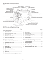
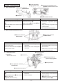
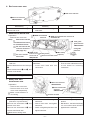
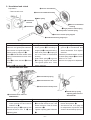
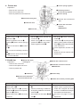
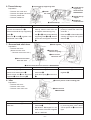
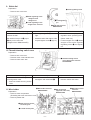
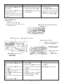
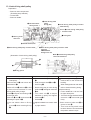
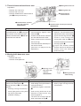
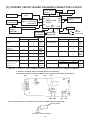
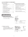
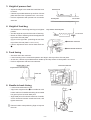
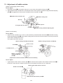
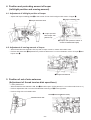
R
1-NEEDLE LOCKSTITCH SEWING MACHINE WITH
AUTOMATIC THREAD TRIMMER FOR PROFESSIONAL
TL-98E
SERVICE MANUAL
293-27707
CONTENTS
[1] SPECIFICATIONS OF TL-98E........................................................................ 1
[2] PRINCIPLE OF ELECTRIC BRAKE ............................................................... 2
[3] NAMES OF COMPONENTS ........................................................................... 3
[4] DISASSEMBLY AND ASSEMBLY ................................................................. 3
[5] PRINTED CIRCUIT BOARD DIAGRAM (CONNECTOR LAYOUT) ............. 15
[6] ADJUSTMENTS OF COMPONENTS ........................................................... 16
WARNING :
To avoid the risk of fire, electric shock, injury to persons or damage to components, especially keep the
following :
•
•
•
When disassembling, assembling or adjusting the sewing machine, remove the power plug.
When assembling, be careful about the electrical cord being caught with other components, damage
to the covered parts of the cord or miswiring.
When replacing the part(s), use the genuine part(s).
[1] Specifications of TL-98E
(1) Speed control device
Foot controller method
:
80 to 1,500 rpm
(2) Table and stand components
Main unit :
Handle
:
Portable type main unit with soft case (Case is folded in two and packed with main unit.)
One-touch type auxiliary table knee lifter is provided as standard. (Packed together)
Pull-up/down from machine main unit type
(3) General mechanism
1.
2.
3.
4.
Thread take-up
Hook
Pressing pressure adjustment
Lighting device
:
:
:
:
:
:
:
:
Slit type link thread take-up for one-touch threading
DB type horizontal full-rotary hook
Stepless adjusting screw with pressing pressure indicator method
Built in face cover
Switch : Slide type
Lamp ...... Halogen lamp
Thread guide of thread post is of tilting type and capable of one-touch
threading
One-touch action : Starting method by controller Automatic stop
when bobbin thread winding completed
ON/OFF 2-step method
By lever : 7 mm Max. by lever : 10 mm By knee lifetr : 12 mm
Disk pressure adjusting type with simplified disk pressure scale
2-step changeover by knob method (Feed dog : UP : DOWN)
:
:
Dial method ......Stepless 0 to 6 mm
Lever method ...... Feed amount conforms to that of normal feed stitch.
5. Needle thread post
:
6. Bobbin thread winder
:
7.
8.
9.
10.
Power switch
Lift of presser foot
Thread tension
Drop feed
(4) Feed mechanism
1. Feed amount adjustment
2. Reverse feed stitch
(5) Special mechanism
1. Automatic thread trimming
2.
3.
4.
5.
:
Thread trimming switch is used in common for pushbutton type and
for external foot pedal switch type.
Needle bar stop position
: Electric brake stop method
Stop by controller
: Down stop
Stop by automatic thread trimming : Up stop
Stop by bobbin winder
: Up stop
Needle up/down switch
: Switch is of pushbutton type and up/down stop by half rotation of
main shaft
Prevention of reverse setting of needle : Needle is attachable to normal direction only.
Motor protection
Overcurrent : When motor is locked for approximately one second due to sudden overload, motor power
is automatically turned OFF and returns to the ON state immediately.
Overheat
: When motor temperature has abnormally risen, motor power is turned OFF (thermal cut)
and returns to the ON state when temperature has fallen.
(6) Dimensions and weight
Main unit : 452W x 219L x 319H (mm)
Weight
: 11.3kg
(7) Power consumption
Whole sewing machine
Lamp
: 120V 1.4A/60Hz
: 12V 3W (Halogen lamp)
–1–
[2] Principle of Electric Brake
Three lead wires are drawn out from the motor. Lead wire is drwan out from the connecting point of the rotor coil
and stator coil to use the electric brake. MP detection printed circuit board asm. detects the number of slits of
the shield plate fixed on the motor shaft and is used to calculate the number of rotations of the motor and the
phase of main shaft. There are 72 pcs. of slits on the shield plate per circle. If the slit is converted into the main
shaft angle, the position can be measured (calculated) in a unit of 0.4 degrees. Comparing with the conventinal
model, the number of slits are increased and unevenness of rotation can be controllable. Principle of the
electric brake is called dynamic braking. The rotor becomes the dynamo and generates the electric power while
motor is rotating. Electric brake makes use of the fact that the brake is applied to the motor by consuming this
electric power. The higher the number of rotations becomes, the more the brake force becomes and the lower
the less.
At the time of normal rotation of motor
Brake : Off
At the time of motor brake
Brake : ON
Motor drive : ON/OFF
Motor drive : Full wave phase control
At the time of inertia stop or
normal stop of motor
Brake : OFF
Motor drive : Oscillation
Motor drive : OFF
Motor drive : Oscillation
Motor drive : OFF
: Motor drive ON
Motor drive simplified diagram
–2–
[3] Names of Components
Thread guide base
Presser spring regulator
Arm cover asm.
Thread guide No. 1
Indicating needle of
presser spring regulator
Face cover
Bobbin winder shaft
Belt cover
Handwheel
Stitch dial
Pressure indicating plate
Thread take-up thread guide
Needle up/down switch
Automatic thread trimming switch
Lamp switch
Thread take-up spring
Reverse feed stitch lever
Presser bar connection thread guide
Drop-feed knob
Lamp bulb
Hand lifter lever
Needle bar thread guide
(Hole for auxiliary table support plate)
Bed cover
Needle bar thread bracket
(Hole for auxiliary table support plate)
Bed cover rubber seat
Side cover
Throat plate asm.
Hole for knee lifter lever setting
Thread take-up spring adjusting plate
Standard presser foot asm.
[4] Disassembly/assembly
Page
Outer Components
1. Arm cover asm. ...................................... 4
2. Belt cover and motor cover .................... 4
3. Face plate asm. ...................................... 4
4. Bed cover mas. asm. .............................. 5
5. MAIN circuit board asm. ......................... 5
Function components
1. Motor asm. and transformer asm. .......... 5
2. Handwheel and clutch ............................ 6
3. Thread tensioner asm. ........................... 6
4. Presser bar ............................................. 7
5. Needle bar .............................................. 7
6. Thread take-up ....................................... 8
7. Reverse feed stitch lever ........................ 8
8. Idler ........................................................ 8
9. Stitch dial ................................................ 9
10. Automatic thread trimming switch case .. 9
Page
11.
12.
13.
14.
15.
Wire holder ............................................. 9
Knee lifter lever ..................................... 10
Hook driving shaft pulley ......................... 11
Hand lifter lever ..................................... 12
Drop-feed knob ..................................... 12
Automatic thread trimming components
1. Looper mas. asm. ................................. 13
2. Moving knife arm
installing plate mas. asm. ..................... 13
3. Thread trimming solenoid mas. asm. ... 14
4. Moving knife base mas. asm. ............... 14
–3–
6 Convex of presser
spring regulator knob
Outer Components
1. Arm cover asm.
5 Slit of presser regulating screw
4 MAIN circuit board case cover
1 Arm cover setscrew
SM5042005SN
3 Arm cover
2 Bobbin winder connector
Disassembly
Remove two setscrews of 1.
Disconnect and remove connector of
2.
Remove MAIN circuit board case
cover of 4.
Assembly
Attach case cover of 4.
Insert connector of 2.
Align convex of 6 with slit of 5 and
tighten the setscrew.
Point
™ There should be no torsion or
distorsion in presser spring
regulator.
™ Align precisely slit portion with
convex portion.
™ Do not press each lead wire.
2. Belt cover and motor cover
2 Motor cover setscrew
SM5041255SN
1 Belt cover setscrew
SM5041255SN
Disassembly
Remove four setscrews of 1 and
remove belt cover.
Remove three setscrews of 2 and
remove motor cover.
Assembly
™ Attach belt cover and tighten
setscrews.
™ Attach motor cover and tighten
setscrews.
1 Lamp connector
3. Face plate asm.
Preparation
™Remove arm cover.
Point
™ There should be no difference in
level between belt cover and front
face of frame.
™ Make motor cover come closely
contact with belt cover.
5 Face cover
4 Indicating needle of
presser spring regulator
3 Face plate asm.
2 Face plate asm. setscrew
SL5040631SE
6 Hand lifter lever spring
Disassembly
Disconnect 1 connector and remove
6.
Remove setscrews of 2 and remove
3 face plate asm.
(together with face cover).
Assembly
™ Attach face plate asm. and tighten
setscrews.
™ Insert connector.
–4–
Point
™ There should be no difference in
level around the cover when face
cover is closed.
™ 5 should not come in contact with
indicating needle of 4.
4. Bed cover mas. asm.
1 Bed cover setscrew
1 Bed cover setscrew
SM5051255SN
Disassembly
Remove six setscrews of 1 and
remove bed cover.
Assembly
™ Attach bed cover and tighten
setscrews.
Point
5. MAIN circuit board asm.
Preparation
™ Remove arm cover asm.
Note)
Setscrew to set the
circuit board and cover
to circuit board case
Do not insert in the
reverse direction.
(See page 15.)
Disassembly
™ Remove 10 connectors of each
lead wire.
Remove lead wire from mini-clamp of
1.
Remove setscrews of 2 and 4, and
remove circuit board.
Function Components
Cord guide
plate asm.
1 Mini-clamp
(4 places)
Never loosen this screw.
Porality exists.
Assembly
Attach circuit board and tighten
setscrews.
™ Insert each lead wire into
connectors.
Point
™ Read the note and understand it.
™ Ther are color indications on the
circuit board for inserting
connectors.
3 Motor setscrew nut
1. Motor asm. and
transformer asm.
1 Motor asm.setscrew
SM5050855SN
Preparation
™ Remove arm cover asm.
™ Remove belt cover and
motor cover respectively.
Make a memorandum of
cord wiring.
Disassembly
™ Cut clip band of 5 cord guide
plate asm. in previous item.
Remove two setscrews of 1 and
remove motor asm.
Remove two setscrews of 2 and
remove transformer asm.
Make sure of wiring route.
2 MAIN circuit board case setscrew A
SL5030831SF
5 Cord guide
plate setscrew
SM5030655SN
4 MAIN circuit
board case
setscrew B
SM5031401SE
Do not loosen
this screw.
3 MAIN circuit board
setscrew
2 Power transformer
setscrew
SM5040855SN
Position of cable
Assembly
™ Attach transformer and tighten
setscrews.
™ Attach motor asm. and tighten
setscrews.
™ Attach cord guide plate asm. and
tighten setscrew.
–5–
Point
™ Loosen nuts of 3 to adjust motor
tension.
™ Belt tension : the belt should sag
3 to 4 mm when center of belt is
applied with 1.96N load.
2. Handwheel and clutch
!0 Groove of handwheel
Preparation
™ Remove belt cover.
7 Convex of handwheel bushing
9 Motor pulley
1 Handwheel
setscrew
6 Groove of handwheel
bushing
4 Angle portion of clutch spring
2 Handwheel
5 Hook portion of clutch spring
3 Groove of clutch spring support
8 Handwheel bushing stopper pin
Disassembly
Remove setscrew of 1.
Remove cord guide plate setscrew
and remove cord guide plate asm.
Remove spring support of 3.
Move 4 in the direction where clutch
spring is released and remove clutch
spring.
Face 6 to motor side and 8 is hard
to drop.
Draw out 8 and remove 9.
Assembly
Attach 9 and enter 8.
™ Enter groove 6 of bushing to
stopper pin 8 and attach bushing.
™ Enter hook portion 5 of spring to
slit in the center of handwheel
bushing
™ Enter clutch spring 5 to groove
3 of spring support and attach
cord guide plate asm. Then
tighten setscrew.
Point
™ Align convex 7 of bushing with
groove !0 of handwheel and
attach handwheel. Then tighten
setscrew.
Clearance provided between convex
of clutch spring support 3 and clutch
plate is 2 ± 0.5 mm.
See item 12 on page 19 for adjustment.
3. Thread tensioner asm.
3 Thread take-up spring
4 Thread tensioner asm.
5 Thread tension disk presser
1 Thread take-up spring
adjusting plate setscrew
SL5030801SN
2 Thread tensioner setscrew
SM8040602TP
Disassembly
Remove setscrew of 1.
™ Lower presser foot and remove
setscrew of 2.
Remove spring of 3 together with
thread tensioner asm. of 4 and
adjusting plate.
Assembly
™ Attach adjusting plate and spring
3 to thread tensioner asm. and
attach it to frame. Then fix it with
setscrew of 2.
™ Tighten adjusting plate setscrew
1.
–6–
Point
™ Place upward the scale of thread
tension disk presser 5.
™ See items 9 and 10 on page 18
for adjustment of pressure and
stroke of thread take-up spring.
2 Presser spring regulator
4. Presser bar
Preparation
™ Remove arm cover asm.
™ Remove face plate asm.
™ Remove presser foot and setscrew.
7 Indicating needle of
presser spring regulator
4 Presser spring
6 Presser bar lifting lever
5 Presser bar connection
asm.
8 Hand lifter lever
1 Presser bar connection
setscrew
SM8060502TP
3 Presser bar
Disassembly
Lower lever of 8 and loosen
setscrew of 1.
Remove regulator screw of 2.
Drawing 3 upward, remove spring of
4.
Remove connection of 5 and lever
of 6.
Do not remove indicating needle of
7.
3 is hard to remove since secrew
mark is attached.
5. Needle bar
Assembly
™ Set lever 6 to frame, and then set
connection 5.
™ Attach spring 4 when setting
presser bar 3 from upper side.
™ Attach regulator screw 2.
1 Needle bar upper
bushing felt
6 Needle bar crank left screw
Preparation
™ Remove arm cover asm.
™ Remove face plate mas. asm.
™ Remove presser bar.
2 Needle bar connection setscrew
SM8060510SP
4 Needle clamp
5 Needle bar
3 Needle bar thread bracket
setscrew A1420-001-000
Disassembly
Remove 3 and 4.
Remove felt of 1.
Loosen setscrew of 2 . (Pushing
needle bar 5 upward is acceptable.)
Draw out 5 upward.
Remove left screw of 6 and remove
crank rod.
Point
™ Set spring 4 under indicating
needle 7.
™ Lower lever 8 and temporarily
tighten it at the position where top
end of 3 protrudes approximately
4 mm from frame.
For the adjustment, see item 3 on
page 17.
™ Needle should not interfere with
presser foot.
7 Needle mis-insertion preventing plate
Assembly
™ Attach crank rod and tighten it with
6.
™ Perform positioning of needle bar
and tighten needle bar connection
setscrew 2.
™ Set needle bar and attach 4, 3
and 7.
–7–
Point
™ Position of needle bar is the place
where upper engraved line of
needle bar is aligned with lower
end face of needle bar bushing at
the needle lower dead point.
See item 2 on page 16 for the
adjustment.
3 Thread take-up supporting shaft
6. Thread take-up
Preparation
™ Remove arm cover asm.
™ Remove face plate mas. asm.
™ Remove presser bar.
™ Remove needle bar.
1 Thread take-up
supporting
shaft setscrew
SM8050602TP
4 Needle
bar crank
6 Thread take-up
support
5 Thread take-up
Disassembly
Loosen setscrew of 1.
Loosen two setscrews of 2.
Draw out thread take-up supporting
shaft 3.
Remove 5 and 6 together with
needle bar crank of 4.
Assembly
™ Set needle bar crank to thread
take-up, attach it onto main unit
and tighten setscrews (2 pcs.).
™ Set 6 to 5, enter thread take-up
supporting shaft 3 to 6, attach it
onto frame and tighten setscrew
1.
7. Reverse feed stitch lever
2 Needle bar
crank setscrew
Point
™ Tighten setting portion (flat
portion) of needle bar crank with
screw No. 1.
™ Press shaft 3 to frame side while
viewing the torque and tighten
setscrew 1.
5 Feed regulator
Preparation
™ Remove belt cover.
(Remove motor cover.
™ Remove motor mas. asm. )
1 Reverse feed
stitch lever spring
4 Reverse feed
stitch lever arm
3 Reverse feed stitch
lever mas. asm.
2 Reverse feed stitch lever setscrew SM5040855SN
Disassembly
Remove spring of 1 from arm.
Remove two setscrews of 2.
Remove lever arm 4 from the slot of
regulator 5 when removing 3.
Assembly
™ Attach lever 3 and set with
setscrews 2.
™ Hook lever spring 1 to lever arm
4.
8. Idler
2 Convex portion of idler installing plate
Preparation
™ Remove belt cover.
™ Remove motor cover.
™ Remove motor mas. asm.
Disassembly
Remove setscrew of 1 and remove
idler asm.
Point
™ Set lever arm 4 to the slot of
regulator 5.
1 Idler setscrew
SM5040855SN
Assembly
™ Assemble idler and tighten it with
setscrew 1.
™ Belt tension : Belt sags 6 to 7 mm
when center of the belt is applied
with a 1.96N load.
–8–
Point
™ Belt tension can be changed only
by removing belt cover. Move
convex portion of 2 to the left or
right.
9. Stitch dial
Preparation
™ Remove arm cover asm.
4 Feed regulating screw
5 Feed regulating screw
• Stopper screw
• Stopper nut
2 Feed regulating
pin
3 Feed regulating screw
stopper asm. setscrew
Disassembly
Loosen two setscrews of 1 and
remove the dial.
Be careful since pin of 2 jumps.
3 may not be removed.
(Stopper screw SM8031400TP)
1 Stitch dial setscrew
SM8030402TP
Assembly
™ Turn regulating screw 4 full to the
right.
™ Assemble stitch dial with its scale
0 up and tighten screw 1 (2 pcs.).
Point
™ There should be no play in feed
regulator when operating lever.
(When scale is 0.)
™ Loosen stopper nut of 5. Make
stopper screw strike against
regulating screw 4 and tighten
nut.
10.Thread trimming switch case
Preparation
™ Remove arm cover asm.
™ Remove motor cover and belt cover.
™ Remove motor mas. asm.
Disassembly
Remove two setscrews in 1 thread
trimming switch case.
™ Remove thread trimming switch
case.
1 Thread trimming switch
circuit board case setscrew
SL4040655SN
Assembly
™ Attach the switch case to frame
and tighten with setscrews 1.
3 Wire holder setscrew
SM5040855SN
11.Wire holder
Preparation
™ Remove outer components.
(Excluding belt cover and motor cover)
™ Remove presser bar.
5 Disk pressure release
connecting link
4 Thread release plate
–9–
Point
™ There should not be no torsion
between switch and frame.
1 Nut of setscrew
(opposite side 9 mm)
NS6620310SP
2 Wire tube presser
setscrew
SM4040655SN
Disassembly
Remove nut of 1 (left side only).
Remove setscrew of 2 and remove
tube presser.
Remove setscrews of 3 and remove
wire holder mas. asm.
When removing the wire from
frame, make sure of wire route in
frame.
Assembly
™ Lay wire in frame.
™ Assemble wire holder mas. asm.
and tighten with setscrews 3.
™ Fix 2 and 1 in the reverse side
of machine bed.
Point
™ Pass the wire through full reverse
side of stitch dial.
™ Contact 4 and 5 with each other.
™ Tube presser and tube regarding
2 should be on the same face.
See item 5 on page 23 for 1.
12.Knee lifter lever
Preparation
™ Remove outer components.
(Excluding belt cover and motor cover)
™ Raise presser foot.
6 Knee lifetr lever
1 Knee lifter lever shaft spring setscrew
SM5030455SF
4 Knee lifter link snap pin
2 Knee lifter lever shaft
3 Claw lever actuating plate
setscrew SM8040602TP
8 Knee lifter link asm
(claw lever plate)
7 Claw lever shaft
setscrew
SM5041255SN
5 Knee lifter lever shaft stop
plate setscrew
SM5040855SN
Disassembly
Remove snap pin of 4.
Remove setscrews of 5 and remove
6.
Remove setscrew of 1 and take out
lever spring.
Lower 2 and turn it to the position
where 3 can be removed.
Remove 3 and actuating plate, and
draw out 2.
Remove claw lever shaft setscrew of
7.
Remove link asm. of 8.
™
™
™
™
™
Assembly
Attach 8 to frame and tighten
setscrews 7.
Set lever shaft 2, attach claw
lever actuating plate and tighten
it with 3.
Attach lever spring and tighten
with 1.
Raise frame, attach knee lifter
lever 6 and tighten it with 5.
Enter snap pin 4.
– 10 –
Point
™ There should not be a play in the
axial direction of knee lifter lever
shaft 2.
Note) 1 to 3 may be deleted.
13. Hook driving shaft pulley
Preparation
™ Remove outer components.
(Excluding stop solenoid)
™ Loosen idler.
™ Remove needle.
9 Thread trimmer
cam screw No. 1
3 Hook driving shaft
pulley
E-ring (E-6)
6 Hook driving shaft pulley eccentric
shaft bushing
Slit on 4 hook driving shaft pulley
eccentric shaft
1 Timing belt
!0 Moving knife
roller arm
A
!1 Thread trimmer cam
5 Hook driving shaft pulley eccentric shaft
B
2 Hook driving shaft pulley eccentric shaft
setscrew
SM8040602TP
Hexagon 2.0 mm
Make 7 hook driving shaft pulley
come out downward.
(Illustration of hook driving shaft pulley)
6
4
5
8 E-ring groove
Disassembly
™ Remove timing belt from main
shaft pulley.
Remove belt of 1 and loosen two
setscrews of 2.
Remove E-6 of 3 and turn 4 to find
a place where backlash in hook
driving shaft pulley is large.
Press 5 and push out bushing of 6
to the right side.
Draw out 5 and 6, and remove 7
following the point of 7.
Do not make a flaw on E-ring
groove 8 when removing E-ring
3.
™
™
™
™
™
™
Assembly
Enter hook driving shaft pulley
7.
Enter eccentric shaft 5 and 6.
Set E-ring 3.
Remove the play in hook driving
shaft with 6 and tighten setscrew
2 B.
Turn shaft slit 4 to adjust
backlash in pulley and tighten
setscrew 2 A.
Set belt 1.
Adjust backlash in eccentric shaft
by right rotation.
– 11 –
Point
When setting bushing 6, do not
make a flaw on the end face of
bushing.
When setting belt onto main shaft,
refer to thread trimming timing.
(Simple method)
™ Lower needle bar 1.93 mm from
its upper dead point.
™ Turn hook driving shaft and orient
screw No. 1 9 to this side (just
front).
™Enter contact of roller arm !0 to
groove of cam !1.
™ Turn hook driving shaft in the
reverse direction and set belt at
the position where it stops.
1 Hand lifter lever
14. Hand lifter lever
2 Hand lifter lever shaft
3 M4 screw
Disassembly
Enter 3 to 4 screw threads of M4
screw (arm cover setscrew) in the
hole of hand lifter lever shaft on
frame.
Hold screw head and draw out the
screw. At the same time, hand lifter
lever shaft 2 is drawn out.
Remove hand lifter lever 1.
15. Drop-feed knob
Assembly
Enter hand lifter lever shaft 2 into
the hole on frame.
Tap head of lever shaft to fit the shaft
by force and set the shaft to hole in
hand lifter lever.
Point
End face of lever shaft that is fit by
force should not be convex from
frame face.
1
3
5
2
6
44
Disassembly
Set drop-feed knob 1 to “NOT
FEED” and remove drop-feed
adjusting arm spring 2.
Remove E-ring 3 of knob shaft.
Remove knob shaft setscrew 4 and
draw out drop-feed knob.
Assembly
Pass drop-feed knob through wire
installing plate 5 on frame and enter
E-ring.
Insert drop-feed adjusting arm asm.
6, press it to E-ring 3, remove the
play and tighten it with setscrew 4.
– 12 –
Point
It is easy to remove spring 2 when
drop-feed knob 1 is set to “FEED”
side.
Automatic Thread Trimming Components
5 Looper mas. asm.
setscrew
SM5040855SN
3 Looper link asm.
1. Looper mas. asm.
Preparation
™ Remove bed cover.
6 Looper 2 Looper link holding shaft
7 Bobbin case
(Washer A1731090000
(Center of inner hook)
E-ring E-3)
Disassembly
Remove E-ring of 1.
Remove E-ring and washer of 2.
Remove looper link asm of 3.
Remove moving knife arm spring of
4.
Remove setscrews of 5 and remove
looper mas. asm.
Assembly
™ Attach looper mas. asm. and
tighten setscrews 5.
™ Hook moving knife arm spring
4.
™ Set looper link and attach E-ring,
washer, etc.
2. Moving knife arm installing plate mas. asm.
Preparation
3 Nut (9 mm) of
wire setscrew
™ Remove bed cover.
™ Remove looper link asm.
(See 3 of the previous item.)
™ Remove moving knife arm spring.
(See 4 of the previous item.)
1 Moving knife link shaft A
E-ring E-4
Disassembly
Remove E-ring of 1.
Do not
remove moving knife link of 6.
(Remove it together with moving knife
installing plate.)
Remove E-ring of 2 and remove
thread trimmer solenoid link B.
Remove only left-side nut of 3.
Loosen setscrew of 4.
(To increase operability of 5)
Remove two setscrews of 5 and
remove installing plate mas. asm.
At this time, simultaneously
remove moving knife link.
( To prevent warp of moving knife
link)
4 Moving knife 1 Looper link B
E-ring E-3
arm spring
Point
™ Place looper 6 in the center 7
of inner hook and securely tighten
5.
See item 4 on page 23 for
adjustment of looper moving
amount.
5 Moving knife arm installing
plate mas. asm. set screw
SM4050855SP
4 Knee lifter lever shaft setscrew
SM5030455SF
6 Moving knife link 2 Thread trimmer solenoid link B
E-ring E-4
Assembly
™ Attach moving knife arm installing
plate mas. asm.
Note : See the point on the right side.
™ Temporarily tighten setscrews
5.
™ Attach E-ring 1 of link shaft.
™ Attach thread trimmer solenoid
link B and set with E-ring 2.
™ Attach moving knife arm spring.
™ Determine position of moving
knife and securely tighten 5.
Note : See the point on the right side.
™ Raise knee lifter lever shaft by
hand and tighten lever spring
setscrew 4.
– 13 –
Point
™ Set moving knife link 6 and wire
setscrew.
™ Position of moving knife
Remove hook and see from the
reverse side of bed.
(See item 1 on page 21.)
™ See item 1 on page 21 for
adjustment of nut 3 of wire.
5 Moving knife roller arm
3. Thread trimmer solenoid mas. asm.
Preparation
™ Remove arm cover asm.
™ Remove bed cover asm.
™ Remove thread trimmer solenoid link B.
(See 2 of the previous item.)
4 Moving knife arm
2 Thread trimmer
solenoid link A
3 Thread trimmer solenoid
mas. asm. setscrew
SM5050855SN
Disassembly
Loosen pin setscrew of 1.
Pull solenoid link A of 2 to the right
and remove it from solenoid shaft.
Remove two setscrews of 3 and take
thread trimmer solenoid.
1 Thread trimmer solenoid pin setscrew
SM8050602TP
Assembly
™ Attach thread trimmer solenoid
and temporarily tighten it with
setscrews 3.
™ Contact thread trimmer solenoid
pin and shaft with each other.
™ Attach thread trimmer solenoid
link B. (E-ring)
™ Fix thread trimmer solenoid pin in
the center of shaft.
(See item 2 on page 21 for the
adjustment.)
Point
™ Position of thread trimmer
solenoid : move thread trimmer
solenoid mas. asm. to the left and
right so that moving knife arm 4
comes in close contact with
moving knife roller arm 5 when
the solenoid performs suction and
securely tighten 3.
Looper and thread release
function should not obstruct the
suction when the solenoid
performs suction.
4. Moving knife base mas. asm.
Preparation
™ Remove bed cover.
™ Remove throat plate asm
.
3 Feed dog
2 Moving knife
base mas. asm.
setscrew
SM4040855SP
Disassembly
Remove E-ring of 1 and raise frame.
Remove two setscrews of 2.
Bring feed dog of 3 to its highest
position.
™ Raising moving knfe base by
hand, lightly press moving knife
link A from upper side.
(Release coupling.)
™
™
™
™
Assembly
Attach moving knife base to frame
while setting moving knife base to
moving knife link A.
Temporarily tighten setscrews
2.
Push moving knife base in the
direction of right front 45˚ and
securely tighten it.
Tilt frame, set moving knife link
shaft A and enter E-ring 1.
– 14 –
1 Moving knife link
shaft A E-ring
Point
™ When assembling, it is better to
raise by finger moving knife link
A from below.
[5] PRINTED CIRCUIT BOARD DIAGRAM (CONNECTOR LAYOUT)
Thread trimmer
solenoid
Controller
socket
Controller
2
2
External thread 2
trimmer socket
External thread
trimmer
(Pedal SW)
Description
MP detection circuit
board
Thread trimmer
solenoid
Power input
Controller socket
Lamp
Transformer
Primary side (AC120V)
Secondary side
(AC12V)
CN11
Thread
trimmer SW
circuit board
3
CN7
3
MAIN circuit
board
CN5
CN1
5.6.7
3
CN6
Bobbin winder SW
3
MP detection
circuit board
MAIN circuit board
Terminal
Pin
CN6
1
2
3
CN1
3
4
CN2
1
2
CN8
1
2
CN4
1
2
CN1
1
2
CN3
1
2
Cord
color
Red
Brown
Black
Gray
Orange
Yellow
Blue
Yellow
White
White
CN1
1.2
2
Power transformer
(AC12V)
2
CN2
Power SW
2
AC120V
Plug socket
Main motor
Description
MAIN circuit board
Terminal
Pin
CN7
1
2
3
CN5
1
2
3
CN1
5
6
7
Thread trimmer
SW circuit board
Bobbin winder SW
Motor
Blue
White
Yellow
Yellow
Lamp SW
2
CN4
CN3
CN1
3.4
CN8
Lamp
Description
Pedal SW
Thread trimmer SW circuit board
Terminal
Pin
CN11
1
2
Cord
color
Orange
Black
Brown
Gray
Black
Purple
Gray
Red
Black
Cord
color
Brown
Black
(Caution) 1. CN Nos. in frame of MAIN circuit board denote connector Nos. in MAIN circuit board.
2. Portions enclosed with thick frame denote circuit boards.
3. Numerals outside of frame of MAIN circuit board denote number of lead wires.
CN1
CN2
CN4
CN3
CN5
CN6
CN7
Note : Convex portion of connectors, CN1, CN2 and CN3 should be placed up.
Convex portion
Connector insertion diagram
– 15 –
CN8
[6] ADJUSTMENT OF COMPONENTS
Automatic thread trimmer mechanism
General mechanism
1.
2.
3.
4.
5.
6.
7.
8.
9.
10.
Height of neddle bar bushing ........................... 16
Height of needle bar......................................... 16
Height of presser foot....................................... 17
Height of feed dog ............................................ 17
Feed timing ...................................................... 17
Needle-to-hook timing ...................................... 17
Clearance between needle and hook .............. 18
Position of bobbin case positioning finger ........ 18
Tension of thread take-up spring ..................... 18
Stroke of thread take-up spring
(absorbing amount of thread) ........................... 18
11. Bobbin thread tension ...................................... 19
12. Position of bobbin winder clutch ...................... 19
13. Adjustment of bobbin winder ............................ 20
1. Positioning of moving knife arm installing plate
(adjustment of position of moving knife) .......... 21
2. Installing position of thread trimmer solenoid
(moving amount of thread trimmer cam
contactor shaft) ................................................ 21
3. Thread trimmer cam timing
(needle-to-cam position) .................................. 22
4. Position and protruding amount of looper
(left/right position and adjustment of movement)
......................................................................... 23
5. Position of nut of wire setscrew
(adjustment of thread tension disk open/close)
......................................................................... 23
General Mechanism
1. Height of needle bar bushing
™ Set dimension from top surface of throat plate to
lower end face of needle bar bushing to 64.8
±0.1mm. (bushing : driving fit)
Lower end face of needle bar
bushing
64.8±0.1 mm
Top surface of throat plate
3
2. Height of needle bar
™ Lower dead point of needle bar
™ Align upper engraved line A on needle bar 2 with
lower end face of needle bar bushing 3.
™ Perform adjustment with needle bar connection
setscrew.
A
3
Needle bar connection
setscrew
– 16 –
3. Height of presser foot
™ Adjust the height in the state that hand lifter lever
is raised.
™ Clearance provided between top surface of throat
plate and lower face of presser foot is 7.0±0.5 mm.
Presser foot
™ Perform adjustment with presser bar connection
setscrew.
7.0±0.5 mm
Throat plate
4. Height of feed dog
™ Set stitch dial to 2 and bring feed dog to its highest
position.
™ See the height at top end of this side of feed dog.
™ Bottom of tooth of feed dog should be aligned with
top surface of throat plate.
Top surface of throat plate
1.2±0.1 mm
(Figure on the right side : protruding amount from
top surface of throat plate is 1.2±0.1 mm.)
™ Perform adjustment with vertical feed shaft arm
1.
2 Shaft arm setscrew
1 Vertical feed shaft arm
5. Feed timing
™ Set stitch dial to the maximum.
™ Lower feed dog in the normal feed operation and align it with top surface of throat plate.
™ At this time, clearance provided between needle top and top surface of throat plate is 0±0.2 mm.
™ Perform adjustment with feed cam setscrew.
Needle (HA x 1 #14)
Feed cam setscrew
Top surface of throat plate
0±0.2 mm
6. Needle-to-hook timing
™ Loosen three setscrews in hook.
™ Align lower engraved line 1 on needle bar with
bottom end face of needle bar bushing when needle
bar goes up from its lower dead point.
™ Align blade point of hook with center line of needle,
check clearance between needle and hook, and
tighten setscrews.
1
Remove bobbin case positioning finger to improve
the work.
1
Hook
– 17 –
7. Clearance between needle and hook
Needle (HA x 1 #14)
™ Loosen three setscrews in hook.
™ Align blade point of hook with center of needle.
Blade point
™ Adjust clearance provided between blade point of
hook and needle to 0.05 to 0.1 mm.
™ Temporarily tighten setscrews, check the timing,
and securely tighten setscrews.
0.05 to 0.1 mm
8. Position of bobbin case positioning finger
™ Loosen bobbin case positioning finger setscrew 1.
™ Align right end of convex of bobbin case positioning
finger spring with right end of needle.
Bobbin case positioning
finger spring
Top view
™ Temporarily tighten setscrews, hold a clearance of
0.6 to 0.8 mm between inner hook and bobbin case
positioning finger, and securely tighten setscrew
2.
Needle
0.6 to 0.8 mm
2
Bobbin case positioning finger should not come in
Bobbin case
contact with hook.
Front view
positioning
finger
9. Tension of thread take-up spring
Needle
™ Pass needle thread up to thread tensioner thread guide 1.
™ Lower presser foot and draw needle thread.
Align right end of
convex of bobbin case
positioning finger
spring with right end of
needle.
1 Bobbin case positioning
finger setscrew.
™ Adjust tension of thread take-up spring to 0.127 to 0.157N when thread take-up spring starts lowering.
™ For adjustment, loosen thread tensioner setscrew and turn thread tensioner 3.
™ Turning clockwise = increasing tension of thread take-up spring 4.
4 Thread take-up spring
Needle thread
2 Thread tensioner 3 Thread tensioner
setscrew
asm.
1 Thread tensioner
thread guide
10. Momentum of thread take-up spring (absorbing amount of thread)
™ Pass needle thread up to thread take-up and lower
presser foot.
™ Draw needle thread from start of motion of thread
take-up spring to end of its motion.
™ Needle thread is absorbed when it is returned.
10.5±0.5 mm
Absorbing amount : 10.5±0.5 mm
™ Perform adjustment with thread take-up spring
adjusting plate 1.
– 18 –
Setscrew
1 Thread take-up spring
adjusting plate.
11. Adjustment of bobbin thread tension
How to adjust
Adjust with adjusting screw so that bobbin thread
tension when spun thread #60 is used becomes
0.176±0.02N.
Bobbin case
Adjusting screw
Bobbin thread
12. Position of bobbin winder clutch
™ Remove belt cover.
How to adjust
1. Bobbin winder OFF state
Turn thread trimmer clutch plate link collar 3 and adjust so that a clearance of 2±0.5 mm is provided between
bobbin winder clutch plate 1 and clutch plate spring support 2, and temporarily tighten setscrew 4.
2. Bobbin winder ON state
Make sure that bobbin winder clutch plate comes in contact with inner ring of clutch plate spring support and
securely tighten thread trimmer clutch plate link collar setscrew.
Bobbin winder OFF
Bobbin winder ON
4 Link collar setscrew
Bobbin winder shaft
base adjusting
plate
1 Bobbin winder
clutch plate
2±0.5 mm
3 Thread trimmer
clutch plate link
collar
2 Clutch plate
spring support
– 19 –
To come in contact with each other
13. Adjustment of bobbin winder
[Position of disengaging bobbin winder]
How to adjust
1. Set bobbin presser 1 to the position where it is 16 mm away from bobbin winding shaft 2.
2. Tighten bobbin winder controller asm. with setscrew when concave portion of bobbin winding shaft base adjusting
plate 3 is engaged with convex portion of bobbin winder controller asm. 4.
4 Bobbin winder controller asm.
2 Bobbin winding shaft
Setscrew
16 mm
1 Bobbin presser
To engage with each other
To strike
3 Bobbin winding shaft base adjusting plate
[Position of leaf switch]
How to adjust
1. Adjust so that a clearance of 0.9 mm or more should be provided between leaf switch 5 and bobbin winding
shaft base adjusting plate 3 when bobbin winding shaft is ON and so that leaf switch is securely turned ON
when bobbin winding shaft is OFF.
Then tighten leaf switch setscrew.
Bobbin winding shaft ON (leaf SW OFF)
Leaf SW 5
Bobbin winding shaft OFF (leaf SW ON)
0.9 mm or more
Leaf SW setscrew
Bobbin winding
shaft base adjusting
plate 5
[Adjustment of amount of bobbin thread wound round bobbin]
How to adjust
1. Tighten bobbin winder switch contactor plate 6 with setscrew at the position where bobbin winder switch 7 is
turned OFF when amount of bobbin thread wound round bobbin becomes 18 mm in diameter.
Bobbin winder SW contactor setscrew
Bobbin winder SW 7
Bobbin winder SW contactor plate 6
– 20 –
Automatic Thread Trimmer Mechanism
1. Positioning of moving knife arm installing plate
(Adjustment of position of moving knife) Nut of setscrew 1
2 Knee lifetr lever shaft
setscrew
™ Loosen nut 1 of setscrew
™ Loosen setscrew 2 of knee lifter lever shaft.
™ Loosen setscrews 3 in installing plate and move
installing plate to the right or left to obtain position
A.
™ Tighten setscrews 3 in installing plate.
Reference (substitution)
Position of moving knife (see from under side of bed.)
Overlapping amount of slot 4 of moving knife base
with portion R of moving knife is 0 to 0.5 mm.
(To such an extent that portion R of moving knife is
slightly seen from slot 4)
3 Moving knife arm installing plate setscrew
4
Moving knife base
2. Installing position of thread trimmer solenoid
(Moving amount of thread trimmer cam contactor shaft)
™ Loosen nut 1 of setscrew.
™ Enter thread trimmer contactor shaft caulked in
moving knife roller arm 2 to groove in thread
trimmer cam 3. (Press it strongly by finger and
trun handwheel.)
™ Move thread trimmer solenoid 5 and adjust so that
moving knife roller arm 2 comes in close contact
with moving knife arm 4 when thread trimmer
solenoid is ON.
Nut of 1 setscrew
3 Thread trimmer cam
Remove E-ring of looper link B to release
connection.
4 Moving knife arm
2 Moving knife roller arm
6 Thread trimmer
solenoid setscrew
– 21 –
Attach thread
trimmer solenoid pin
to center of shaft.
5 Thread trimmer solenoid
E-ring of looper link B
3. Thread trimmer cam timing (Needle-to-cam position)
1. Loosen two setscrews in thread trimmer cam.
2. Raise machine and lower needle bar by 1.93 mm from its upper dead point.
3. Tilt machine horizontally and face setscrew No. 1 1 of thread trimmer cam to front.
(Setscrew No. 1 ..... Screw that comes first when turning handwheel in normal direction.)
4. Enter thread trimmer cam contact shaft 2 to groove in thread trimmer cam.
5. Slightly prees thread trimmer cam to handwheel side, turn it in right direction as viewed from face plate side,
and tighten setscrew No. 1 at the position where thread trimmer cam 3 comes in contact with thread trimmer
roller with a click.
6. Securely tighten thread trimmer cam setscrews in the order of setscrew No. 2 and No. 1.
Needle (HA x #14)
1.93 mm from
upper dead point
52.57 mm
(13.77 mm)
Throat plate
(Upper stop angle 37˚)
Moving knife roller
arm shaft asm.
Tighten setscrew when thread
trimmer cam contact shaft
comes in contact with this
position.
1 Setscrew No. 1
2 Thread trimmer
cam contact shaft
3 Thread trimmer cam
– 22 –
4. Position and protruding amount of looper
(Left/right position and moving amount)
4-1. Adjustment of left/right position of looper
™ Adjust with looper installing plate 2 so that center of inner hook is aligned with center of lopper 1.
2 Looper installing plate
1 Looper and inner hook
3 Looper (Convex
that looper cam
pushes out)
4 Looper cam (Position where it
comes in contact with looper)
4-2. Adjustment of moving amount of looper
™ When thread trimmer solenoid is ON, top end of looper comes in contact with bobbin case.
™ Perform with setscrews 5 adjustment to provide a clearance of 1±0.2 mm between convex of looper 3 and
looper cam 4.
5 Looper link setscrew
5. Position of nut of wire setscrew
(Adjustment of thread tension disk open/close)
™ Lower presser foot.
™ When thread trimmer solenoid is ON, disk 1 should be open. (Lifting amount is 1 mm when scale is set to 3.)
™ Perform adjustment with nut on the left side after loosening nut 2 on the right side.
™ Perform fixing with nut located inside.
Nut of 2 setscrew (Wrench 9 mm)
Thread tension disk
– 23 –
R
INTERNATIONAL SALES DIVISION
8-2-1. KOKURYO-CHO.
CHOFU-SHI. TOKYO 182-8655. JAPAN
PHONE : 03(3480)5034
FAX : 03(3480)5037
Copyright C 1998 JUKI CORPORATION.
All rights reserved throughout the world.
98 · 09 Printed in Japan (E)