1
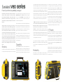
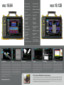
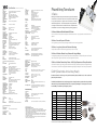
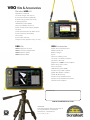
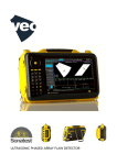
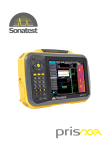
Ultrasonic Phased Array Flaw Detector Series www.sonatestveo.com
Sonatest veo series
Power & performance perfectly packaged.
ing an inspection reference for reporting. All adjustments to focal laws are
be minimized to ensure maximum productivity. Sonatest’s reputa-
instantaneous, with angle resolution to 0.10 and up to 1024 focal laws without
tion for rugged construction and high quality products has been
loss of performance. Multiple scans from different probes may be displayed
earned over 50 years serving the industry. The veo is constructed
and evaluated at the same time. Multiple sectorial scans, true top, side and
to exacting standards using a rigid, shock mounted, internal chassis
end view extractions plus C-Scans are all supported by the veo. TOFD and
surrounded by an impact absorbing enclosure and sealed to IP66.
Help and Wizards guide the user through scan set up whilst
Phased array inspections can be carried out in tandem at full scanning
reinforces Sonatest’s reputation for innovative technician
Optimisation Tips ensure the veo always performs at the highest
speed and with up to 3GB data files large areas can be inspected more
focussed product development. Simple controls, superior
level. The unique 3D ScanPlan view gives immediate visual
efficiently. Full resolution waveform data can be stored directly to a
performance, advanced features and rugged enclosure
confirmation of correct set up and ultrasound coverage, even in
removable USB data key for ease of back up and transfer to PC.
deliver simplicity, capability and reliability to the technician’s
complex multi-probe applications.
The veo range of Phased Array ultrasonic flaw detectors
The veo has two dedicated mono element flaw detection chan-
finger tips.
Fast and efficient wizards for Sound Velocity, Wedge Delay, TCG,
nels for conventional UTand TOFD inspection. Based on Sonatest’s
Ultrasonic Phased Array technology has become the
DAC, Sensitivity and Encoder calibration are all provided as stan-
Masterscan flaw detector the channels have 400 V pulsers, Time
established method for advanced NDT testing applications.
dard. Clear indication of the calibration status is provided on screen
Corrected Gain and low noise amplifiers, for the most demanding
Phased Array techniques allow the user to control parameters
via a simple traffic light system, so that operators can check at a
applications. An impressive hardware specification provides high
such as beam angle and focal distance to create an image
glance that the veo is calibrated for the inspection task.
quality ultrasonic data, via a full 16 bit high speed architecture and 12
of the test part; enhancing defect detection and speed of
testing. In addition, using the latest computer technology,
data can be permanently recorded for processing and report
generation. The veo’s robust design, intuitive user interface
and extensive online help brings the power of Phased Array to
the field-based technician. Typical applications include Weld
Inspection, Corrosion Mapping, Aerospace and Composite
testing.
Simplicity
The intuitive menu system is application and workflow driven, with
set up and operation swiftly becoming second nature. Integrated
Menu navigation uses Sonatest’s second generation scroll wheel
technology for fast parameter selection, with shortcut keys for the
most used functions and alphanumeric entry. The familiar Start,
Stop and Record keys switch quickly between set up, acquisition
and recording modes.
Capability
The powerful veo platform unlocks a new level of performance in a
portable instrument, helping you to maximize your efficiency on-site.
The Inspection Plan shows the operator in 2D and 3D where probes are
positioned on the test part, simplifying the inspection setup and provid-
bit ADC technology. Digital signal processing enables smoothing and
averaging, enhances image interpretation. Measurement and sizing
of indications are quickly achieved using advanced measuring tools
Designed to incorporate many features to make site work easier, the
veo is fitted with standard camera mount fittings underneath and
four attachment points on the back for tripods and other equipment
accessories. Additionally the four corner D-rings allow the veo to be
attached to carry straps or 4 point body harnesses, for easy movement and freeing hands for scanning. The veo has a two battery
design which are “hot swappable”, therefore minimising down time
and heightening the reliability of performance in the field.
UT Studio
UT Studio is a PC based software, which comes as part of the
veo package, for Phased Array configuration development,
data analysis and report generation. Recorded veo data files
such as Hyperbolic Cursors for TOFD.
are easily transferred via a network or USB data key and used to
For any flaw detector the display is a crucial element. The Sonatest
drag and drop interface, the user can create multiple views such
veo range has a colour transflective TFT LCD, providing high visibility in all conditions, with the highest display to size ratio of any field
instrument.
Reliability
Robust design and proven reliability are essential attributes in
demanding NDT environments. Down time is expensive and should
generate new views and projections. Using a familiar windows
as Top, End and B-Scan by simply dragging veo data files onto
templates for display.
Powerful measurement cursors and extractors can added be to
identify indications, size and annotate defects. Reports are easily
generated and can be exported into PDF format for review and
circulation. Free download of UT Studio Viewer is available for
the technician’s client.
veo 16:64
Superior Imaging
Huge File Size (3GB)
Full Data Recording
USB key Data Storage
Fast Encoded Scans
WheelProbe Compatible
Multi Scan
Hot Swap Battery Packs
Simultaneous UT & PA
Merged C-Scan
Instant Focal Law
Calculations
Simultaneous
TOFD & PA
Easy Report
Generation
Ray Tracing
with Reflection
IP66 Enclosure
Interface Triggering
(TCG/DAC)
Calibration Wizards
3D ScanPlan
Probe & Wedge
Databases
TCG and DAC
Unlimited Scan Lengths
3D Scanplan
TOFD
The veo Scanplan supports multiple probes and
scans, enabling the set up of inspection plans from a
number of sources quickly and efficiently. Choose from
a range of weld geometries and visualise the probes
on the part in the locations you choose. Multiple skip
paths are shown on the 3D Scanplan allowing the user
to ensure coverage for weld inspections. Simple reference points are indicated for easy interpretation and
locations of probes on the part can be quickly defined.
Mixtures of probe types are supported in pulse echo
and pitch and catch: phased array; TOFD or conventional UT. The Scanplan is an invaluable reference for
your inspection report, communicating the results of
your inspection more clearly, and saved as part of your
inspection for future use.
The veo has a dedicated analogue architecture for
TOFD inspection, using analogue filters developed
from the Sonatest range of flaw detectors. Coupled
with the lowest noise amplifiers, high speed data
acquisition and a high definition display, superior
quality TOFD scans can be viewed live at the same
time as Phased Array. Phased Array and TOFD
inspections can be evaluated together for added
confidence during weld inspection. Built in evaluation
tools, such as straightening and lateral wave removal,
allow quick and accurate evaluation of the TOFD
inspection, which can be included in a test report.
www.sonatestveo.com
Multi Scans
The veo can be quickly configured to display a large
range of multi scan views. This allows the user to select
the views important for the inspection and to get best
use from the display. Sector scan, top, side and end
views can all be combined with multiple A-Scan views
and TOFD. Cursors and rulers are used to identify
indications in the views, whilst measurement tools give
size and annotation.
veo 16:128
16:128 (addtional features)
Up to 128 probe
elements
High Power -130 volts
Enhanced Multigroup
up to 6 concurrent scans
A-Scan
Stop Mode
C-Scan
The veo supports traditional ultrasonic testing with
mono transducers. The high definition LCD and fast
graphics rendering ensure high levels of accuracy
and a fast interactive waveform display. Thanks to
the high resolution of the LCD display, measurements
are clear and easy to read, and the wide screen format provides a huge viewing area for the scan. The
A-Scan display ensures the peak signal is always
displayed so that you never miss a defect.
In stop mode the veo system is able to display four
screens of information simultaneously. For example
a Configurations Summary, Help Page, Plan view of
Inspection (showing expected probe movement),
3D Scanplan (showing the probes, parts, inspection
beams and planes of focus - as above. Any one of
these can be maximised to a full screen view.
The veo offers full merged C-Scan capabilities
allowing the inspector to see the complete
area of inspection. TOP views (from angled or nor-
mal beam inspections) or C-Scans (from normal beam
inspection) can be producec based on either amplitude
or time of flight data. C-Scans from multiple passes can
be merged together. This is particularly valuable for
corrosion mapping and assessment of large composite
structures.
Veo & Corrosion WheelProbe Scanning Systems
The Corrosion WheelProbe is a tried and tested solution for corrosion mapping and can be combined with the veo and scanning system to provide simple
and effective scanning solutions in this field. The scan width is close to 50mm in one pass and can be used on diameters from 12 -120cm (4 - 48 in).
Importantly the tyre allows excellent coupling to rough surfaces, and the design allows for consistent reliable inspection in both depth and amplitude.
Advantages of this system include the portability, relative simplicity and complete autonomy from the need for additional power sources on the inspection site. Additionally the Veo CWP system gives the flexibility of utilising the CWP on a manual basis for small area scans, e.g. screening of pipe work of
vessels (where LRUT has been used) or scanning along the length (Axial) of the pipe.
veo
Specifications (specifications are subject to change)
PHASED ARRAY
Pulsers
Configuration
16:64 (16 pulsers/receivers; driving up to 64 elements)
Test Mode Pulse-Echo and Transmit/Receive
Transducer SocketI-PEX
Pulse Voltage
-50 V to -100 V (in steps of 10 V)
Pulse Shape
Negative square wave (with ActiveEdge)
Pulse Width
adjustable 25ns to 1000ns (2.5ns resolution)
Edge Time
<10 ns in 50 ohms load @100V
Output Impedance<16 ohms
Trigger
Synchronisation
Encoder or free-running (time based)
Tx/Rx Focus Delay Range
0 to 10 µs (2.5 ns resolution)
Receivers
Gain Range
0-84 dB, in steps of 0.1dB
Input Impedance50 ohms
Bandwidth
200kHz - 27MHz (-3 dB)
Data Acquisition
Architecture
Digitizing Frequency
Digitizer Resolution
Data Processing
Data Recording
Max A-Scan Length
Maximum PRF Focal Law Qty
Focusing Type
Processing Filters
Sub-sampling
Rectifier
Reference Full digital delay and sum architecture
50/100 MHz
12 bits
16 bits/sample
Full raw data recorded
8192 samples
(32 metres in steel LW, 50MHz, 1:128)
20 kHz
Up to 1024
Constant Depth, Constant Sound Path, Constant Offset
Smoothing, Averaging, Keep Max, Software Gain
7 narrow bands and 3 broadbands, automatic
1:1 to 1:128
RF, Full, Positive, Negative.
Initial pulse or gate, IFT supported
Scan & Views
Supported Scans
Real Time Views
Colour Maps
Multi-Group
S-Scan & L-Scan
S, L, B, C-Scan, Top and End view.
10 Standard & User customisable pallete
4 scans and 1 TOFD Scan
Cursors
Types
Measurements
Cartesian, Extraction Box, Angular
Path Length, Depth, Surface Distance, DAC, AWS
CONVENTIONAL UT/TOFD (MONO ELEMENT CHANNELS)
Pulsers
No. of Channels
2 TX/RX (2 multiplexed channels)
2 RX
Test Mode
Pulse-Echo, transmit/receive, TOFD
Transducer Socket
BNC or LEMO 1 (factory option)
Pulse Voltage
-400 V (adjustable from -100 to -400 V in steps of 10 V)
Pulse Shape
Negative Square Pulse (with ActiveEdge)
Pulse Width
Adjustable from 25 ns to 2000 ns, resolution 2.5 ns
Edge Time
<20 ns in 50 ohms load @400V
<10 ns in 50 ohms load @150V
Output Impedance
<10 ohms
Receivers
Gain Range
102 dB (-30 dB to 72 dB)
Input Impedance
400 ohms
Filter Bands
Narrow bands centred at 0.5 MHz, 1 MHz, 2.25 MHz
5 MHz, 7.5 MHz, 10 MHz and 15 MHz
Broadband at 1 MHz to 18 MHz (-6dB)
Data Acquisition
Digitizing Frequency
50/100/200 MHz
Digitizer Resolution
10 bits/sample
Data Processing
16 bits
Data Recording
Full raw data
Max. A-Scan Length
8192 samples
Maximum PRF
12 kHz
Processing
Smoothing, Filter, Keep max
Sub-sampling
1:1 to 1:128
Rectifier
RF, Full, Positive, Negative
Trigger Synchronisation External digital input, encoder or internal
Scans & Views
Supported Scans
A-Scans,
Views
A, B-Scan, TOFD
Cursors
Type
Cartesian, Hyperbolic
Measurements
Path Length, Depth, Surface Distance, DAC, AWS, DGS
CONVENTIONAL AND PHASED ARRAY
DAC
Number of Points 16
DAC Quantity
1 with 3 sub-DAC (per focal law in PA)
Time Corrected Gain (TCG)
Number of Points
16
Gain Range
0 to 60 dB
Max Gain Slope
>50 dB/µs
Gates
A-Scan Gates
4 gates per A-scan (3 extracted A-scans per S/L-scan)
Gate TriggerFlank/Peak
S/L-Scan
2 Extraction Boxes per S/L-scan
Alarm LED
1 (sync on all gates & DACs)
Measurements
Available in A-Scan view
1D Peak (FSH, dB, D, BPL, SD)
1D Flank (FSH, dB, D, BPL, SD)
Echo to Echo
Reporting
PDF file, PNG screen captures, customer logo
PDF Reader
Allows viewing any uploaded PDF document
GENERAL
Data Storage
Internal
6 GB (standard)
External
Hot removable “User” USB8 GB (standard)
Only limited by USB key capacity
Transfer Rate
To User Key - Up to 23 MB/s Write mode
Up to 27 MB/s Read mode
Data File size 3GB (FAT32 file system)
Typical Scanning Speed 10 to 15 cm/s (3.9 to 5.9 in/s)
Typical Scan Length
>10 m (32.8ft)
Phased Array Transducers
X-Series
Building on the Phased Array instrumentation range from Sonatest Ltd,
the X-Series of transducers now offer the operator a broader choice
in range and frequencies; together with the assurance of industry
standard configurations. These X-Series phased array probes have
an integral 2.5 metre cable and an IPEX connector, compatible with
the Sonatest veo and other leading phased array testing equipment.
X1 Series - Miniature & Sub-Miniature PA Probes
The X1 models are small probes for aerospace and limited access work. Key applications include “Scribe line” inspection.
Display
Size
Resolution
Colour
Type
25.9 cm (10.2 in) Wide aspect ratio
1024 x 600 pixels
260k (65535 colours for scan palettes)
TFT LCD
I/O Ports
USB Ports
Ethernet
Video Output
3 x USB certified ports (480 Mbps)
Gbit Ethernet (1000 Mbps)
VGA Analog (1024 x 600)
I/O
Encoder
Power Output
1 or 2 axis quadrature encoder (LEMO connectors)
Single ended and differential input
5 V, 500 mA, current limited
Integrated Help
Language Support
Active parameter description and Optimisation Tips.
Six user selectable languages from: English, German,
French, Spanish, Russian, Chinese.
Batteries & Power Supply
Battery Type
Number of Batteries
Operation
Battery Replacement
Battery Recharge
Battery Life
Intelligent Li-ion batteries
2
1 battery or 2 batteries, DC Power pack
Hot swappable - no tools required
Batteries recharge in unit, operating or not
6+ hours (typical operation).
X5 Series - Medium Phased Array Probes - AWS, High Temperature & Deep Penetration
Enclosure
Size
Weight
H220 mm x W335 mm x D115 mm (8.66 in x 13.19 in x 4.52 in)
5.28 kg(11.6 lb) 1 battery/ 5.75 kg (12.6 lb) 2 batteries
DAAH (Detachable Active Array Head)
Environmental
Temperature
Operating -10 oC to 40 oC (14 oF -104 oF).
Storage -25 oC to 70 oC (-13 oF -158 oF)
Relative Humidity
5 to 95% non-condensing
Environmental
Meets IP66
Warranty
1 year.
Calibration StandardEN12668.
Vibration
EN60068-2-6 Sinusoidal vibration, 50hz to 500Hz, 0.5mm, 18g,
5 sweep cycles
According to MIL-STD-810F, Method 516.5, Procedure IV; 26 Shock (drop) Tested
“1-meter drops” (each face, edge, corner), while operating, to
2 inch plywood over concrete.
Veo 16:128 only
X2 Series - General Purpose PA Probes
This is a general purpose compact probe design suitable for sector scanning applications.
X3 Series - Long Array Probes for Electronic Scanning
These probes are ideal for Linear Scanning applications (L-Scan or E-Scan).
X4 Series - Miniature Phased Array Probes with Integral Wedge
An integral wedge design which are dimensionally and ultrasonically equivalent to standard European mono-element
shear wave probes. A good choice where a compact angle beam is required.
These are low frequency high energy probes intended for fairly deep penetration applications and general testing.
These can also be used with the appropriate SW62XXX range wedges, including the “Snail” and high temperature.
Sonatest manufacture a wide range of Array and Mono-element probes suitable for use on the veo and other
phased array flaw detectors.
The DAAH (Detachable Active Array Head) range provides a unique phased array probe solution using standard
cables and a range of detachable probe heads. This concept brings advantages in cost and gives the end user
more flexibility in the field during the inspection process.
PHASED ARRAY
Pulsers
Configuration
16:128 (16 pulser/receivers; driving up to 128 elements)
Pulse Voltage
-50 V to 130 V (insteps of 10V)
Output Impedance<32 ohms
Data Acquisition
Trigger Synchronisation External digital input, encoder or internal
Frequency
Scan & Views
Multi-Group
Up to 6 scans (6 phased array or 4 phased array with 2UT/TOFD)
Supported Inspection Codes
Other relevant Codes are also met.
• ASME Code Case 2235-9 Use of Ultrasonic Examination in Lieu of Radiography
• ASME Code Case 2541 Use of Manual Phased Array Ultrasonic Examination Section V ASME
• ASTM E2491 Standard Guide for Evaluating Performance Characteristics of Phased-Array
Ultrasonic Examination Instruments and Systems
• ASTM E2700 Standard Practice for Contact Ultrasonic Testing of Welds Using Phased Array
• CEN EN 583-6 - Nondestructive testing - Ultrasonic examination - Part 6 -TOFD as a Method
for Defect Detection and Sizing
• BSI BS7706 - Guide to Calibration and Setting-Up of the Ultrasonic TOFD Technique for the
Detection, Location, and Sizing of Flaws
Model Number
No.of Elements Pitch (mm)
Wedge
2.25
T1-PE-2.25M20E1.2P
20
1.2
External
2.25
T1-PE-2.25M14E1.2P-35W0D
14
1.2
350 Integral
2.25
T1-PE-2.25M18E1.2P-17W0D
18
1.2
170 Integral
5
T1-PE-5.0M32E0.8P
32
0.8
External
5
T1-PE-5.0M22E0.8P-35W0D
22
0.8
350 Integral
5
T1-PE-5.0M26E0.8P-17W0D
26
0.8
170 Integral
7.5
T1-PE-7.5M44E0.6P
44
0.6
External
7.5
T1-PE-7.5M30E0.6P-35W0D
30
0.6
350 Integral
7.5
T1-PE-7.5M40E0.6P-17W0D
40
0.6
170 Integral
5 MHz
CWP-05-64-08-05-veo
64
0.8
WheelProbe
2 MHz
CWP-02-64-08-05-veo
64
0.8
WheelProbe
(MHz)
Further transducer models available. Enquire for full range.
veo Kits & Accessories
Standard veo Kit
Calibration Certificate
UT Studio Single user licence
• Conventional Views (A/B/C/D)
• Phased Array Views (S/L-Scan)
• Viewing Reports
USB Memory Stick (8GB)
Lithium-Ion Battery packs x 2
Power Cord & Power Supply adaptor
Couplant
Quick Start Guide & User Manual CD
Screen Protector (Anti-Glare)
Carry Strap
4-point Neck Harness
Transport Case (Airplane carry on size)
veo Kits
veo Accessories
•veo & Magman Scanner
•veo & Corrosion WheelProbe
•veo & Manual TOFD
•veo & Manual Weld
Splash Proof USB Keyboard
Waterproof Mouse
Battery Charger
Tripod
Lithium-Ion Battery pack
UT Studio - Professional edition
QuickTrace Encoder
Rapidscan to veo Encoder Adapter
DAAH Array probe cable
Screen Protector
USB Memory Stick (8GB)
Phased Array Cable Y-Splitter
Splitter Box (32/32 or 64/64)
TOFD 40 dB Pre-amp
Phased Array Test Block Steel
Phased Array Test Block Aluminium
HD15 Encoder Adapter
Distributed by:
www.sonatestveo.com
SONATEST LTD
Dickens Road, Old Wolverton, Milton Keynes, MK12 5QQ, UK.
Tel: +44 (0)1908 316345 Fax: +44 (0)1908 321323
www.sonatest.com
[email protected]
Part No; 147385_Iss 4_08-12
Cert No: Q5036