1
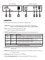
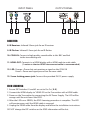
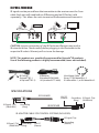
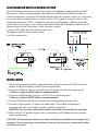
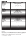
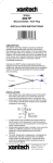
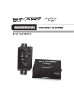
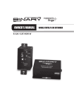
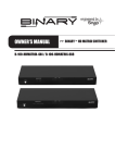
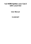
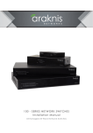
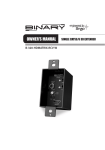
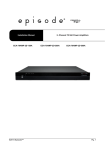
OWNER’S MANUAL Binary™ HDMI over Single Coax >> Extender with IR Pass-Through B-400-1COAX-HDIR WELCOME TO THE BINARY™ BRAND OF PRODUCTS This product is engineered to provide years of exceptional reliability. Binary™ is one of the most highly regarded brands available today. We appreciate your business and we stand committed to providing our customers with the highest degree of quality and service in the industry. IMPORTANT SAFETY INSTRUCTIONS The B-400-1COAX-HDIR HDMI over single coax extender with IR pass-through has been tested for conformity to safety regulations and requirements, and has been certified for international use. However, like all electronic equipment, the B-400-1COAX-HDIR should be used with care. Please read and follow the safety instructions to protect yourself from possible injury and to minimize the risk of damage to the unit. • Follow all instructions and warnings marked on this unit. • Do not attempt to service this unit yourself except where explained in this manual. • Provide proper ventilation and air circulation and do not use near water. • Keep objects that might damage this unit at a safe distance and ensure that the placement of this unit is on a stable surface. • Use only the power adapter, power cords and connection cables designed for this unit. • Do not use liquid or aerosol cleaners to clean this unit. Always unplug the power to the device before cleaning. PACKAGE CONTENTS • (1) B-400-1COAX-HDIR (Transmitter and Receiver) • (4) Mounting Screws • (8) Rubber Feet • (2) 5V Power Supply Units • (1) User manual •(1) IR Adapter Cable INTRODUCTION The B-400-1COAX-HDIR extends HDMI over a single coax allowing video and audio transmission up to 400 ft. In addition, the B-400-1COAX-HDIR is equipped with bi-directional IR pass-through allowing users to send IR control up to a distance of 400ft, making IR control possible without any additional wires. FEATURES • HDMI 1.3a compliant - This unit does NOT support 3D • HDCP compliant • Single RG6 3G Quadshield Solid Copper (75 ohm) coaxial cable extends the transmission range up to 400 ft. from the HDMI source and supports up to 1080p60 with 24-bit color depth • Up to 7.1-channel audio supported including Dolby Digital, DTS, and PCM. This unit does NOT support Dolby True HD, DTS-HD, or LPCM. • Video resolutions supported are 480i, 720p, 1080i, and 1080p. This unit does NOT support 480p. • Bi-directional IR with IR Adapter Cable to connect to control systems • Wall-mountable housing design for easy installation Note: The transmission distance is subject to the quality of installed coax cable, source device, and display. Higher resolutions and longer transmissions require high quality cabling. RG6 3G Solid copper quadshield 75 Ohm cable and 75 ohm BNC connectors are recommended. Any connections along the transmission path will reduce the transmission performance. INPUT PANEL 1 2 OUTPUT PANEL 3 4 5 6 7 TRANSMITTER NOTE: Transmission distance up to 400 feet at 1080p (24-Bit) 1. HDMI-IN: Connects to a HDMI source with a HDMI male-to-male cable. (1 meter or shorter HDMI interconnect cable is recommended) 2. LED: Orange = Power but no HDMI input signal. Green = Power and HDMI signal present. 3. MODE (2-pin DIP Switch): Please see table below for detailed information Pin #1 Pin #2 EDID MODE OFF () OFF ) Up to 1080p/60 with 7.1 Dolby Digital, DTS, PCM audio support Also supports 1080p/30, 1080p/24, 1080i/60, 720p/60, 480i/60 ON () OFF () Up to 720p/60 with Stereo audio support Also supports 1080p/30, 1080p/24, 1080i/60, 480i/60 OFF () ON () Up to 1080p/60 with Stereo audio support Also supports 1080p/30, 1080p/24, 1080i/60, 720p/60, 480i/60 ON () ON () EDID Learning Mode Note: 480p is not supported 4. COAX-OUT : Connect a high-quality coaxial cable to this BNC and link to the receive unit 5. IR Receiver: Infrared 3.5mm jack for an IR receiver or IR adapter cable for connection to a control system 6. IR Flasher: Infrared 3.5mm jack for an IR flasher 7. Screw-locking power jack: Connect the provided 5V DC power supply INPUT PANEL 8 9 10 OUTPUT PANEL 11 12 13 RECEIVER 8. IR Receiver: Infrared 3.5mm jack for an IR receiver 9. IR Flasher: Infrared 3.5mm jack for an IR flasher 10. COAX-IN: Connect a high-quality coaxial cable to this BNC and link to the transmitting unit 11. HDMI-OUT: Connects to a HDMI display with a HDMI male-to-male cable. (1 meter or shorter HDMI interconnect cable is recommended) 12. LED: Orange = Power but not receiving a signal on the COAX-IN Green = Power and signal present on the coax cable 13. Screw-locking power jack: Connect the provided 5V DC power supply EDID LEARNING 1. Ensure DIP Switches #1 and #2 are set to On-On [-]. 2.Connect the HDMI display to “HDMI-IN” on the Transmitter with a HDMI cable. 3.Power on the Transmitter by connecting the 5V Power Supply. The LED will be orange until the unit learns the EDID. 4.After the LED turns GREEN, the EDID Learning procedure is complete. The LED will remain green until the HDMI cable is removed. 5.Unplug the HDMI cable from the display and follow the installation instructions. DO NOT change the DIP switches or the EDID information will be lost. IR PASS-THROUGH IR signals can be passed from the transmitter to the receiver over the Coax cable. Each unit will need both an IR Receiver and an IR Flasher (sold separately). This allows the units to receive IR information and transmit it. CAUTION: Incorrect connection of the IR Flasher and Receiver may result in IR extender failure. Check carefully before plugging in the IR extender to the respective IR sockets. Warranty will not cover the damage. NOTE: This product was specifically engineered for Episode® IR products. Use of the following products is highly recommended (items not included). IR Flasher (Episode® IRF-1 or Episode® IRF-2) IR Receiver (Episode® IR-SM-3660 or Episode® IR-TT-3660) Mini Mono Cable Binary™ B3-MonoMini-.5, B3-MonoMini-1, or B3-MonoMini-2 SPECIFICATIONS IR FLASHER IR Signal (Tip) (20-60 kHz) Grounding (Ring) 12V DC (Sleeve) Grounding IR Signal (Tip) (Ring) (20-60 kHz) IR RECEIVER IR ADAPTER CABLE FOR CONTROL SYSTEMS (INCLUDED) IR Signal (Tip) IR Signal (Tip) (20-60 kHz) Grounding (Ring) 12V DC (Sleeve) Grounding (Sleeve) IR INTEGRATION WITH A CONTROL SYSTEM The IR Receiver connection on the Transmitter is designed to operate with Episode® IR products. When connecting the Transmitter to an IR Remote Control System or Home Automation system to control the display from the control system, it is necessary to convert the connection from a stereo 3.5mm (1/8”) cable to a mono 3.5mm (1/8”) cable and eliminate 12VDC. Included in the box is an IR Adapter Cable to make this connection very simple. First, connect the male end of the IR Adapter Cable to the IR Receiver jack on the Transmitter. Next, connect a mono 3.5mm (1/8”) cable from the female end of the IR Adapter Cable to the control system. Test the connections. INSTALLATION 1. Select the appropriate mode (see transmitter section) or learn the EDID from the display to the transmitter (see EDID learning Section). 2. Connect a HDMI source (such as a Blu-ray Disc player) to the transmitting unit. (1 Meter or shorter HDMI cable is recommended). 3. Connect a HDMI display (such as a LCD TV) to the receiving unit. (1 Meter or shorter HDMI cable is recommended). 4. Connect IR Flashers/Receivers to both transmitting and receiving units. 5. Connect a high-quality 75 ohm coax cable with 75 ohm BNC terminations between the units, ensuring the cable is tightly connected. WARNING: Do not make termination to the coax while connected to the extender 6. Plug in the 5V DC power supply units to the power jack of both the transmitting and receiving units. CAUTION: All terminations to the coax cable should be made before connecting to the extender. Do not make coax terminations if one end of the coax is connected to either end of the extender. SPECIFICATIONS Technical Transmitter Receiver HDMI Compliance HDMI 1.3a (Does not support 3D) HDCP Compliance Yes Video Bandwidth Single-link 225MHz (6.75Gbps) Video Support 480i / 720p / 1080i / 1080p60 (Does NOT support 480p) HDMI over Coax transmission range Full HD [1080p 24-bit color] – 400ft Surround sound (up to 7.1ch) or stereo digital audio (Does NOT support Dolby True HD, DTS-HD or LPCM) Audio Support HDMI equalization Auto Input TMDS Signal 1.2 Volts (peak-to-peak) Input DDC Signal 5 Volts (peak-to-peak, TTL) [1] Human body — ±19kV [air-gap discharge] ESD Protection PCB Stack-Up & ±12kV [contact discharge] [2] Core chipset — ±4kV 6-layer board [impedance control — differential 100Ω; single 50Ω] IR Pass-Through Bi-directional Input 1x HDMI, 1x 3.5mm 1x BNC, 1x 3.5mm IR Output 1x BNC, 1x 3.5mm IR 1x HDMI, 1x 3.5mm IR Remote Control Carrier frequency: 20-60kHz HDMI Connector Type A (19-pin female) BNC connector 75Ω interlocking socket 3.5mm Connector 3.5mm jack for IR flasher and IR receiver Mechanical Housing Dimensions (L x W x H) Weight Power Supply Power Consumption Operation Temperature Storage Temperature Relative Humidity Metal enclosure TX and RX each 3” x 3” x 1.2” TX and RX each 11oz 5VDC 4A Interlocking power supply 6 Watts (max) 32~104°F -4~140°F 20~90% RH (no condensation) *Note: Specifications are subject to change without notice. Dimensions and weight are approximate. WARRANTY 2-Year Limited Warranty This Binary™ Product has a Two-Year Limited Warranty. This warranty includes parts and labor repairs on all components found to be defective in material or workmanship under normal conditions of use. This warranty shall not apply to products which have been abused, modified or disassembled. Products to be repaired under this warranty must be returned to SnapAV or a designated service center with prior notification and an assigned return authorization number (RA). For Technical Support: 1-866-838-5052