1
OWNER’S MANUAL
B-320-1CAT-HDIR-W
SINGLE CAT5E/6 3D EXTENDER
B-320-1CAT-HDIR-W Installation and Users Manual
pg.2
B-320-1CAT-HDIR-W Installation and Users Manual
IMPORTANT SAFETY INSTRUCTIONS
WARNING: To reduce the risk of fire or electric shock, do not expose this apparatus to rain or moisture.
1. Read and follow all instructions and warnings in this manual. Keep for future reference.
2. Do not use this apparatus near water.
3. Clean only with a dry cloth.
4. Do not block any ventilation openings. Install according to manufacturer’s instructions.
5. Do not install near any heat sources such as radiators, heat registers, stoves or other apparatus
(including amplifiers) that produce heat.
6. Do not override the safety purpose of the polarized or grounding-type plug. A polarized plug has
two blades - one wider than the other. A grounding type plug has two blades and a third grounding
prong. The wide blade or the third prong is provided for your safety. If the provided plug does not fit
into your outlet, consult an electrician for replacement of the obsolete outlet.
7. Protect the power cord from being walked on or pinched particularly at plug, convenience
receptacles, and the point where it exits from the apparatus.
8. Only use attachments/accessories specified by the manufacturer.
9. Refer all servicing to qualified service personnel. Servicing is required when the apparatus has
been damaged in any way, such as when the power-supply cord or plug is damaged, liquid has
been spilled or objects have fallen into the apparatus, the apparatus has been exposed to rain or
moisture, does not operate normally, or has been dropped.
10. DO NOT EXPOSE THIS EQUIPMENT TO DRIPPING OR SPLASHING AND ENSURE THAT NO OBJECTS
FILLED WITH LIQUIDS, SUCH AS VASES, ARE PLACED ON THE EQUIPMENT.
11. TO COMPLETELY DISCONNECT THIS EQUIPMENT FROM THE AC MAINS, DISCONNECT THE POWER
SUPPLY CORD PLUG FROM THE AC RECEPTACLE.
12. THE MAINS PLUG OF THE POWER SUPPLY CORD SHALL REMAIN READILY OPERABLE.
CAUTION: TO REDUCE THE RISK OF ELECTRICAL SHOCK, DO NOT REMOVE COVER.
NO USER SERVICEABLE PARTS INSIDE. REFER SERVICING TO QUALIFIED SERVICE
PERSONNEL.
CAUTION
CAUTION: TO REDUCE THE RISK OF
ELECTRICAL SHOCK.
DO NOT REMOVE COVER. NO USER
SERVICEABLE PARTS INSIDE.
REFER SERVICING TO QUALIFIED
SERVICE PERSONNEL.
© 2012 Binary
The lightning flash with arrowhead symbol, within an equilateral triangle,
is intended to alert the user to the presence of un-insulated dangerous
voltage within the product’s enclosure that may be of sufficient magnitude
to constitute a risk of electric shock to persons.
The exclamation point within an equilateral triangle is intended to alert the
user to the presence of important operating and maintenance (servicing)
instructions in the literature accompanying the appliance.
pg.3
B-320-1CAT-HDIR-W Installation and Users Manual
TABLE OF CONTENTS
1. Overview.......................................................................................................................... 5
2. Package Contents........................................................................................................... 5
3. Features........................................................................................................................... 6
4. Connections and Controls.............................................................................................. 7
4.1. Transmitter Connections and Controls..........................................................................................7
4.2. Receiver Connections and Controls................................................................................................8
5. Basic Connections........................................................................................................... 9
5.1. HD Link(RJ45) Connections................................................................................................................9
5.2. IR Control Connections.......................................................................................................................10
5.2.1. IR Receiver In (3.5mm {1/8”} Stereo) Connections.............................................................11
5.2.2. IR Control In and IR Flasher Out (3.5mm {1/8”} Mono) Connections�������������������������11
5.3. HDMI Out to Display (HDMI).............................................................................................................11
5.4. Optional Remote Power (2 Conductor) Connections..............................................................12
6. Installation..................................................................................................................... 13
6.1. B-320-1CAT-HDIR-W Transmitter Installation..............................................................................13
6.2. B-320-1CAT-HDIR-W Receiver Installation...................................................................................13
6.3. EDID Configuration..............................................................................................................................14
6.3.1. EDID Mode Settings......................................................................................................................14
6.3.2. Learning EDIDs...............................................................................................................................14
6.4. Distance Calibration.............................................................................................................................14
7. Specifications................................................................................................................. 15
8. WARRANTY..................................................................................................................... 16
9. Contacting Technical Support....................................................................................... 16
pg.4
B-320-1CAT-HDIR-W Installation and Users Manual
1. OVERVIEW
The B-320-1CAT-HDIR-W extends HDMI over single Cat5e/6 providing video and audio transmission
to remote displays. In addition, the B-320-1CAT-HDIR-W is equipped with bi-directional IR passthrough allowing users to have bi-directional IR control with no additional wires.
Since many installations are behind flat screen TVs, the B-320-1CAT-HDIR-W Receiver is made
to mount in a single gang box and can be optionally powered from the rack to a rear power
connection.
The B-320-1CAT-HDIR-W also supports the most advanced 3D video format, which is compliant with
HDMI 3D specifications, and guarantees the highest 3D video compatibility on the market.
2. PACKAGE CONTENTS
(1) B-320-1CAT-HDIR-W (Transmitter)
(1) B-320-1CAT-HDIR-W (Receiver)
(4) Mounting Screws
(4) Rubber Feet
(2) 5V DC 2A Power Supply
(1) IR Adapter Cable
(1) WPS-ACC-PWR DC Power Plug (Female)
(1) Decora Wall Plate
(1) User Manual
© 2012 Binary
pg.5
B-320-1CAT-HDIR-W Installation and Users Manual
3. FEATURES
Form and Function
• In Wall Receiver (single gang box) Design for Easy Installation
• Extends HDMI Signals via a Single Cat5e/Cat6
Resolution
Cat5e
Cat6e
1080i / 720p 24-bit color
200ft
200ft
Full HD 1080P 24-bit color
130ft
165ft
Full HD 1080P 36-bit deep color
65ft
65ft
• Support for HDMI 3D
• HDCP 2.0 Compliant
• Adjustable 8-Level Distance Equalization Control
• Rear power Connection enables remote powering
Audio
• All HDMI Supported Formats including DTS-HD Master and Dolby TrueHD
IR Functionality
• Supports IR Signal from 20khz To 60khz
• Bi-Directional IR Pass-Through
• Adaptive IR Input supports IR signals from 3.5V To 12V
*Note: The transmission distance is subject to the quality of installed cable(s), source device,
and display. Only point to point cable connections are supported. Keystone or other connecting
devices should not be used. To minimize the chance of EMI interference, STP (Shielded Twisted
Pair) cable is recommended.
pg.6
B-320-1CAT-HDIR-W Installation and Users Manual
4. CONNECTIONS AND CONTROLS
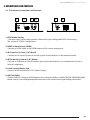
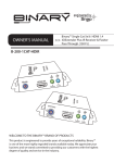
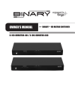
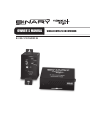
4.1. Transmitter Connections and Controls
1
2
3
4
5
6
1. EDID Mode Setting
7 position rotary switch that provides selection of 6 pre-configured EDIDs and learning.
See section: 6.3 EDID Configuration.
2. HDMI In from Source (HDMI)
Connect an HDMI cable to the HDMI output of the source component.
3. IR Control In (3.5mm {1/8”} Mono)
Connect an IR Control System to send IR signals to the Receiver in the remote location.
4. IR Flasher Out (3.5mm {1/8”} Mono)
Connect an IR flasher to send IR control signals from the Receiver to an Automation System or
Source Component.
5. Latch-Locking Power Jack
Connect to the included 5V DC 2A Power Supply.
6. HD Link (RJ45)
Connect to RJ45 1Cat input of the Receiver; this connection follows standard TIA/EIA-568B. While 568A
can be used, its use will degrade performance due to the nature of the signals being transmitted.
© 2012 Binary
pg.7
B-320-1CAT-HDIR-W Installation and Users Manual
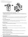
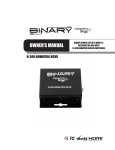
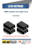
4.2. Receiver Connections and Controls
1
2
7
3
1
4
2
8
3
4
0
5
6
7
9
5
6
1. Optional Remote Power (2 Conductor removable)
Optional connection for power from a remote power source; this connection requires a wire
run within the wall. Use only when the Latch-Locking Power Jack (3) is not being used. Do not
connect both power sources.
2. HD Link (RJ45)
Connect to RJ45 output of the Transmitter; this connection follows standard TIA/EIA-568B. While
568A can be used, its use will degrade performance due to the nature of the signals being
transmitted.
3. Latch-Locking Power Jack
Connect to the included 5V DC 2A Power Supply. Use only when the Optional Remote Power
connector (1) is not being used. Do not connect both power sources.
4. Distance Control
8 position rotary switch that provides equalization control to prevent over or under loading the
HD signal. See Distance Calibration for more details.
5. Power LED
Indicates current state of Power, illuminates GREEN when power is applied.
6. Signal Link LED
Indicates linking status with the Transmitter, illuminates YELLOW when active CAT5E/6
cable is attached.
7. IR Flasher Out (3.5mm {1/8”} Mono)
Connect an IR flasher to send IR control signals from Automation System connected to the
Transmitter to a TV or other device.
8. IR Receiver In (3.5mm {1/8”} Stereo)
Connect an IR Receiver to send IR signals to the Transmitter from the remote location.
9. HDMI Out to Display (HDMI)
Connect an HDMI cable to the display at the remote location.
pg.8
B-320-1CAT-HDIR-W Installation and Users Manual
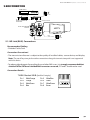
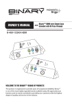
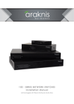
5. BASIC CONNECTIONS
HDMI Source
PLAY
AC Power
B-320-1CAT-HDIR-W
Transmitter
Shielded Cat5e/Cat6
B-320-1CAT-HDIR-W
Receiver
HDTV
2
1
3
4
0
7
5
6
HDMI
(1meter or less)
AC Power
5.1. HD Link (RJ45) Connections
Recommended Cabling
• Shielded Cat5e/Cat6
Connection Precautions!
• The transmission distance is subject to the quality of installed cables, source device, and display.
Note: The use of keystone jack or other connections along the transmission path is not supported
with this device.
• To reduce video dropouts from ceiling fans and other EMI issues, it is strongly recommended that
shielded CAT5e/CAT6 and shielded RJ45 connectors are used; “EZ-ends” should not be used.
Connection Details:
TIA/EIA Standard 568-B (Gold Pins Facing Up)
Pin 1
Pin 2
Pin 3
Pin 4
© 2012 Binary
White/Orange
Orange
White/Green
Blue
Pin 5
Pin 6
Pin 7
Pin 8
White/Blue
Green
White/Brown
Brown
pg.9
B-320-1CAT-HDIR-W Installation and Users Manual
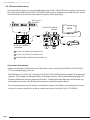
5.2. IR Control Connections
Bi-directional IR signals are transmitted between the B-320-1CAT-HDIR-W transmitter and receiver
over the Cat5e/6 cable. Each B-320-1CAT-HDIR-W will need an IR Receiver to send IR to the source,
and an IR flasher to use IR sent from the IR Controller (sold separately).
A
A
IR Outputs
IR Processor /
Controller
IR Inputs
B-320-1CAT-HDIR-W
Receiver
HDTV
C
A
22
11
33
44
00
B
77
55
66
C
B-320-1CAT-HDIR-W
Transmitter
A 3.5mm {1/8”} Mono-See Section 5.2.2
B 3.5mm {1/8”} Stereo-See Section 5.2.1
C Shielded Cat5e/Cat6 (RJ45)-See Section 5.1
Connection Precautions!
• Before connecting an IR Receiver or an IR control system, verify that the B-320-1CAT-HDIR-W is
OFF to avoid damaging the unit.
• The IR Receiver In (3.5mm {1/8”} Stereo) on the B-320-1CAT-HDIR-W Receiver provides 9V to power IR
receivers. This voltage can damage flashers and control systems. Take caution before plugging an IR
Flasher or IR Receiver into the respective IR sockets. The Manufacturer’s Warranty will not cover any
damage that may occur. See IR Control Connections section for proper cabling.
• Pin out configurations for IR receivers and control systems vary. Before connecting to this input,
review this section carefully in order to match the pin outs for the B-320-1CAT-HDIR-W.
pg.10
B-320-1CAT-HDIR-W Installation and Users Manual
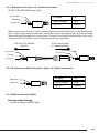
5.2.1. IR Receiver In (3.5mm {1/8”} Stereo) Connections
(B-320-1CAT-HDIR-W Receiver Only)
9V DC (Sleeve)
GND (Ring)
IR Signal (Tip)
IR Signal
Tip
GND (Ground)
Ring
+9V DC
Sleeve
When connecting a control system or connecting block to the IR Receiver In on the Receiver, the
9V DC (Sleeve) must not be connected. Connections of this type require the use of the included
Stereo to Mono IR Adaptor or a custom cable. A mono 3.5mm cable should not be used as it will
short out the 9 VDC to GND and will make the connection inoperable.
To B-320-1CAT-HDIR-W
Receiver
To IR Control System
or Connecting Block
GND (Sleeve)
9V DC (Sleeve)
IR Signal (Tip)
GND (Ring)
IR Signal (Tip)
5.2.2. IR Control In and IR Flasher Out (3.5mm {1/8”} Mono) Connections
GND (Sleeve)
IR Signal (Tip)
IR Signal
Tip
GND (Ground)
Ring
+9V DC
Sleeve
5.3. HDMI Out to Display (HDMI)
Recommended Cabling
• 1 meter or shorter HDMI Cable
© 2012 Binary
pg.11
B-320-1CAT-HDIR-W Installation and Users Manual
5.4. Optional Remote Power (2 Conductor) Connections
(B-320-1CAT-HDIR-W Receiver Only)
Power for the B-320-1CAT-HDIR-W receiver can be supplied via a remote power source when use
of the Latch-Locking Power Jack is not desired. The connection is a 2 conductor removable plug
located on the rear of the B-320-1CAT-HDIR-W receiver.
Recommended Cabling
• One 18 gauge per leg or Two 22/ 24 gauge per leg
Connection Precautions!
• Observe the connections polarity markings. Reversing the polarity may cause damage to the product.
• DO NOT use this connection and the Latch-Locking Power Jack Connection simultaneously. Doing so
may cause damage to the product.
Connection Details:
+5V DC 2A
- (GND)
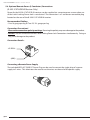
Connecting a Remote Power Supply
The included WPS-ACC-PWR DC Power Plug can be used to convert the single plug of a power
supply to 2 wires. This eliminates the need to cut the wires on the end of the power supply.
pg.12
B-320-1CAT-HDIR-W Installation and Users Manual
6. INSTALLATION
Note: Do Not connect power to the B-320-1CAT-HDIR-W until all other connections are made and
the unit is installed.
6.1. B-320-1CAT-HDIR-W Transmitter Installation
1. Run the cabling in the wall to the location for the B-320-1CAT-HDIR-W:
HD Link Cable:
ShieldedCat5e/Cat6
Remote Power (Optional):
(See above)
2. Mount the B-320-1CAT-HDIR-W Transmitter in the desired location.
3. Install the Remote Power supply (Optional). See 5.4 Optional Remote Power (2 Conductor).
4. Connect the HDMI out of a source component using an HDMI cable.
5. Connect the cables from the wall to the B-320-1CAT-HDIR-W transmitter.
6. Connect the 5V DC 2A Power Supply to the Latch-Locking Power Jack
7. Select the desired EDID setting using the EDID Mode Selector dial. See 6.3 EDID Configuration.
Note: If an EDID was learned into the transmitter, DO NOT move the dial away from 7 as the
EDID will be lost.
8. Install the B-320-1CAT-HDIR-W receiver following the steps outlined below.
6.2. B-320-1CAT-HDIR-W Receiver Installation
1. Run the cabling in the wall from the head end:
HD Link Cable:
Shielded Cat5e/Cat6
Remote Power (Optional):
(See above)
2. Install the B-320-1CAT-HDIR-W transmitter following the steps outlined in section 6.1.
B-320-1CAT-HDIR-W Transmitter Installation.
3. Connect the cables from the wall to the B-320-1CAT-HDIR-W receiver.
4. Install the B-320-1CAT-HDIR-W into the junction box mounted in the wall.
5. Connect an IR Flasher and/or IR receiver being used.
6. Connect an HDMI cable from the B-320-1CAT-HDIR-W to the display.
7. Connect the 5V DC 2A Power Supply to the Latch-Locking Power Jack if remote power is
not being used.
8. Set the Distance Control rotary switch to 7 (Weakest).
9. Plug the local or remote power supply into an AC outlet.
10. Calibrate for distance. See 6.4 Distance Calibration for details.
© 2012 Binary
pg.13
B-320-1CAT-HDIR-W Installation and Users Manual
6.3. EDID Configuration
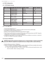
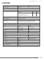
6.3.1. EDID Mode Settings
EDID Setting Supported Resolutions Color Depth
Audio Channels
0
1080p @60Hz
24-Bit
7.1 ch
1
1080p @60Hz
24-Bit
2 ch
2
1080p @60Hz
36-Bit
7.1 ch
3
1080p @60Hz
1080p @30Hz
24-Bit 3D
7.1 ch
4
1080i @60Hz,
720p @60Hz
24-Bit
7.1 ch
5
1080p @30Hz
1080i @60Hz
720p @60Hz
24-Bit
2 ch
6
1080p @60Hz
24-Bit 3D
2 ch
7
Learning Mode
—
—
6.3.2. Learning EDIDs
1. Set the EDID Mode dial to “7”.
2. Connect the HDMI display to “HDMI IN” on the Transmitter with a HDMI cable.
3. Set “MODE” on the transmitting unit to “7”.
4. Power on the Transmitter by connecting the 5V Power Supply.
5. The LED on the RJ45 of the transmitter will flash On and Off once to learn the EDID. Keep the
mode dial on “7” at all times to use the learned EDID.
6. Unplug the HDMI cable from the display and follow the installation instructions in section 6.1
B-320-1CAT-HDIR-W Transmitter Installation.
6.4. Distance Calibration
F
CAUTION: Inappropriate signal level setting may cause an overpowering issue that may shorten the
product life. Follow the steps below to adjust the distance setting in order to avoid overdriving.
1. Set the distance control to 7 (Weakest).
2. Select a source that is outputting the highest-quality video that will be transmitted to the receiver.
A. If you see flickering or blinking images on the display:
A.1 - Adjust the signal level from 7 to 0 one step at a time, and stop turning the rotary switch
when the audio/ video is playing normally.
pg.14
B-320-1CAT-HDIR-W Installation and Users Manual
7. SPECIFICATIONS
Technical
Transmitter
Receiver
HDMI Compliance
HDMI 3D
HDCP Compliance
Yes
Video Bandwidth
6.75Gbps
Video Support
480i / 480p / 720p / 1080i / 1080p60
HDMI over UTP Transmission
Resolution
Cat5e
Cat6
1080i / 720p 24-bit color
200ft
200ft
Full HD 1080P 24-bit color
130ft
165ft
Full HD 1080P 36-bit deep color
65ft
65ft
Signal Equalization
8-level digital control at RX
Input TMDS Signal
1.2 Volts (peak-to-peak)
Input DDC Signal
5 Volts (peak-to-peak, TTL)
ESD Protection
(1) Human body model — ±15kV (air-gap discharge)
& ±8kV (contact discharge) (2) Core chipset — ±8kV
IR Signal (Bi-directional)
Carrier frequency: 20-60kHz
Connections
HD Link
1x RJ45
1x RJ45
HDMI
1x HDMI Type A
(19-pin female)
1x HDMI Type A
(19-pin female)
IR Receiver (In)
---
1x 3.5mm Stereo
IR Control In
1x 3.5mmMono
---
IR Flasher (Out)
1x 3.5mmMono
1x 3.5mmMono
Power
Latch-Locking
Latch-Locking + 2 Conductor
EDID Mode
Distance Signal level
Controls
Rotary Control Switch
Mechanical
Housing
Metal enclosure
Dimensions
2.9” x 3.5” x 1”
Weight
1.1 lbs
Power Supply
5V DC 2A
Power Consumption
3 Watt (max)
Operation Temperature
32~104°F
Storage Temperature
-4~140°F
Relative Humidity
20~90% RH (no condensation)
© 2012 Binary
4.14“x 1.75” x 2.36”
pg.15
8. WARRANTY
2-Year Limited Warranty
This Binary™ Product has a Two-Year Limited Warranty. This warranty includes parts and labor repairs on
all components found to be defective in material or workmanship under normal conditions of use. This
warranty shall not apply to products which have been abused, modified or disassembled. Products to
be repaired under this warranty must be returned to SnapAV or a designated service center with prior
notification and an assigned return authorization number (RA).
9. CONTACTING TECHNICAL SUPPORT
Phone: (866) 838-5052
Email:[email protected]
© 2012 Binary™
121018-0930