1
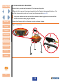
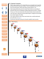
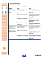
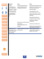
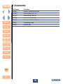
H2S CO CH4 Detective Net User & Operator Manual Click here for navigation instructions Detective Net M070019/ENG Issue 3 Aug 2015 Click here fo contents list Contents NAVIGATION INSTRUCTIONS The symbols in the left-hand margin of each page of the manual will enable you to carry out the following functions: Contents Click on this button to display the Contents page. Click on this button to display the previous page. Click on this button to display the next page. Click on this button to display the previous view (use it to return from a reference jump). Click on this button to display next view (use it to return to a reference jump). Click this button to print some or all of the document (specific pages can be chosen). Exit !! Click this button to exit the user guide. Press the Esc key to display normal Acrobat© Controls. CONTENTS Functional Overview. . . . . . . . . . . . . . . . . . . . . . . . . . . . . . . . . . . . 5 Safety Information. . . . . . . . . . . . . . . . . . . . . . . . . . . . . . . . . . . . . . 6 Glossary. . . . . . . . . . . . . . . . . . . . . . . . . . . . . . . . . . . . . . . . . . . . . 10 1.Operation . . . . . . . . . . . . . . . . . . . . . . . . . . . . . . . . . . . . . . . . . 12 Exit 1.1 In the box. . . . . . . . . . . . . . . . . . . . . . . . . . . . . . . . . . . . . . . . . . . . . . . 12 1.1.1 Box contents. . . . . . . . . . . . . . . . . . . . . . . . . . . . . . . . . . . . . . . . 12 1.2 Device details. . . . . . . . . . . . . . . . . . . . . . . . . . . . . . . . . . . . . . . . . . . . 12 1.3 Connection to Detective. . . . . . . . . . . . . . . . . . . . . . . . . . . . . . . . . . . 13 1.4 LED indications. . . . . . . . . . . . . . . . . . . . . . . . . . . . . . . . . . . . . . . . . . 14 1.4.1 LED1 - Power/Learn Mode (Red LED). . . . . . . . . . . . . . . . . . . . 14 1.4.2 LED2 – Network Status (Red/Amber/Green LED). . . . . . . . . . . 14 1.4.3 LED3 - Alarms (Red LED). . . . . . . . . . . . . . . . . . . . . . . . . . . . . . 15 1.4.4 LED4 – Master/Slave (Green LED). . . . . . . . . . . . . . . . . . . . . . . 15 1.4.5 Battery Indication LED (Red LED). . . . . . . . . . . . . . . . . . . . . . . 15 1.4.6 LED repetition rates . . . . . . . . . . . . . . . . . . . . . . . . . . . . . . . . . . 15 1.5 Function buttons. . . . . . . . . . . . . . . . . . . . . . . . . . . . . . . . . . . . . . . . . 16 1.5.1 Function Button 1 (FB1). . . . . . . . . . . . . . . . . . . . . . . . . . . . . . . 16 1.5.2 Function Button 2 (FB2). . . . . . . . . . . . . . . . . . . . . . . . . . . . . . . 16 1.5.3 Function Button 1 (FB1) & Function Button 2 (FB2) . . . . . . . . 16 1.6 System Configuration. . . . . . . . . . . . . . . . . . . . . . . . . . . . . . . . . . . . . 17 1.6.1 Switching on a device . . . . . . . . . . . . . . . . . . . . . . . . . . . . . . . . 17 1.6.2 Resetting a device. . . . . . . . . . . . . . . . . . . . . . . . . . . . . . . . . . . . 17 1.6.3 Toggle Devices between Master & Slave Functionality. . . . . . 18 1.6.4 Setting Up a Simple Wireless Network. . . . . . . . . . . . . . . . . . . 18 1.6.5 Network connection test. . . . . . . . . . . . . . . . . . . . . . . . . . . . . . . 19 1.6.6 Adding additional slave devices to the network . . . . . . . . . . . 20 1.6.7 Removing Slave Devices from the Network. . . . . . . . . . . . . . . 20 1.6.8 Power Down master or slave device. . . . . . . . . . . . . . . . . . . . . 21 1.6.9 Powering Up a Previously configured network. . . . . . . . . . . . 21 3 1.7 Network Deployment. . . . . . . . . . . . . . . . . . . . . . . . . . . . . . . . . . . . . . 22 1.7.1 Deployment Process. . . . . . . . . . . . . . . . . . . . . . . . . . . . . . . . . . 22 1.7.2 Force Communication . . . . . . . . . . . . . . . . . . . . . . . . . . . . . . . . 23 1.7.3 Network Topology. . . . . . . . . . . . . . . . . . . . . . . . . . . . . . . . . . . . 24 1.8 Alarms and Alerts . . . . . . . . . . . . . . . . . . . . . . . . . . . . . . . . . . . . . . . . 27 1.8.1 Gas alarm. . . . . . . . . . . . . . . . . . . . . . . . . . . . . . . . . . . . . . . . . . . 27 1.8.2 Network Alert. . . . . . . . . . . . . . . . . . . . . . . . . . . . . . . . . . . . . . . . 27 1.8.3 Modulated Alert. . . . . . . . . . . . . . . . . . . . . . . . . . . . . . . . . . . . . . 28 1.9 Network Operation . . . . . . . . . . . . . . . . . . . . . . . . . . . . . . . . . . . . . . . 29 1.9.1 Normal Operation . . . . . . . . . . . . . . . . . . . . . . . . . . . . . . . . . . . . 29 1.9.2 Loss of Connection to Wireless Network . . . . . . . . . . . . . . . . .29 1.9.3 Re-establishing Network Connection. . . . . . . . . . . . . . . . . . . . 30 1.9.4 Detective Net Device - Low Battery Alert . . . . . . . . . . . . . . . . . 31 1.9.5 Detective+ - Power Down or Inadvertent Switch Off. . . . . . . . 31 1.9.6 Internal Fault . . . . . . . . . . . . . . . . . . . . . . . . . . . . . . . . . . . . . . . . 31 2. Detective Net specification. . . . . . . . . . . . . . . . . . . . . . . . . . . 32 3. Service and maintenance . . . . . . . . . . . . . . . . . . . . . . . . . . . . 33 4. Troubleshooting. . . . . . . . . . . . . . . . . . . . . . . . . . . . . . . . . . . . 34 5.Accessories . . . . . . . . . . . . . . . . . . . . . . . . . . . . . . . . . . . . . . . 36 6. RICOCHET™ Mesh Technology . . . . . . . . . . . . . . . . . . . . . . . 37 Warranty. . . . . . . . . . . . . . . . . . . . . . . . . . . . . . . . . . . . . . . . . . . . . 38 Crowcon contacts. . . . . . . . . . . . . . . . . . . . . . . . . . . . . . . . . . . . . 40 Exit 4 Contents Functional Overview ii This manual should be read in conjunction with the Detective+ user manual. Detective Net is a cable replacement wireless solution for Detective or Detective+ allowing wireless transmission of gas alarm events between devices. Overview Glossary Operation Specification Service and maintenance A gas alarm event on a Detective+ shall cause an alert to be transmitted to all other Detective Net devices on the network which in turn will cause all Detective+ units in the network to go into alert. This will ensure that all personnel being protected by the network are alerted to a gas event that may be remote from their current location. Detective Net is simply connected to the existing ‘interconnecting cable connector’ and is supplied with a clip for mounting. A Detective Net device can be configured as either a master or a slave device and a full wireless network can consist of one master device master and up to 25 slave devices. The wireless network can be either configured prior to deployment or once the devices are deployed. It is also possible to add or remove further slave devices once a network is configured and operational. Troubleshooting Accessories Warranty Contacts Exit 5 Contents Safety Information • Detective Net is a hazardous area certified product and as such must be operated and maintained in strict accordance with the instructions, warnings and label information included in this manual. Detective Net must be operated within the limitations stated. • This document is applicable to Detective Net 433 and Detective Net 868. • Read and understand all instructions in this manual prior to use. Overview Glossary Operation Specification Service and maintenance Troubleshooting Accessories Warranty Contacts • Before use ensure that the equipment is in good condition and that the enclosure is intact has not been damaged in any way. • If there is any damage to the equipment do not use, contact your local Crowcon office or agent for repair/replacement • There are no user replaceable internal parts and only Crowcon or Crowcon agent service personnel can service this product. • Only genuine Crowcon replacement parts must be used; substitute components may impair intrinsic safety and invalidate safety certification and warranty of Detective Net. • Detective Net has a non-rechargeable battery that must only be changed in non-hazardous (safe) areas by Crowcon or Crowcon agent service personnel • No live maintenance is permissible • Observe all warnings and instructions marked on the unit and within this manual. • If this product is not working properly, read the troubleshooting guide and/or contact your local Crowcon office or agent, for details reference the ‘Crowcon Contacts’ section of the manual • Risk of static discharge. During installation in a fixed location take care to avoid static generating mechanism. Once installed do not touch certification label on rear of device if a flammable hazard is present. • The metal connector shell has a capacitance of 7 pF when measured in accordance with IEC/ EN60079-0. Installations where the resistance to earth of this exposed metal surface is greater than 1G Ω must consider the potential electro-static charge risk (e.g. in accordance with CLC/ TR 50404 or other relevant publications). • Detective Net should be used with one of the following interconnection cables, Crowcon part number E070010, E070012 & E070028, having the following parameters: Cmax = 15 nF/m; Lmax = 75 uH/m, Rmin = 30 mΩ/m. Exit 6 Contents Overview Glossary Operation Specification Service and maintenance Troubleshooting Accessories • The entity parameters of Detective Net are: Uo = 3.7 V Ui = 10 V Io = 14.3 mA Ii = 25 mA Po = 8.7 mW Pi = 62.5 mW Co = 999 uF Ci = 240 nF Lo = 173 mH Li = 0 Lo/Ro = 2.68 mH/Ω • When used and installed in accordance with IEC/EN60079-25 and IEC/EN60079-14, Detective NET is suitable for use in Zones 0, 1, 2 for Groups IIA, IIB or IIC and Temperature Classes T1 – T4 provided any device(s) Detective NET is connected to also provides an appropriate Level of Protection, Group Classification and Temperature Classification. • The following conditions must also be met: Other Device(s) Other Device(s) Ui> 3.7 V Uo< 10 V Ii > 14.3 mA Io < 25 mA Pi > 8.7 mW Po < 62.5 mW Ci + Ccable< 999 uF Co >Ccable + 240 nF Li + Lcable< 173 mH Lo >Lcable • When Detective NET is connected to multiple other devices the system must be considered per IEC/EN60079-25. • Detective Net meets the dielectric strength requirement of clause 6.3.13 in IEC/EN60079-11. Warranty Contacts Exit 7 Contents Certification label The certification marking is as follows: Figure 1: Certification label IIII 11 GG Overview 1180 1180 Ex ia ia IIC IIC T4 T4 Ga Ga Tamb: Tamb: -20°C -20°C to to +55°C +55°C Ex IECExULD ULD13.0004X 13.0004X IECEx DEMKO13 13ATEX ATEX1255796X 1255796X DEMKO WARNING--ELECTRO ELECTROSTATIC STATICHAZARD. HAZARD. WARNING REFERTO TOMANUAL MANUALM07006 M07006BEFORE BEFOREUSE. USE. REFER Glossary 2172 BLACKLANDS WAY BROOK DRIVE ABINGDON BUSINESS MILTON PARK PARK OX144SD 1DY OX14 UNITEDKINGDOM KINGDOM UNITED Operation Specification Service and maintenance Troubleshooting Accessories Warranty Contacts • Detective Net is certified for use in ambient temperatures in the range -20°C to +55°C (-4 to 131°F). Applicable Standards Refer to equipment marking for confirmation of applicable certification before use. IECEx IEC 60079-0 6th Edition (2011) Electrical apparatus for explosive gas atmospheres Part 0: General requirements IEC 60079-11 6th Edition (2012) Explosive atmospheres - Part 11: Equipment protection by intrinsic safety “i” IEC 60079-26 2nd Edition (2009) Explosive atmospheres - Part 26: Equipment with protection level (EPL) Ga Ex ia IIC T4 Ga Tamb -20°C to +55°C IECEx ULD 13.0004X Exit 8 Contents ATEX EN 60079-0:2012 Electrical apparatus for explosive gas atmospheres Part 0: General requirements EN 60079-11: 2012 Explosive atmospheres - Part 11: Equipment protection by intrinsic safety “i” Overview Glossary IEC 60079-26:2007 Explosive atmospheres - Part 26: Equipment with protection level (EPL) Ga Operation Specification Service and maintenance II 1 G Ex ia IIC T4 Ga Tamb -20°C to +55°C DEMKO 13 ATEX 1255796X Troubleshooting Accessories Warranty Contacts Exit 9 Contents Glossary This section details the terms used within this manual. Detective Net Master Device One device in each network must be configured to be a master device that will control the network and all slave devices. Overview Glossary Operation Specification Service and maintenance Troubleshooting Accessories Warranty Contacts Detective Net Slave Device A network will consist of one master device that controls the network; all other devices will be slave devices. Network Hopping Network hopping describes the process of the master Detective Net device communicating not directly with a slave device but by passing the message through another slave device, or ‘hopping’. Learn Mode All slave devices must be configured to operate with the master device in the wireless network. Learn Mode describes the process of learning a slave device to the master device. Slave devices must be learned to the network prior to deployment. Gas alarm A gas alarm is initiated when a Detective+ unit detects gas and goes into alarm with the beacon and lights in operation. Network Alert A network alert is the response of the network to a gas alarm event on a Detective+ unit within the network. A network alert will cause all other Detective+ units within the network to go into network alert mode, beacon and lights will flash at a slower rate than a gas alarm to differentiate it. Force Communication If no wireless connection exists between devices, the force communication feature can be utilized to re-establish communications by pressing any button on a slave device. Exit 10 Contents Modulated Alert A Modulated Alert is a response of Detective Net to a problem with the Detective Net device, for example if a slave Detective Net device has lost connection to the network a modulated alert will be sent to the locally-attached Detective+. The will cause Detective+ to go into Modulated Alert, the beacon and lights will flash for 3 seconds followed by a 5 second pause; this pattern will then be repeated. Network Connection Test Overview Glossary Operation Specification Service and maintenance Once a network has been configured, deployed and connected to Detective+ units it is possible to undertake a network connection test to ensure all Detective Net units are configured correctly and are within range on the network. A Network Connection Test will cause all devices configured within the network to be placed in Network Alert for 10 seconds. RICOCHET™ Mesh Network Each Detective Net device can provide alternative wireless transmission routes. Should a wireless connection between two Detective Net devices weaken, the network automatically re-routes communication via alternative Detective Net device. This creates a mesh type network allowing a more robust and efficient wireless network. Troubleshooting Accessories Warranty Contacts Exit 11 Contents 1.Operation 1.1 In the box Remove the Detective Net from the packaging and check for any visible damage. The following items will be included as standard: 1.1.1 Box contents • Detective Net Overview • Connection cable • Mounting adapter Glossary Operation • Quick start guide • CD Manual The box label details the contents. Specification 1.2 Device details Service and maintenance The main components of the Detective Net are shown in Figure 2 below: Troubleshooting Accessories Warranty Contacts Figure 2: Device details  ŠÀ Function Button 1 (FB1) Á Function Button 2 (FB2)  Indicator LEDs à Low battery indicator Ä Cable connector Å Detective+ Fixed Æ Á Mount Bracket Æ Bracket securing screws À Ä Ã Exit 12 Contents 1.3 Connection to Detective Detective Net is provided with a standard 0.7m interconnecting cable. If Detective Net is required to be placed remotely from the Detective the standard Detective+ 10m and 20m interconnecting cable can be used (see Accessories table page 36). ii Only these cables must be used and the maximum cable length must not exceed 20m otherwise intrinsic safety may be impaired. Overview Glossary Connect the Detective Net to a Detective+ module as shown in below: Figure 3: Connection Operation Specification Service and maintenance Troubleshooting Accessories Warranty Contacts Exit 13 Contents 1.4 LED indications Detective Net provides four LED indications (numbered 1 to 4) À to provide information as to the status of the wireless device, network, alarm or alert. There is also a battery status LED Á. Figure 4: LEDs À Overview Glossary Operation Specification Á Service and maintenance Troubleshooting Accessories 1.4.1 LED1 - Power/Learn Mode (Red LED) Indicates that the device is either powered up and/or in network learn mode. Warranty Single flash Continuous flash Contacts 1.4.2 LED2 – Network Status (Red/Amber/Green LED) Powered up in normal operation Device in Learn Mode Indicates the current status of the network connection or the status result of Learn Mode. LED2 - Single Flash green Master Device Slave Device Network okay - all configured slave devices connected to network Network okay - slave has network connection to master device Exit 14 Contents LED2 - Double Flash amber Master Device Slave Device No wireless communication to one or more configured slaves - attempting to re-establish connection No wireless communication to master - attempting to re-establish connection LED2 - Long Single Flash Amber Master Device Indication to show a slave has just been unlearnt from the network (see page 20) LED2 - Double Flash red Overview Glossary Operation Specification Service and maintenance Troubleshooting Accessories Master Device Slave Device Network fault no wireless communication to one or more configured slave devices Network fault no wireless communication to master LED2 - Triple Flash Green Master/Slave Device Learn/Unlearn was successful or force communications was successful LED2 - Triple Flash Red Master/Slave Device Learn/Unlearn was unsuccessful or force communications was unsuccessful 1.4.3 LED3 - Alarms (Red LED) Indicates a Detective Net gas alarm or a network alert. Single flash Double flash Gas alarm event Network alert event 1.4.4 LED4 – Master/Slave (Green LED) Indicates if the Detective Net is configured as a master or a slave device. Warranty Contacts Single Flash green LED off Device configured as Master Device Device configured as Slave Device 1.4.5 Battery Indication LED (Red LED) Indicates low battery status on Detective Net device. Single Flash red Low Battery 1.4.6 LED repetition rates LED repetition flash rate on start up (i.e. whilst the network is configuring and stabilising) will be once every 5 seconds. Once the network is stabilised the flash rate is decreased to once every 30 seconds to conserve battery life. Exit 15 Contents 1.5 Function buttons Detective Net has two buttons (FB1 À and FB2 Á) that control the functionality of the device. Figure 5: Function buttons À Overview Á Glossary Operation Specification Service and maintenance Troubleshooting Accessories Button functionality is as follows: 1.5.1 Function Button 1 (FB1) Hold down for 3 seconds (Device off) Powers up device Double click Warranty Contacts Hold down for 3 seconds (Device on) Unlearns a slave device from a configured network (master device will also need to be in learn mode to perform this operation) Resets a master or a slave device 1.5.2 Function Button 2 (FB2) Hold down for 3 seconds (Device on) Double click Toggles functionality between a master and slave device, hold to change a master device to a slave device or visa Enter/leave learn mode (slave device will leave learn mode automatically) 1.5.3 Function Button 1 (FB1) & Function Button 2 (FB2) Exit Hold down for less than 1 second Initiates a system network connection test Hold down for 3 seconds (Device on) Powers down device 16 Contents 1.6 System Configuration A Detective Net wireless network can be configured either before deployment of Detective+ units in an office or laboratory environment, or during deployment of Detective+ units in the field. The following sections detail how to setup and configure a wireless network. ii This process need only be undertaken once, if a network of configured and learned wireless devices is powered down, upon being powered up again the devices will retain the previous configuration and be able to operate immediately. Overview Glossary 1.6.1 Switching on a device XX Hold down FB1 for 3 seconds. XX The LED indicators will illuminate sequentially left to right to indicate power up. Operation Specification Service and maintenance Troubleshooting Accessories ii LED1, LED2 or LED4 may be illuminated dependant upon previous configurations these can be ignored at this stage; the device must now be reset. 1.6.2 Resetting a device ii A reset will cause the device to erase any previous network configuration but will not change the function of the device. For example if the device was previously a master device it will continue to be so after a reset but the master will no longer retain any slave information previously learned. It will effectively become a ‘blank’ master device. XX With the device powered up, hold down FB1 for 3 seconds. Warranty Contacts XX If the device was previously configured a slave device, LED1 will flash 3 times to indicate a successful reset on a slave device. LED1 will then continue to flash red indicating the device is a slave device. XX If the device was previously configured as a master device, LED1 will flash green and LED4 will flash red 3 times to indicate a successful reset on a master device. LED1 will then continue to flash red and LED4 will continue to flash green indicating the device is configured as a master device. Exit 17 Contents 1.6.3 Toggle Devices between Master & Slave Functionality Each network requires only one master device; all other devices should be slave devices. One unit in the network should be configured as a master device and all other units should be configured as slave devices. XX To toggle between master and slave functionality press FB2 for 3 seconds. XX If the device was a slave device and is being toggled to a master device LED4 will flash 3 times indicating a successful toggle from a slave to a master. Overview XX LED1 will then continue to flash red and LED4 will continue to flash green indicating the device is configured as a master device. Glossary XX If the device was a master device and is being toggled from a master to a slave device LED1 will flash 3 times indicating a successful toggle from a master to slave. Operation XX LED1 will then continue to flash red indicating the device is configured as a slave device. Specification Service and maintenance Troubleshooting Accessories Warranty Contacts 1.6.4 Setting Up a Simple Wireless Network XX Take a device configured as the master device ensuring it has been reset (see Section 1.6.2) and double-click FB2 to enter learn mode. XX LED1 will continuously flash red, to indicate device is in the learn mode and LED4 will continue to flash green. XX Take a device configured as a slave device ensuring it has been reset (see Section 1.6.2) and place a minimum of 1m apart from the master device. ii The slave and master devices must be placed a minimum of 1m apart to ensure correct operation during normal operation and also when setting up the paired network. XX Double-click FB2 on the slave device to enter learn mode LED1 will continuously flash red to indicate the device is in learn mode. XX The slave device will learn automatically and when complete, LED1 turns off and LED2 will flash green to indicate the slave is connected to the master. XX If the learn process is unsuccessful, the slave device will indicate this as LED2 will flash red 3 times to show an unsuccessful learn and LED1 will revert to flashing red to show powered up. The slave will exit learn mode. XX If the device had previously been connected to a network, LED2 would revert back to its previous state and LED1 would remain off. Exit XX The master device will indicate a successful learn of a slave device by a triple green flash on LED2 (this will only occur once) and LED1 remains continuously flashing red, indicating the device is still in the learn mode. LED4 continues to flash green indicating its master status. 18 Contents XX The slave device is now configured to the network. XX If required, further slaves devices can be learnt to the network in the same manner as described previously. XX If no further slaves are to be added to the network double-click FB2 button on the master device to exit learn mode, LED4 continues to flash green, LED2 will flash green to show the slave is connected to the network and LED1 turns off. XX A network of one master and one slave device has now been configured for use. Overview Glossary Operation Specification Service and maintenance Troubleshooting Accessories Warranty 1.6.5 Network connection test Once a network has been configured, deployed and connected to Detective+ units it is possible to undertake a network connection test to ensure all Detective Net devices are configured correctly and are within range on the network. XX Press and hold both FB1 and FB2 on either a master or slave device momentarily to initiate a system connection test. ii ii ii ii A network connection test will cause all devices configured within the network to be placed in network alert for 10 seconds. If a configured device is not placed into network alert upon initiation of the network test, it may be out of range and must be moved closer to an adjacent device. If a configured device cannot be moved closer to an adjacent device, utilising the 10m or 20m cable accessory it can be detached from the Detective + mounting and elevated to improve wireless connectivity. It is important to undertake a network connection test once the network is setup and deployed. This ensures all devices are functioning and correctly connected to the network. Contacts Exit 19 Contents 1.6.6 Adding additional slave devices to the network Once a network has been configured further slaves can be added to the network at any time: XX On the master device, double-click FB2 to enter learn mode. XX Take a device configured as a slave device ensuring it has been reset (see Section 1.6.2 on page 17) switch on and place a minimum of 1m apart from the master device, then double-click FB2 to enter learn mode, LED1 will continuously flash red to indicate the device is in learn mode. Overview XX The slave will learn automatically and when complete, LED1 turns off and LED2 changes to a single green flash (network OK). Glossary XX The master device will indicate a successful learn of a slave device by a triple green flash on LED2 (this will only occur once) and LED1 remains continuously flashing red, indicating the device is still in the learn mode. LED4 continues to flash green indicating its master status. Operation XX The slave is now configured to the network. Specification Service and maintenance Troubleshooting Accessories Warranty Contacts XX To add further slave devices repeat the above process until all required slaves are configured to the network. XX If no further slaves are to be added to the network double-click FB2 button on the master device to exit learn mode, LED4 continues to flash green, LED2 will single flash green to show the slave is connected to the network and LED1 turns off. ii It is important to undertake a network connection test if slaves are added to the network. This ensures all devices are functioning and correctly connected to the network. 1.6.7 Removing Slave Devices from the Network Once a network has been configured if a slave device is to be removed from the network as it is no longer required, this must be ‘unlearned’ from the network to prevent the network indicating a fault. If a slave device is removed from a network to which it was previously learned, the master will indicate a fault by illuminating LED2 .To prevent this, a slave must be unlearned from the network. XX Take the device configured as the master device and double-click FB2 to enter learn mode. XX LED1 will continuously flash red, to indicate device is in the learn mode and LED4 will continue to flash green indicating master status. XX Take the slave device to be removed from the network and double-click FB1 to enter unlearn mode, LED1 will flash red continuously, to indicate it is in unlearn mode. Exit 20 Contents XX The slave will unlearn automatically and leave the network, if the slave successfully leaves the network LED2 will flash green 3 times to indicate successful unlearn then will be extinguished to show device no longer on the network. LED1 flashes red to show device is powered. XX If the unlearn process is unsuccessful, the slave device will indicate this as LED2 will flash red 3 times to show an unsuccessful unlearn then LED2 will revert would revert back to its previous state prior to the unlearn process. The slave will exit unlearn mode and be maintained in the network. Overview Glossary Operation XX The master device will indicate successful unlearn of a slave device by a triple green flash on LED2 (this will only occur once) and LED1 remains continuously flashing red, indicating the device is still in the learn mode. LED4 continues to flash green indicating its master status. XX Double-click FB2 on master device to exit Learn mode. LED4 continues to flash green, LED2 will flash green to show the slave is connected to the network and LED1 turns off. ii It is important to ensure the master device exits learn mode or the network will not operate correctly. Specification XX The slave is now removed from the network. Service and maintenance 1.6.8 Power Down master or slave device Troubleshooting When the wireless network is decommissioned to preserve battery life the master and slave devices should be powered down. XX Hold down both FB1 & FB2 for 3 seconds to power down. Accessories XX LED’s will flash right to left to indicate a power down sequence. Warranty 1.6.9 Powering Up a Previously configured network Contacts If a network of configured and learned wireless devices are powered down, upon the devices being powered up again the devices will remember the previous configuration, i.e. if they were previously configured as a master or slave. It is not necessary to reconfigure the network. The deployment instructions on page 22 should then be followed. Exit 21 Contents 1.7 Network Deployment Correct deployment of the wireless network is important as it will ensure the system operates effectively and reliably. The following instructions assume that the network has previously been configured and all required slave devices have been learned to a master device prior to deployment (see Section 1.7.1 below). However the network configuration and master slave learn process could be undertaken during the deployment process. Overview Glossary Operation Specification Service and maintenance Troubleshooting Accessories Warranty ii The following instructions should always be followed when deploying the network: 1.7.1 Deployment Process All devices should be powered down and connected to Detective+ with the required interconnecting cable (see page 13). Before deployment ensure no Detective Net devices are indicating a low battery. Any device with the battery indication LED illuminated should not be deployed and should be unlearned from the network and replaced. ii Prior to powering the detective net device ensure the Detective + is powered and operating normally, or the wireless device will deem the Detective + to have exhausted its battery and will initiate an alert on the network. The master device should be powered first and placed as centrally as possible in the network (this will make best use of the benefits of the mesh network). LED2 will flash amber twice to indicate no network connection (as no slave devices are powered at this point) and LED4 will flash green indicating its master status. When placing the slave devices start with the device closest to the master and work outwards. Contacts Place the first slave device in position and power up, LED2 will double flash amber to indicate the slave device has no wireless communication to the master device and it is attempting to establish connection. The slave device may establish communication quickly and LED2 will then flash green 3 times, indicating communication to the master has been established. LED2 will then revert back to a green flash indicating established network connection. If the device does not connect then use the force communication process to establish connection (see page 23). Exit 22 Contents If network connection is still not established it may be that the devices have exceeded the connectivity range within that given environment. Reposition the slave device ideally closer to the master device. or closer to a slave device that has successful communication and repeat the force communication process. Repeat this process until communication is established. ii If a configured device cannot be moved closer to an adjacent device, utilising the 10m or 20m cable accessory it can be removed from Detective + and elevated to improve wireless connectivity. Overview Glossary Operation Specification Service and maintenance Troubleshooting Accessories Warranty Contacts This process should then be repeated for all configured slave devices working outwards from the master device until the full network has established communications. At this point all devices in the network should indicate a fully functioning network by flashing LED2 green. Once all Detective Net devices have been deployed a Network Connection test must be performed. This ensures all devices are functioning and correctly connected to the network. ii Once all Detective Net devices have been deployed a Network Connection test must be performed. This ensures all devices are functioning and correctly connected to the network. If the sequence as described above is not followed when powering up the network, dependant upon the network configuration it may take up to an hour before the whole network is fully established. 1.7.2 Force Communication The force communication process can be used to force a slave device to re-establish communication to a master device. XX Press any button on the slave device and this will force the slave to establish communications with the master device. LED2 will flash amber continuously whilst the device attempts to re-establish communications, once communications is re-established LED2 should then single flash green. ii Once communication to the master has been re-established it is important to repeat the network connection test and ensure all devices respond appropriately. If the force communications process is unsuccessful and connection is not re-established, LED2 will flash red 3 times to indicate unsuccessful communications and then LED2 will continue to double flash amber indicating the device is trying to re-establish network connection. The force communication process can be repeated several times. Exit If the device is unable to re-establish network connection LED2 will double flash red indicating network connection is lost. 23 Contents If it is not possible to establish network it may be that the devices have exceeded the connectivity range within that given environment. Reposition the slave device ideally closer to the master device, or closer to a slave device that has successful communication and repeat the force communication process. Repeat this process until communication is established. ii If a configured device cannot be moved closer to an adjacent device, utilising the 10m or 20m cable accessory it can be removed from Detective + and elevated to improve wireless connectivity. 1.7.3 Network Topology Detective Net can be deployed in various standard topologies e.g. a ring or star network. Overview Glossary Figure 6: Network topology SLAVE SLAVE SLAVE MASTER Operation SLAVE Specification Service and maintenance SLAVE SLAVE SLAVE Troubleshooting Accessories Warranty Contacts To ensure a robust and reliable network and also to maximize the benefits of the mesh network the following best practices should be followed: • A network must contain only one master device. • A device must not be deployed if the low battery LED is illuminated. • Place the master device as close as possible to the centre of the network. • Wherever possible place slave devices such that wireless communication to the master is direct and network hopping is not necessary. • Place slave devices as close as practically possible to other slave devices as this will increase the robustness of the mesh network allowing signals to be transmitted back to the master device via several possible slave devices. Exit • Although Detective Net devices have an auto power down feature, manually powering down at the end of a deployment will increase device battery life. 24 Contents 1.7.3.1 Operational Considerations • Maximum range is typically up to 70m meters but this may vary dependent upon the operating environment and other environmental conditions. This can be extended by use of the 10m or 20m interconnecting cable to obtain greater distance between Detective+ units. • Network hopping describes the process of the master Detective Net device communicating not directly with a slave device but by passing the message through another slave device, or ‘hopping’. • This may occur if the slave device is placed at the maximum distance from the master device. Overview Glossary Operation • If each slave devices is placed at the maximum distance apart in a straight line from the master device network hopping will be utilised. • In this case the maximum number of hops in each direction from a centrally located master device will be three, see Figure 7. • Any slave device beyond the third hop will not be able to establish network connection. Figure 7: Network hopping SLAVE Specification SLAVE Service and maintenance Troubleshooting SLAVE MASTER SLAVE Accessories Warranty SLAVE Contacts SLAVE Exit 25 Contents 1.7.3.2 Repeaters If required a Detective Net device can be utilized as a repeater only, that is without being connected to a Detective+. Repeaters can be used to increase network robustness in environmental areas that may be difficult to achieve reliable communications. Robustness is increased as this will provide an increased number of potential paths for wireless communications between master and salve devices. This effectively increases the mesh network without the need for additional Detective+ units. Overview Glossary Figure 8: Repeaters SLAVE REPEATER MASTER Operation REPEATER SLAVE Specification Service and maintenance Troubleshooting Accessories Warranty Contacts Exit 26 Contents 1.8 Alarms and Alerts The following section details the use cases when an alarm or alert will be instigated on the wireless network. 1.8.1 Gas alarm A Gas Alarm is initiated when a Detective+ unit detects gas and goes into alarm, Detective+ beacon and lights will then be in operation. Overview Glossary Operation Specification Service and maintenance Troubleshooting Accessories Warranty Contacts A Gas Alarm will cause the locally attached Detective Net device to transmit an alert to all other wireless devices on the network causing all other Detective+ units to initiate a Network Alert (see Section 1.8.2). The locally attached Detective Net device will indicate a gas alarm event by a single flash on LED3. 1.8.2 Network Alert A Network Alert is a response of a specific Detective+ to the fact that another Detective+ unit in the network is in Gas Alarm (or that a Detective + on the network has turned off due to an exhausted battery). A Network Alert received by a Detective Net device via the wireless network shall activate a Network Alert on the locally attached Detective+. This will cause the Detective+ to go into Network Alert, the beacon and lights will flash at a slower rate than a Gas Alarm to differentiate it from the Detective+ that is in Gas Alarm. ii ii Dependant upon the deployment configuration a Network Alert may take a number of seconds to be initiated on all Detective+ units as the alert message propagates throughout the network. The locally attached Detective Net device will indicate a Network Alert by a double flash on LED3. Exit 27 Contents 1.8.3 Modulated Alert A Modulated Alert is a response of Detective Net to a local problem with the Detective Net device. It is not a response to a command via the wireless network. For example if a slave Detective Net device has lost connection to the network a modulated alert will be sent to the locally-attached Detective+. This will cause the Detective+ to go into Modulated Alert, the beacon and lights will flash for 3 seconds followed by a 5 second pause; this pattern will then be repeated. This modulated alert is to signify a difference to the Gas Alarm or Network Alert. Overview Glossary Operation Specification The following conditions can cause a Modulated Alert to be instigated: • A slave device losing network connection to a master device (see Section 1.9.2) • A Detective Net device detects a low internal battery (see Section 1.9.4) • A Detective Net device detecting an internal fault (see Section 1.9.6) ii A Detective Net device in Modulated Alert signifies a fault with either the network or the Detective Net device and should be investigated and rectified immediately to ensure the wireless network continues to function as desired. Service and maintenance Troubleshooting Accessories Warranty Contacts Exit 28 Contents 1.9 Network Operation The following section details operation of the wireless network including scenarios that may be encountered during normal operation. 1.9.1 Normal Operation In normal operation the wireless network should operate unobtrusively. Overview Glossary Operation Specification Service and maintenance Troubleshooting Accessories Warranty Contacts If the network is functioning correctly all slave devices and the master device will be flashing LED2 green (the master device will continue to flash LED4 green indicating its master status). A gas event on a Detective+ will cause that unit to go into Gas Alarm (see Section 1.8.1) and the locally attached Detective Net device will initiate a Network Alert (see Section 1.8.2). This will cause all Detective+ units on the wireless network to go into Network Alert. 1.9.2 Loss of Connection to Wireless Network If Detective Net device loses connection to the wireless network, for example if an obstruction is placed between devices after deployment, it will indicate this to the user. If a slave Detective Net device has lost connection to the master device, it will double flash LED2 amber to indicate that connection has been lost and that it is attempting to re-establish connection. Detective Net will attempt to re-establish connection at regular intervals. The master Detective Net device will indicate a slave device has lost connection and is attempting to re-establish connection by a double amber flash on LED2. It must be noted that due to the mechanism of the wireless network it may take several minutes for LED2 on the master to be illuminated amber. If a slave device cannot re-establish wireless connection to the master, LED2 will flash red to indicate that network connection has been lost and this will initiate a Modulated Alert (see Section 1.8.3) on the locally attached Detective+ unit. The master Detective Net device will indicate a slave device has lost connection and is attempting to re-establish connection by a double amber flash on LED2. It must be noted that due to the mechanism of the wireless network it may take several minutes for LED2 on the master to be illuminated amber. Exit Detective Net will continue to attempt to re-establish connection but at reduced intervals and after approximately 13hrs it will cease trying to re-establish connection and power down. Detective+ will remain powered until its on battery becomes depleted. Detective Net will continue to keep the locally attached Detective+ in Modulated Alert throughout the 13hr period (if Detective+ has sufficient battery life). 29 Contents If the master Detective Net device is the cause of the slave device loosing connection to the network, i.e. it has been inadvertently damaged or switched off, then all slaves devices will perform as described above and eventually all slave devices will initiate a Modulated Alert on the locally attached Detective+ unit. It must be noted that due to the mechanism of the wireless network slave devices will not initiate Modulated Alert simultaneously; it may take several minutes before all units are in modulated alert. ii Overview Glossary Operation Specification Service and maintenance Troubleshooting Accessories Warranty Contacts If the master wireless device is lost from the network due to damage or exhausted battery the network will in essence no longer function as slave cannot automatically become the master. 1.9.3 Re-establishing Network Connection If network connection has been lost between a slave Detective Net device and the master Detective Net device and the reason for the loss of communication has been resolved and LED2 is double flashing amber indicating network communication has not be re-established, implement the Force Communications feature (see Section 1.7.2) to quickly re-establish communications. This process must be repeated for each slave device that has lost network connection and LED2 is double flashing amber. ii If this process is not followed, dependant upon the network configuration it may take up to an hour before the whole network re-established. If the Master Detective Net device had inadvertently been powered down, causing the network to be lost but has now been repowered. It is recommended to power down all wireless devices and follow the normal power up sequence (see Section 1.7.1). This will ensure the network is re-established in the quickest and most efficient manner. ii If this process is not followed, dependant upon the network configuration it may take up to an hour before the whole network re-established. It is then important to undertake a network connection test to ensure all devices have been correctly established on the network. Exit 30 Contents 1.9.4 Detective Net Device - Low Battery Alert Detective Net monitors its battery status and if the battery is at the end of its life the battery indication LED will be illuminated and this will initiate a Modulated Alert (see Section 1.8.3) on the locally attached Detective+ unit. A Detective Net device that illuminates its battery low LED upon start up should not be deployed in a wireless network. The device should be returned to your local Crowcon office or agent for battery replacement. Overview Glossary Operation Specification Service and maintenance Troubleshooting Accessories Warranty Contacts 1.9.5 Detective+ - Power Down or Inadvertent Switch Off If Detective+ powers down due to the battery being depleted or due to being physically turned off, the locally attached Detective Net will initiate a Network Alert (see Section 1.8.2) on the rest of the network. This will cause all Detective+ units on the wireless network to go into Network Alert with beacon and lights indication. ii ii If a powered Detective Net device is connected to an un-powered Detective+, the Detective Net will instigate an a Network Alert on the rest of the network as it will see assume the Detective+ unit that has an exhausted battery. If a Detective+ goes into low battery alarm, there will be no indication of this on the wireless network. 1.9.6 Internal Fault Detective Net internally monitors it’s status and if an internal fault is detected it will indicate this by illuminating the LED’s in turn from right to left and then immediately left to right. It will then pause for 5 seconds and repeat this cycle. It will also initiate a Modulated Alert (see Section 1.8.3) on the locally attached Detective+ unit. The device should be removed from the network and replaced with a new slave device. The new slave device will need to be configured to the network (see Section 1.6.4). It should be noted that a slave device in fault mode that is physically removed from the network will not be unlearned from the master device. The master will continue to show a missing slave device until the units are decommissioned; at this point the network should be reset and reconfigured to ensure the master device does not include the removed slave device in its network. ii Exit A device that is indicating an internal fault will not operate correctly within the wireless network, should not be used and should be returned to your local Crowcon office or agent for repair/replacement. 31 Contents Overview Glossary Operation Specification 2.Detective Net specification Specification Size (d x l x w) Weight Battery 140 x 76 x 37 mm (excluding mounting clip) Approx 173g (excluding mounting clip) Non Rechargeable , 1 year plus battery life Shelf life: 3 years -20°C to +55°C Temperature Specification Humidity Ingress protection Maximum Range Maximum Devices Approvals Service and maintenance Troubleshooting Compliance Accessories Warranty Contacts Table 1 Item Available Frequencies Country Approvals 0% and 95% relative humidity (non-condensing) at +40˚C IP 65 & IP 67 Typically 70m dependant upon physical location and environmental conditions Maximum number of devices in a network is 25 IECEX: Ex ia IIC T4 Ga Tamb -20°C to +55°C ATEX: II 1 G Ex ia IIC T4 Ga Tamb -20°C to +55°C EN 300220-2 V2.3.3 (2010-02) EN301489-3v1.4.1 EN301489-1v1.9.2 EN50270:2006 (Type 1) EN60950-1:2006+A12:2011 IEC60950-1:2005 2nd Edition: A1:2009 433MHz (868MHz variant available if required dependant upon geographical region) Australia, Brunei, EU, New Zealand, Qatar, Singapore, Trinidad & Tobago, United Arab Emirates. Exit 32 Contents 3.Service and maintenance There are no user serviceable items internal to Detective Net devices, if the devices develops a fault it should not be opened or a repair attempted as this may impair intrinsic safety and invalidate safety certification and warranty of Detective Net. Overview Glossary Operation Specification Service and maintenance Troubleshooting Accessories Warranty Contacts Exit 33 Contents 4.Troubleshooting Table 2 Symptom Cause A slave device will not learn to a master device. Slave and master devices not a minimum of 1m apart. Place master and slave device a minimum of 1m apart and repeat learn process. Master device not in learn mode. Check the master device is in learn mode indicated by a continuous flash on LED1. Slave device not in learn mode. Check the slave device is in learn mode indicated by a continuous flash on LED1. Overview Glossary Operation Slave unit chosen is configured as a Toggle functionality of device to a master device. slave device. Specification Service and maintenance Troubleshooting A slave device cannot be removed from the network, unlearn process from master device not successful. Slave and master devices not a minimum of 1m apart. Place master and slave device a minimum of 1m apart and repeat learn process. Master device not in learn mode. Check the master device is in learn mode indicated by a continuous flash on LED1. Slave device not in unlearn mode. Check the slave device is in unlearn mode indicated by a continuous flash on LED1. Accessories Warranty Action Contacts Exit 34 Contents Overview Symptom Cause Action Network communication can not be established at deployment – indicated by amber or red LED 2 or by a slave device not responding to a network connection test. Devices placed too far apart or environmental conditions are challenging for the network. Devices should be positioned closer together then force communications and network connection test processes initiated. Use extended 10m or 20m interconnecting cables to elevate Detective Net to improve network connectivity. Deploy Detective Net devices as repeaters to improve network robustness in challenging environments. Glossary Operation Slave device may not be learned to master device. Relearn slave to master device. Interconnecting cable may be Replace interconnecting cable and damaged. repeat network connection test. Specification Service and maintenance Troubleshooting Accessories Detective Net LED’s illuminating in turn from right to left then left to right repeatedly. Detective Net device has detected an internal fault. Warranty Contacts Exit 35 Detective Net device must be removed from the network and replaced with a new unit. Contents Overview 5.Accessories Part Number Description M050066 Detective Net Identification Label E070028 Interconnecting Cable 0.7m E070010 Interconnecting Cable 10m E070011 Interconnecting Cable 20m M041147 Detective+ Fixed Mount Bracket M03219 Clip mounting screws M040401 Protection Vent Glossary Operation Specification Service and maintenance Troubleshooting Accessories Warranty Contacts Exit 36 Contents 6.RICOCHET™ Mesh Technology RICOCHET™ mesh technology is rapidly becoming the recognized standard for wireless systems in the security, life safety, industrial and building automation industries. RICOCHET™ mesh technology was created for three reasons: • To create a wireless mesh network technology for continually supervised battery operated devices. Overview • To reduce the complexity of wireless product design, protocol development, equipment installation and usage. Glossary • To enable the development of wireless systems that can go further, be smarter and be easier than ever before. Operation RICOCHET™ enabled wireless devices receive and repeat wireless transmissions from other devices. The size, scalability and range of an entire system are extended, as wireless signalling is no longer limited by point-to-point communications. Specification Service and maintenance Troubleshooting Each RICOCHET™ enabled device provides alternative wireless transmission routes. Should a wireless connection between two devices weaken, the network automatically re-routes communication via alternative RICOCHET™ enabled devices. RICOCHET™ – easier, smarter, further. Accessories Warranty Contacts Exit 37 Contents Warranty This equipment leaves the Crowcon factory fully tested and calibrated. If within the warranty period of two years from despatch, the equipment is proved to be defective by reason of faulty workmanship or material, we undertake at our option either to repair or replace it free of charge, subject to the conditions below. Warranty Procedure Overview Glossary Operation To facilitate efficient processing of any claim, contact your local Crowcon agent/distributor, a Crowcon regional office or our global customer support team (English working language) on +44 (0)1235 557711 or [email protected] to obtain a returns form for identification and traceability purposes. This form may be downloaded from our website ‘crowconsupport.com’ and requires the following information: • Your company name, contact name, phone number and email address. • Description and quantity of goods being returned, including any accessories. Specification Service and maintenance Troubleshooting Accessories Warranty Contacts • Instrument serial number(s). • Reason for return. Detective Net will not be accepted for warranty without a Crowcon Returns Number (CRN). It is essential that the address label is securely attached to the outer packaging of the returned goods. The guarantee will be rendered invalid if the instrument is found to have been altered, modified, dismantled, tampered with, or has not used Crowcon spares for replacement parts or has been serviced or repaired by any party not authorised and certified by Crowcon to do so. The warranty does not cover misuse or abuse of the unit including use outside of specified limits. Warranty Disclaimer Crowcon accept no liability for consequential or indirect loss or damage howsoever arising (including any loss or damage arising out of the use of the instrument) and all liability in respect of any third party is expressly excluded. This warranty does not cover the cosmetic finish of the product. The unit must be maintained in accordance with the instructions in this manual. The warranty on replacement consumable items supplied under warranty to replace faulty items, will be limited to the unexpired warranty of the original supplied item. Exit 38 Contents Our liability in respect of defective equipment shall be limited to the obligations set out in the guarantee and any extended warranty, condition or statement, express or implied statutory or otherwise as to the merchantable quality of our equipment or its fitness for any particular purpose is excluded except as prohibited by statute. This guarantee shall not affect a customer’s statutory rights. Crowcon reserves the right to apply a handling and carriage charge whereby units returned as faulty, are found to require only normal calibration or servicing, which the customer then declines to proceed with. Overview Glossary Operation Specification For warranty and technical support enquiries please contact: Customer Support Tel: +44 (0) 1235 557711 Fax: +44 (0) 1235 557722 Email: [email protected] Service and maintenance Troubleshooting Accessories Warranty Contacts Exit 39 Contents Crowcon contacts UK: C rowcon Detection Instruments Ltd, 172 Brook Drive, Milton Park, Abingdon, Oxfordshire OX14 4SD Tel: +44 (0) 1235 557700 Fax:+44 (0) 1235 557749 Email: [email protected] Overview Glossary Operation Specification Service and maintenance Troubleshooting Accessories US: Crowcon Detection Instruments Ltd, 1455 Jamike Ave, Suite 100, Erlanger, KY 41018 Tel: +1 859 957 1039 or 1 800 527 6926 Fax:+1 859 957 1044 Email: [email protected] NL: C rowcon Detection Instruments Ltd, Vlambloem 129, 3068JG, Rotterdam, Netherlands Tel: +31 10 421 1232 Fax:+31 10 421 0542 Email: [email protected] SG: Crowcon Detection Instruments Ltd, Block 194, Pandan Loop, #06-20 Pantech Industrial Complex, Singapore, 128383 Tel: +65 6745 2936 Fax:+65 6745 0467 Email: [email protected] Warranty Contacts CN: C rowcon Detection Instruments Ltd (Beijing), Unit 316, Area 1, Tower B, Chuangxin Building, 12 Hongda North Road, Beijing Economic & Technological Development Area, Beijing, China 100176 Tel: +86 10 6787 0335 Fax:+86 10 6787 4879 Email: [email protected] www.crowcon.com Exit 40


![У]о:(mЧєь{Сr˙„~®M −Ї‹ОЄ* hˇОˆt](http://vs1.manualzilla.com/store/data/006000975_1-aa867c7069e2492e9edc151c99229eb0-150x150.png)