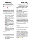
1
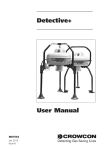
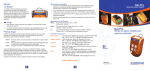
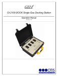
Crowcon C-Test User Manual Crowcon C-Test Gas (Bump) Test and Calibration Station For use with the Crowcon Clip and Clip+ Installation and Operation Manual Crowcon contacts: UK: 2 Blacklands Way, Abingdon Business Park, Abingdon, OXON, OX14 1DY +44 (0) 1235 557700 [email protected] US: 21 Kenton Lands Road, Erlanger, Kentucky 41018-1845 +1 859 957 1039 [email protected] NL: Vlambloem 129, 3068JG, Rotterdam +31 10 421 1232 [email protected] SG: Block 194 Pandan Loop, #06-20 Pantech Industrial Complex, Singapore, 128383 +65 6745 2936 [email protected] CN: Unit 316, Area 1, Tower B, Chuangxin Building, 12 Hongda North Road, Beijing Economic & Technological Development Area, Beijing, PRC 100176 +86 10 6787 0335 [email protected] www.crowcon.com / www.crowcon.us Issue 1 - June 2012 Page 1 Crowcon C-Test User Manual READ FIRST BEFORE OPERATION Do not use the C-Test if it appears to be damaged. Inspect prior to each use. Ensure the C-Test is used with certified calibration gas matching the configured concentrations. DO NOT use expired calibration gas. Please check the expiration date located on the bottle. Only operate the C-Test in non hazardous areas with adequate ventilation and ensure the exhaust is suitably attached. Confirm that the gas cylinder contains enough gas for testing procedures before starting. Do not expose the C-Test to electrical or mechanical shocks before, during, or after use. Do not allow liquids to condense and / or use high power sprays on the C-Test. Crowcon recommends periodic back up of the data stored on the USB Memory. Read the entire C-Test manual and follow all instructions to ensure proper use and safe installation. The C-Test may not support all gases. Contents 1. Getting Started ............................................................................................................................... 3 1.1. Set Up / Installation instructions ............................................................................................... 3 1.2. Power ...................................................................................................................................... 3 1.3. Installation of Calibration Gas .................................................................................................. 3 2. Testing the Monitors ....................................................................................................................... 3 2.1. Indications ............................................................................................................................... 4 2.2. Documentation ........................................................................................................................ 4 2.3. Hibernation .............................................................................................................................. 4 3. Troubleshooting .............................................................................................................................. 4 4. Orientation ...................................................................................................................................... 5 5. Maintenance ................................................................................................................................... 5 6. Specification ................................................................................................................................... 5 7. Advanced ....................................................................................................................................... 6 7.1. Functionality ............................................................................................................................ 6 7.2. Retrieving data ........................................................................................................................ 6 7.3. Logs Folder ............................................................................................................................. 6 8. C-Test Manager Software User Guide ............................................................................................ 8 8.1. Software Installation ................................................................................................................ 8 8.2. Getting started ......................................................................................................................... 8 8.3. Connecting via IR Link ............................................................................................................. 8 8.4. Connecting via USB Disk ......................................................................................................... 8 8.5. Changing C-Test Settings ........................................................................................................ 9 8.6. Monitor Settings..................................................................................................................... 10 8.7. Log Settings .......................................................................................................................... 11 9. Warranty ....................................................................................................................................... 12 Issue 1 - June 2012 Page 2 Crowcon C-Test User Manual 1. Getting Started 1.1. Set Up / Installation instructions C-Test is designed to be used on a flat surface and can be mounted on either a desk or on the wall. Each C-Test should come with the following: 1. 2. 3. 4. 5. C-Test station Removable cylinder guide One (1) USB cover One (1) USB memory stick *Underneath the cover* One (1) Multi-region Power Supply Note: Calibration Gas cylinders are sold separately 1.2. Power C-Test is powered by an internal rechargeable battery. Only charge with the power supply provided. AC Power: Ensure the Power LED is green, insert the unit and press the bump test button Battery Power: Press the bump test or calibration button to activate the station. Pressing either button will immediately initiate a test. The unit should be inserted before pressing the button. Charging the Battery: While charging the Unit LED lights will cycle to indicate charging. Once fully charged, the Power LED will be solid green. If the battery is low, the Power LED will blink green. A complete charge takes approximately 3 hours. A full charge lasts for at least 1000 bump test cycles. 1.3. Installation of Calibration Gas In order to perform tests, a bottle of certified calibration gas in required. This section is located on the right hand side of the C-Test. To install, insert the bottle and screw until tight, once properly connected you will be able to view a pressure reading in the pressure gage. Crowcon recommends using standard 34ltr, 58ltr or 116ltr bottles. Below are the recommended calibration gas concentrations: H2S: 25 or 15 ppm CO: 100 ppm O2: 18% O2 concentration It is important to ensure the C-Test is set to the correct levels of gas. Warning: Calibration bottle pressure must be less than or equal to 1000 PSI. Pressures above 1000 PSI can damage the C-Test station. 2. Testing the Monitors Place the activated Crowcon Clip or Crowcon Clip+ monitor into the bay. Make sure that the calibration gas matches the unit type inserted. The C-Test can test different monitors by using a multi-gas blend calibration mix. To begin the test, press either the bump test button or the calibration button. A bump test will take approx twenty (20) seconds and a calibration will take one (1) minute and forty five (45) seconds. During the test, the light will display an ORANGE colour. Issue 1 - June 2012 Page 3 Crowcon C-Test User Manual 2.1. Indications No USB/USB Fail Indication: If the USB is properly installed the power light will remain solid during testing. A blinking power light during testing indicates either no USB or a USB failure. A blinking light also indicates the tests are not being recorded. Pass/Fail Indication: A successful test will result in a GREEN light; a failed test will result in a RED light. Once the Power button has displayed the final result (GREEN or RED) you can then remove the detectors. It is important to ensure that the ‘TEST’ light is not illuminated when removing the USB in order to view data. 2.2. Documentation During the test, both the bump test records and the event log of each unit will be downloaded to the onboard USB memory. For more detailed information please refer to the Advanced section of this manual. 2.3. Hibernation C-Test has the ability to hibernate the Crowcon Clip+ monitor. To use this feature, power on the C-Test, place the monitor in the bay, press and hold down the bump test button and calibration button at the same time for 2 seconds. All lights will turn orange and the power light will blink. Once complete, the CTest lights will turn green for a successful hibernation and red for a failure. Please do not remove the detectors until the power light turns green. Note; during this process the event logs of the monitor are automatically transmitted to the USB in the C-Test. Hibernating will erase the event log on the monitor. 3. Troubleshooting If a monitor has failed a bump test make sure to check the following: Check to see if any excessive dirt/debris has entered into either the sensor cavity or audible alarm cavity. If so make sure to clear these before testing Check to see if any excessive dirt/debris has accumulated over the small IR communication window located on the top of the monitor parallel to the top light bar Check the calibration gas level. 58L bottles are “full” at 500 PSI: 116L at 1000 PSI Make sure the C-Test station is not placed directly in very bright light. Very bright light can interfere with communication of the detector Re-Try the unit. If a monitor has failed three (3) times please contact Crowcon or your local service agent Issue 1 - June 2012 Page 4 Crowcon C-Test User Manual 4. Orientation C-Test Components: 1 2 3 4 5 6 7 8 9 Charging Port Calibration Gas Port Gas Exhaust Outlet IR Communication Window Test Activation Buttons Pressure Gage USB Memory Cover Power and Test LED’s Monitor Bay 5. Maintenance The C-Test Station should be examined before and after use to ensure that all components are in operating order and undamaged. Ensure that the gas cylinder has adequate gas for testing purposes. Examine monitor bay to ensure that each opening is free and clear of debris. Examine the AC power module and ensure it is undamaged and firmly connected. If/When needed clean the C-Test with a soft non-static cloth. 6. Specification Size: H 212 x W 275 x D 122 mm (8.3 x 10.8 x 4.8 inches) Warranty: 1 Year Battery Type: Rechargeable Lithium Ion Memory: USB-2 GB Standard (Note: larger memory capacity can be used) Tests Performed: Bump Test and Calibration Information Stored: Bump/Calibration Logs, Individual monitor Event Logs, Monitor and C-Test Firmware, and Unit Configurations Configuration: Unit settings (configuration and firmware) can be programmed/upgraded via the C-Test. Gases Available: H2S, CO, and O2 Unit Compatibility: Works only with Crowcon Clip and Crowcon Clip+ monitors Calibration Gas: Compatible with 34l, 58L or 116L bottles; An accessory is available to allow use of larger gas cylinders, contact Crowcon or your local service agent for details. Issue 1 - June 2012 Page 5 Crowcon C-Test User Manual 7. Advanced This section contains instructions for advanced features of the C-Test station: 7.1. Accessing the detector bump logs and event logs Configuration programming for both the monitors and C-Test Firmware programming for both the monitors and C-Test Functionality The table below details the functionality available C-Test Manager Functionality Manual USB Retrieve event logs and bump test logs Retrieve event logs and bump test logs Program configuration files for both monitors and C-Test Upload Firmware Upgrades for both monitors and C-Test For more information about C-Test Manager, please refer to Section 8. 7.2. Retrieving data The section below will cover retrieving data manually by removing the USB from the C-Test and inserting it into a computer: Once you have manually accessed the USB through a computer you will see up to 3 folders: Logs, Firmware, and Config. When accessing the USB directly only the Logs folder will apply, use caution when accessing other folders as they contain files that can only be changed through the C-Test Manager Software. Caution: Do not delete any files from the USB prior to saving them; the C-Test does not store this information internally outside of the USB. 7.3. Logs Folder The C-Test is designed to automatically collect the results of each bump test for each monitor. In addition, it will download the detector event log. All detector event logs will be stored in the folder labelled ‘CC’ and all test logs will be stored in the ‘TS’ folder. Each time a detector is tested it will transmit the entire event log up to 25 events to the USB memory. These events are saved as individual logs. It will be common for a monitor to have multiple event log files stored on the USB. Individual event logs will be organized inside the Clip folder by the serial number. The serial number format is in the form of PGYY123456 (where P=Product code, G=gas type, YY=year, and 123456 is the 6-digit serial number). The logs will be stored in logs / CC / PGYY / (serial / 512) / [fullserial#] Every bump test and calibration performed on the C-Test is stored into the file named TS-CC.csv, inside the TS-CC folder. This file follows a specific format so that it can later be parsed into a database or Excel format for further manipulation and storage. You can then access the CSV file containing the test results. There are multiple lines in every test report. We will illustrate how to read this report line by line. Issue 1 - June 2012 Page 6 Crowcon C-Test User Manual The first line is for the C-Test and the overall results for each test: Date: Date and Time of Test Test: Type of Test (Calibration, Bump Test, Turn Off (for Clip+ only) C-Test: Model Number Serial Number: Individual serial number for C-Test station Overall Result: Pass/Fail C-Test F/W version: C-Test station firmware version C-Test H/W version: C-Test station hardware version Location: This field can be programmed via the C-Test Manager program to show a location for the C-Test. The second line and third lines are unique to each monitor and will appear for each test: Detector: Crowcon Clip or Crowcon Clip+ Serial: Serial Number for each detector Result: Pass/Fail Unit F/W Version: Firmware version of the individual monitor Audio: Pass/Fail Visual: We do not test the visual alarm during the test; this will always display an X. Visual alarms can be verified with the daily self test. Num Sensors: Number of sensors in the instrument, this should always display 1 Show Sensor Readings, Bump Flash Disabled, and Hide Clock: True if enabled; False if not enabled User ID: Unique programmable 6 digit number Self Test Interval: Default is 20 hours; this option can be changed via IR Link or via C-Test Manager The Third line(s) are for each sensor on the monitor. Sensor: Sensor Type (H2S, CO, or O2) Result: Pass/Fail Reading: Peak unit reading during the test in ppm Bottle Lot #, Bottle Expiry: Both fields can be programmed via C-Test Manager Bottle Concentration: Default settings can be found and programmed via C-Test Manager High Alarm, Low Alarm: Alarm settings of the individual monitor Calibration Interval and Bump Test Interval: Intervals of the individual monitor Bump Test Due and Calibration Test Due: Number of days unit scheduled test is due Issue 1 - June 2012 Page 7 Crowcon C-Test User Manual C-Test Manager Software User Guide 7.4. Software Installation The C-Test Manager software is included on the USB memory stick supplied with the station. Up to date software can be requested from your local service agent, Crowcon regional office or is available for download on www.crowcon.com in the Crowcon Clip product page. This software will work with Windows versions XP, Vista, and Windows 7. 7.5. Getting started C-Test Manager interacts with the C-Test either via IR Link or by USB stick. The software allows the retrieval of test logs, Crowcon Clip & Crowcon Clip+ event logs, program configurations, and managers to perform firmware upgrades. Below are detailed instructions for how to use the software: 7.6. Connecting via IR Link Open C-Test Manager and plug in the IR Link to your computer. Then power on your C-Test. Place the IR Link in the monitor bay. Once it is placed correctly, make sure that the IR button is selected and click “Read”. A successful connection will result in a green bar in the lower right hand corner. Please note that the IR Link will only talk to the C-Test when in the ‘ON’ state. This requires the power light to be illuminated. This can be achieved by pressing either button when no monitor is in the monitor bay. 7.7. Connecting via USB Disk Remove the USB Disk from the C-Test (the USB Disk is located underneath the USB memory cover). To remove the cover, please use 2mm Allen key. Place the USB Drive into your computer; make sure the USB Disk button in selected and click “Read”. A successful connection will result in a green bar in the lower right hand corner. Issue 1 - June 2012 Page 8 Crowcon C-Test User Manual 7.8. Changing C-Test Settings Default Settings: Once you successfully communicate with the C-Test, you will see that the unit comes programmed with a number of default settings. Unless necessary we do not advise changing the following fields: Number of Event Logs Maximum bump time Location customisation: This field can be used to assign a unique name to the docking station. This will appear on the test log file. Ex: “Gate 3 C-Test” Auto Power-Off Time: After performing a test the unit will power off after 120 seconds, if you wish for the docking station to stay on longer, you can change this field. Gas Bottle Fields: Users can program in detailed information about their calibration gas. Expiration Date and Bottle Lot # will appear on each test record. If the expiration date is set to today’s date, that field will remain blank on the test record. Testing Check Boxes: Changing any of these fields may disable key testing functions, please ensure these actions are understood before changing any of the pre-set values. Allow Calibrations – Allows a calibration if the Calibration button is pressed Allow Bump Tests - Allows a bump test if the Bump button is pressed Allow Hibernate – Allows the hibernation functionality described in section 2.3 Allow Configurations – Allows automatic change of configuration during test Allow Firmware Upgrades – Allows automatic firmware update of all monitors presented Auto cal after Bump fail – Allows a calibration to run should a monitor fail and bump test Firmware upgrade: The C-Test allows for firmware upgrades to occur during the lifetime of the unit. These may be product improvements to add additional features or to enhance monitor performance. Most firmware upgrades are not required unless notified by Crowcon. After you have made your requested changes click on the Write Device Button. If a successful write has occurred you will see a green bar at the bottom (see above). Issue 1 - June 2012 Page 9 Crowcon C-Test User Manual 7.9. Monitor Settings Users can program Crowcon Clip & Clip+ configurations for each sensor type. Once this configuration has been programmed to the C-Test, every monitor that is bump tested will take on the new configuration values. In order to make changes to any particular field please update the value and ensure the check box on the left hand side is checked. Below is a description of the individual fields: User ID: Each individual unit can now have a unique electronic user ID. You are able to program in up to 6 characters. Note: Some alphabetic characters do not display well. Calibration Interval: In order to help with Calibration test accountability users can adjust the Calibration Interval to company requirements. If a unit has not been Calibrated within the time frame the unit will prompt the user to run a Calibration via the C-Test. Bump Interval: In order to help with bump test accountability users can adjust the Bump Interval. If a unit has not been bump tested within the time frame the unit will emit a flash until it has been tested either manually or via the C-Test. Self Test Interval: By default all Crowcon Clip & Clip+ instruments have a default 20 hour self test. Frequency can be set anywhere from 8 to 20 hours. High Alarm/Low Alarm Set Points: Adjust the high/low alarm set point. Note: When doing so make sure to set the alarm limit not to exceed the local or site guidelines. Some sites may have different set points than others. Show Sensor Readings: Once the unit starts to see gas the unit will display the real time reading with a 0.1 ppm resolution. If this is unchecked the unit will always display the life remaining or flash low/high alarm in an alarm condition Hide bump due LED Flashing: If you prefer to not have the units flash when due for a bump test, please make sure to check this box. Hide Clock: This will turn the monitor into a real time ppm display monitor. By default always showing a real time ppm reading. After you have made your requested changes click on the Write Device Button. If a successful write has occurred you will see a green bar at the bottom (see above). Firmware updates: The C-Test allows for firmware upgrades to occur during the lifetime of the unit. These may be product improvements to add additional features or to enhance monitor performance. Most firmware upgrades are not required unless notified by Crowcon. Once new firmware has been programmed to the C-Test, units will be upgraded before testing. During the upgrade the LED lights will remain orange in colour and flash. DO NOT move the unit during a firmware upgrade. Issue 1 - June 2012 Page 10 Crowcon C-Test User Manual 7.10. Log Settings Test records as well as individual detector event logs can be accessed using C-Test Manager. Test records contain detailed dates and times for individual bump checks and calibrations. The test record is listed at the top of the page and starts with TS-CC_TS[serial Number]. Event logs are listed by serial number. The event log retrieved will be the 25 most recent events. Past events can be located by accessing the USB drive. Download the test file: Make sure to “Read” the IR or USB Drive. The Test file will automatically populate. Click the check box next to the test file and click “Read” again. A screen will prompt you to choose the location for where you want the file to be stored. By default these files are .csv and should be opened using Microsoft Excel. This will be the default location for both test files and event logs. If you want to change this location, right click next to the “Files” field. From there select “Set Local Destination”. How to download event logs: Make sure to “Read” the IR or USB Drive. All available units will be listed by serial numbers. To select the file(s) you want, click on the check box next to the desired units. Users can download multiple records at the same time. By default these files are .csv and should be opened using Microsoft Excel. Inventory File: To allow users to keep better track of their units, C-Test Manager can generate an inventory file. The inventory file is listed by serial number, unit ID, and gas type. Here are the steps to retrieve the inventory file: Right click next to the “Files” tab, and then select Set Inventory Filename. A screen will prompt you to choose the location where you want to save the file and file name. Return back to the C-Test Manager and click on the box next to TS-CC _[Serial Number], then click “Read” again. Then go to the specified location to find the inventory file. Issue 1 - June 2012 Page 11 Crowcon C-Test User Manual 8. Warranty Limited Warranty Crowcon warrants this product to be free from defects in material and workmanship under normal use and service for a period of one year beginning upon the date of delivery for all Crowcon C-Test monitors. This warranty extends only to the sale of new and unused products to the original buyer. Warranty Procedure To facilitate efficient processing of any claim, contact your local Crowcon agent/distributor, a Crowcon regional office or our global customer support team (English working language) on +44 (0)1235 557711 or [email protected] to obtain a returns form for identification and traceability purposes. This form may be downloaded from our website ‘crowconsupport.com’ and requires the following information: Your company name, contact name, phone number and email address. Description and quantity of goods being returned, including any accessories. Instrument serial number(s). Reason for return. Products will not be accepted for warranty without a Crowcon Returns Number (CRN). It is essential that the address label is securely attached to the outer packaging of the returned goods. The guarantee will be rendered invalid if the instrument is found to have been altered, incorrectly stored, modified, dismantled, tampered with, or has not used Crowcon spares for replacement parts including sensors) or has been serviced or repaired by any party not authorised and certified by Crowcon to do so. The warranty does not cover misuse or abuse of the unit including use outside of specified limits. Warranty Disclaimer Crowcon accept no liability for consequential or indirect loss or damage howsoever arising (including any loss or damage arising out of the use of the instrument) and all liability in respect of any third party is expressly excluded. This warranty does not cover the accuracy of the calibration of the unit or the cosmetic finish of the product. The unit must be maintained in accordance with the instructions in this manual. The warranty on replacement consumable items supplied under warranty to replace faulty items, will be limited to the unexpired warranty of the original supplied item. Crowcon reserves the right to determine a reduced warranty period, or decline a warranty period for any sensor supplied for use in an environment or for an application known to carry risk of degradation or damage to the sensor. Our liability in respect of defective equipment shall be limited to the obligations set out in the guarantee and any extended warranty, condition or statement, express or implied statutory or otherwise as to the merchantable quality of our equipment or its fitness for any particular purpose is excluded except as prohibited by statute. This guarantee shall not affect a customer’s statutory rights. Crowcon reserves the right to apply a handling and carriage charge whereby units returned as faulty, are found to require only normal calibration or servicing, which the customer then declines to proceed with. For warranty and technical support enquiries please contact: Customer Support Tel: +44 (0) 1235 557711 Fax: +44 (0) 1235 557722 Email: [email protected] Issue 1 - June 2012 Page 12