1
User's Manual for TB118 V2.2
Preface
Welcome to use Our Injection Molding Machine Control System
Safety Cautions
(Please read it before installation)
1.In order to ensure the secure operation of the whole system in case of
the abnormal external power and the control system's failing to function,
please set up the external safe circuit for the control system.
Danger 2.Upon its failure to detect the abnormal conditions of input and output,
the control system cannot control the output. Therefore, please design
the external circuit and frameworkto ensure the safe operation of the system.
1.Please read this User's Guidance carefully before installation.
2.Do not dismantle the host computer shell and keyboard without permission.
Cautions 3. In case of any questions, please dial the after-service service hotline
of PORCHESON.
Note
1. With the constant upgrading and improvement of the system,the changes
in the relevant information and technical parameters will not be informed
in advance.
2. If there is deficiency in this manual, please do not hesitate to give your
comments and suggestions.
R
1
User's Manual for TB118 V2.2
Preface
Statement
Please read the manual carefully before you use this
system. PORCHESON Company will only be responsible
for the maintenance of the problems exist in the system
itself, and will not be responsible for the fault caused by
improper operation, unauthorized maintenance,natural
disasters, or the system damage or data loss caused by
other abnormal situations. The changes in the manual will
not be informed in advance. The contents in the manual
are for reference,the company will not be responsible.
for thelosses caused by the misunderstanding of the
manual.There may be differences between the actual
objects and the abstract image,but the functions are
Consistent.
According to the Copyright Law, the Companyowns
and retains the exclusive ownership of all works,without
thewritten approval of the Company,any deletion, revision,
reproduction or imitation of the manual are not permitted.
R
2
Contents
User's Manual for TB118 V2.2
PORCHESON TECHNOLOGY CO.,LTD
T B 11 8
System Configuration &
Installation
1
Button Operation
specification
5
Operator's Manual
2 0 0 9 . 0 7 Version
Explanation of the Param
eter/Function Setting
12
Production management
35
Explanation of the System
Debugging and Setting
41
Input/output State
Detection
55
Reference & Appendices
63
All copyrights are reserved, any duplication without the prior authorization shall be
forbidden.
R
3
User's Manual for TB118 V2.2
Contents
Contents
Chapter 1 System Configuration & Installation
1. System Configuration & Remarks
p6
2. Features of the PS860AM Control System
p6
3. Installation and Debugging of Computer Control System
p7
Chapter 2 Specifications of the Button-Pressed Operations
1. Figure of Keyboard of the Operation Panel (See the figure below)
p10
2. Explanation of the Functional Keys
p11
3. Explanation of the Parameter Setting button
p12
4. Cursor Key
p12
5.Operation Mode Selection Key
p13
6. Electrothermal ON/OFF key and Motor ON/OFF key
p13
7. Manual Operation Keys
p14
8. Setting Scope of Numeric Items
p16
Chapter 3: Descriptions on setting parameters/functions
1. The main control panel shown while turning on
2 Setting for celerity information
p17
.
P21
3 Setting for mould close information
p22
4. Set mould opening information
p23
5. Set the plastic injecting information
p24
6. Set the pressure retaining information
p25
7. Set plastic melting/drawing/cooling information
p26
8. Set the stuff auto-clearing up information
p27
9. Set the table information
p28
10. Set the mould adjusting information
p29
11. Set the ejecting forward information
p30
12. Set loose core information
p31
13. Set the air blow information
p32
14. Set time/count information
p33
15. Set temperature information
p34
16. Set warm-up and chart of observation information
p35
17. Set Module information
.
18. Amend note information
P36
.
19. special parameter adjustmetn Setting
.
R
4
P37
P38
User's Manual for TB118 V2.2
Contents
Chapter 4 production management
1. Set porduction Imformation
p40
2. SPC Track Note Page
p41
3. Pressure/Speed curve Setting Page
p42
4. Temperature Track curve Page
p43
5. Alarm note
p44
6. USB Setting Page
p45
Chapter 5 Instructions for the System Commissioning Settings
1. Engineer Setting Page
p46
2. Delay Setting Page
p47
3. Pressure/Flow Slope Setting Page
p48
4. Pressure Pre-Adjustment Page
p49
5. Flow Pre-Adjustment Page
p50
6. Back Pressure Pre-Adjustment Page
p51
7. Electronic Ruler/ Pressure Setting Inspection Page
p52
8. Special Function Options Page
p53
9. Standby Function Setting Page
. P56
10. Programmable Standby Function Page
..
P57
11. Temperature Parameter
..
P58
12. Machine No./ Production-Factory Value Setting Page
Chapter 6 Input/Output Mode Inspection
1. Input Inspection Page
2. Key inspection Page
3. Output Inspection Page
p59
p60
p62
p63
Reference & Appendices
1. Tb118 keyboard installation dimension Layout
2. Tc118 keyboard installation dimension Layout
3. external dimensions and installation hole positions drawings for power supply case
and transformer
p66
p67
4. Exterior dimensions and installation hole position drawings for main controller
p68
5. system wiring drawing
p69
6. Motor heating wiring drawing
7.Common Interference Suppression Method
p70
p71
R
5
p68
Chapter 1 System Configuration & Installation
User's Manual for TB118 V2.2
Chapter 1 System Configuration & Installation
1. System Configuration & Remarks
No.
1 Host Computer
2 Keyboard
Content
Code
P S6 6 0 A M
P S8 6 0 A M
2 4/ 24 + 9 + 3 Electronic Ruler
2 7/ 28 + 10+3 Electronic Ruler
T B 1 18 (colour) " 800* 4 80
1 6: 9 7 in ch / TFT
TC118(Colour ) " 800* 4 80
1 6: 9 7 in ch / TFT
3.Power pack P W6 0 0 B
6 00 W
4.Message cable D B- 1 5 F
1 T o 8 me te r o pt io nal
Q'ty Remarks
1 Set
Optional
1 Set
1 Set
Optional
1 Set
1 Set
1 Set
2. Characteristics of PS860AM Control System
The whole computer may control all functions and temperatures.
The system has bright LCD display and 800*480 7inch? concolorous/colorful (optional)
The system adopts two CPU design with fast operating speed, precise control and high stability.
The control host computer adopts the blocking design with time-saving installation and rapid
maintenance.
It has the real time function to display time and date in real time.
With 999 groups of mode data storage, it may enter the model description and real-time operating
help in Chinese and English.
The cipher setting and data locking can prevent the operators from changing the established data
arbitrarily to influence the quality of products.
There are multiple languages for your choice that display dynamically in real time.
Packing modulus setting function for 6-digit output may set the packing modulus.
Various self-plugging and tein type programs are applicable for the self-plugging and tein control
in different types.
Ejector nozzle temperature can be controlled with open or enclosed loop.
PID (Proportional Integral Derivative) with self temperature control has (6+1) sections of temperatures.
Temperature may be preset a week in advance to enable more convenient operation.
Various types of Glue Shot ways, 4 sections of Glue Shot and class-3 pressure preservation
Failure Self-detection functions, alarm display and voice prompt
Input and output are done by the optically coupled circuit to isolate the interference of the
external circuitry.
The output value of pressure, speed, current can have real-time dynamic observation,
and it is not necessary to install another ammeter
In the inspection window, you can inspect all input and output points and the moving states of key.
3-circuit standard D/A proportion output with max. current as 3A
Presetting of the voltage and runoff values, proportional valve available for the products in all
brands and better linear proportion.
R
6
Chapter 1 System Configuration & Installation
User's Manual for TB118 V2.2
3. Installation and Debugging of Computer Control System
3.1Cautions upon Installing the Control System
The design of control system is simple and easy, only one 15-core shielding cable connecting the
keyboard and host computer shell with flexible and handy installation and connection. The sketch map
for installation is shown as follows:
R S 2 3 2通 信 口
C AN_ BUS 1 C AN_ BUS 2
Control
system.
POWER
Strong
eletricity
Equipment
Strong
eletricity
Equipment
Strong
eletricity
Equipment
+5 V( 3 A)
+ 24 V( 3 A)
+ 24 V( 8 A)
+ 38 V( 3 A)
R U N系统运行
0
1
2
3
4
5
6
7
0
1
2
3
4
5
6
7
0
1
2
3
4
5
6
7
0
1
2
+
1
2
3
-
2
2
2
+
+
+
+
+
+
+
+
+24V
X 0 0 安全门前
X 0 1 马达起动毕
X 0 2 射胶保护罩
X 0 3 锁模停止
X 0 4 电眼输入
X 0 5 熔胶转速
X 0 6 射台前停
X 0 7 射台后停
XCOM
X 1 0 备用
X 1 1 备用
X 1 2 顶退保护板
X 1 3 顶针前停*
X 1 4 顶针退停*
X 1 5 安全门后
X 1 6 备用
X 1 7 备用
XCOM
X 2 0 微调齿数
X 2 1 调模前停
X 2 2 调模后停
X 2 3 机械手合模
X 2 4 机械手顶针
X 2 5 入芯A停止
X 2 6 出芯A停止
X 2 7 马达故障
XCOM
X 3 0 入芯B停止
X 3 1 出芯B停止
压力 P
速度 S
背压 F
备用 Y 7 3
备用 Y 7 2
母模吹气 Y 7 1
公模吹气 Y 7 0
YCOM
出芯B Y 6 7
入芯B Y 6 6
出芯A Y 6 5
入芯A Y 6 4
开模缓冲 Y 6 3
中 泵 Y62
大 泵 Y61
故障警号 Y 6 0
YCOM
高压锁模 Y 5 7
低压锁模 Y 5 6
塑机顶进完 Y 5 5
塑机开模完 Y 5 4
调模向后 Y 5 3
差动锁模 Y 5 2
调模向前 Y 5 1
顶 退 Y50
YCOM
顶 进 Y47
开 模 Y46
座 退 Y45
抽 胶 Y44
熔 胶 Y43
射 胶 Y42
座 进 Y41
锁 模 Y40
X 3 2 缺油报警
+2 4 V
压
锁模
力
射胶
检
系统
测
ADG
锁模
电
射胶
子
尺
顶针
+1 0 V
-
K 6 油温
-
K 5 五段
-
K 4 四段
-
K 3 三段
-
K 2 二段
-
K 1 一段
-
K 0 射咀
-
+
+
-
3
2
1
0
7
P W6 00 B
PO WE R
6
5
4
3
2
1
0
7
6
5
4
3
2
1
0
7
6
5
4
3
2
1
0
火线 L 1 2
M
11
Y
10
9
OIL
8
T5
7
T4
6
T3
5
T2
4
T1
3
T0
2
零线 N 1
Relay
board
PORCHESON
PS860AM
Ebb eletricity section
Strong eletricity section
control box equipment outfit (for reference only)
(1)Upon installing the host control box, adopt the enclosed distribution cabinet at the first choice. It
shall be fixed in the well-ventilized, greaseproof and dustproof conditions equipped with a fan and
dustproof. The distribution box shall be stored under 50?.
(2)Upon fixing the host computer and power pack, please keep the interconnecting parts such as all
AC connectors and transformers as far away from each other as possible to prevent the electric
wave interference from the electronic grid.
(3)All electric wires and shielding wires shall not be cut off, lengthened or curtailed arbitrarily. You
should use the electric wires and shielding wires provided by this company to prevent from
influencing the reliability and normal operation of the control system.
(4)The shell of flame couple shall adopt the shielding wire. When the outer shielding of all flame
couples adopts the thermal couple reticles, the reticle and machines shall be well grounded and
connected to the ground with the earthing resistance below 10Ω.
(5)Upon wiring, separate the high and low pressure line from the computer control line as much as
possible, do not bind all electrical wires together to prevent the interference from affecting the
reliable operation of control system.
(6)Upon fixing the keyboard and 15-core communication connections of the host computer, you shall
press and tweak with force to prevent the poor connection from affecting the reliable operation of
control system.
(7)Pay special attention to the oil valve outlet public port YCOM, it shall be connected well to prevent
the computer from inputting while having the phenomenon of oil valve having no motion.
R
7
Chapter 1 System Configuration & Installation
User's Manual for TB118 V2.2
3.2Inspection of the Control System
(1)After installation completed, carry out an overall inspection if all connection lines are well fixed
including the switching power supply, host computer shell, electrothermal output line and the
thermal couple of keyboard, etc.
(2)After the line inspection completed, carry out an electric connection inspection. First take out the
11-digital output line plug of the DC power supply outlet port, namely the power pack, and then
power on to examine and measure if the voltage is the same as the nominal values and observe if
the output indicator on the power pack is normal.
(3)Power off after the measurement completed, insert the DC power supply to input to the plug of
host computer shell. After power-on again for inspection, LCD on the keyboard will display the
normal state of the main page. Revolve on the emergency stop switch to check if the RUN indicator
on the host computer shell turns on. When it turns on, it indicates that the system can work soundly.
3.3gging of the Control System
1
(1)After the system having shown normal operating state, press
to adjust color and comparison.
STU
button on the monitor page
资 料
(2)To conduct the parameter setting and memory testing, press
DATUM
入
module numbers and then set data in all screens. Press 输
ENTER
button to select a group of
button to save data. Disconnect
the power and connect it again after a few time, the system will automatically call the data of
module numbers saved by you. In case of they are correct, it indicates that the memory is all right.
(3)Afterwards, set the data in all relevant data (please see Chapter III Explanation of the Parameter
Setting for the detailed operations). Upon setting in the first time, set the pressure and speed as little
as possible and then after all movements come normally, gradually increase the values to normal
parameters to prevent from damaging the mechanical performances.
(4)After all parameter set, save them and carefully inspect if all input and output points are normal.
Carry out an overall inspection of the alarm system, including the front and back safety doors. The
wire of safety doors shall be connected as stated in the following figure.
LS4
LS2
LS3
LS1
R
8
Chapter 1 System Configuration & Installation
User's Manual for TB118 V2.2
X CO M
L S1
LS2
X 00
XC OM
X0 0
L S3
L S4
X CO M
X 15
LS4
LS2
LS3
LS1
LS1
XC OM
L S3
X0 1
XC OM
LS 2
X1 5
XCO M
LS 4
X16
PS860AM
★Safety Doors * Special Explanation:
When X00=ON/X15=OFF orX00=OFF/X15=ON closing/opening the doors, or in case of other
abnormal conditions, the system will issue an alarm 2 seconds later for Safety Door Failure and
simultaneously terminate all operating output. In the semi-automatic mode, the condition foropening/
closing the safety doors is that the time from LS1, LS2, LS3, LS4 all turn [OFF] to all turn [ON] is
more than 0.5 as valid in order to prevent the twitter of safety door switches from causing
error operation.
R
9
Chapter 2 Explanation of the Key Operations
User's Manual for TB118 V2.2
Chapter 2 Explanation of the Key Operations
1. Figure of Keyboard on the Operation Panel (See the figure below)
R
10
Chapter 2 Explanation of the Key Operations
User's Manual for TB118 V2.2
2. Explanation of the Functional Keys
Keys
开锁模
M.PLT
射 出
INJECTION
储 料
FEEDING
座台/调模
NOZZ/ADJ.
Usage
Enter into the screen to set the mold opening & locking movement
Enter into the screen to set the Glue Shot and pressure-preserving
movement
Enter into the screen to set the feeding, glue taking and automatic
material removal movement
Enter into the screen to set the nozzle and model adjustment
托 模/中 子
EJE/CORE
Enter into the screen to set ejector, self-plugging and huff.
时 间
TIME
Enter into the screen to set timing and counting.
温 度
TEMP.
资 料
DATUM
快速设定
Enter into the screen to set temperature and pre-heating.
Enter into the screen to set the changes to mold and production
facilities.
Enter into setting celerity one 、 two setting page
CELERITY SET
监 视
MONITOR
Return to the monitor screen in any time.
帮 助
?
HELP
The on-line help screen upon entering into the current state.
R
11
Chapter 2 Explanation of the Key Operations
User's Manual for TB118 V2.2
Keys
Usage
PC连接
Enter into the screen to set USB
PC LINK
诊 断
Enter into the screen to set alarm
DIAGNOSE
曲 线
Enter into the screen to Speed and Temperature Track curve
CURVE
生产管理
Enter into the screen to Setting porduction Imformation and SPC
Track Note
FLOW CHART
3. Explanation of the Parameter Setting
7
8
4
5
6
1
2
3
清 除
0
ABC
JKL
STU
CLEAR
DEF
MNO
VWX
9
GHI
PQR
YZ
[ ]/ -.
0-9 numeric keys are used for data input in the data
setting screen. When the electric lock is in “OFF” state,
these ten numbers are locked to ensure the data will not
be changed arbitrarily. In the meanwhile, there are 26
English letters and special symbols respectively on 0-1
numeric keys used for the input of Chinese and English
letters as well as the machine serial number. [DELETE]
key is used to delete the error words during entering the
parameters and serial numbers. [INPUT] key is used to
select the functions during function selection and used to
confirm during item confirmation.
R
12
Chapter 2 Explanation of the Key Operations
User's Manual for TB118 V2.2
4. Cursor Key
Keys
Usage
Skip key, pressing it will skip the cursor to the upper line
Escape key, pressing it will move the cursor to the left
Escape key, pressing it will move the cursor to the right
Skip key, pressing it will skip the cursor to the lower line
5.Operation Mode Selection Key
Keys
Usage
Remarks
手 动
MANUAL
半自动
SEMI.AUTO
电眼自动
SENR.AUTO
时间自动
TIME.AUTO
Pressing this key will enter the system
into manual state.
There is an indicator on the left
upper of all keys. Pressing any key
will turn on this indicator, indicating
the system is in this state. Every time
Pressing this key will enter the system the computer is started, the default
into semi-automatic operation
state of system is manual operation.
In case of the temperature has not
reached the set value, the system is
impossible to perform semi-automatic 、
Pressing this key will enter the system senr-automatic and time automatic
into senr-automatic operation
operations. The indicator will not turn
on when the semi-automatic 、senrautomatic and time automaticoperation
key pressed till thetemperature reaches
Pressing this key will enter the system
the set value.
into time-automatic operation
R
13
Chapter 2 Explanation of the Key Operations
User's Manual for TB118 V2.2
马达开/关
电热开/关
6. Electrothermal ON/OFF key
and Motor ON/OFF key
HEATER ON/OFF
MOTOR ON/OFF
In the manual mode, press the key once and the indicator at the left upper will turn on, indicating
thefunction state has opened. Pressing the key again and this indicator will turn off, indicating the
function state has shut off. Repeatedly pressing this key, the functions will turn on or off in turn.
Upon the emergency switch stops, the motor will power off swiftly without affecting the electro
thermal operation.
7. Manual Operation Keys
Keys
Usage
Operation Conditions
开 模
MOLD OPEN
锁 模
Model-opening
operations
Mold-locking
operating
MOLD CLOSE
射 出
Glue Shot Operation1
INJECT
射 退
Decom pression
SUCK BACK
1.Normal safety door input;
2.Ejector retracts till bumping;
3.Mold has not locked to the termination position;
4.The signals (mold-locking) of robot hands have been
connected when the robot hands are selected.
1.In case of time glue shot selected, the injection time has not completed;
2.In case of the position selected, it has not reached the glue-shot
termination position;
3.Temperatures within all sections of material canister shall no texceed
the leeway scope (without temperature alarm)
1. When the electronic ruler is off duty, the time for launching
back is inadequate;
2. When the electronic ruler is on duty, the position for launching
out is inadequate;
3. The actual temperature of the reel has to be in the setup scope
(no temperature alarm) and the time for cold start of the screw
is adequate;
Ejection advance
operation1
1. Mode opening has come to the terminate position;
2. The neutron withdrawal limit has been connected and the time
for withdrawal of neutron is adequate; (when select neutron)
3. Mechanical hand signals (tray mode) has been connected
( when select mechanical hand);
4. When the electronic ruler is on duty, the position of tray mode
has not reached the terminal position;
5. When the electronic ruler is off duty, ① choose the trip: has not
reached the stop position. ②choose the time: the time calculation
of tray mode is not adequate;
Liftoff operation
1. When the electronic ruler is on duty, the position of tray mode
has not reached the terminal position;
2. When the electronic ruler is off duty, ① choose the trip: has
notreached the stop position. ②choose the time: the time
calculation of tray mode is not adequate;
托模进
EJECT ADV.
托模退
EJECT RET.
1. The model has not opened to the termination position.
R
14
User's Manual for TB118 V2.2
Keys
Chapter 2 Explanation of the Key Operations
Usage
储 料
Operation Conditions
Feeding Operation
1.Feeding has not come to the termination position;
2.Temperatures within all sections of material canister shall not
exceed the leeway scope (without temperature alarm)
Automatic Material Rem
oval Operation
1.Selection and use of automatic material removal;
2.Times of automatic material removal not completed;
3.Temperatures within all sections of material canister shall not
exceed the leeway scope (without temper ature alarm)
Several Items Operation
1.The operating conditions are the same as those for ejection
advance and liftoff;
2.The time of ejector setting has not completed.
CHARGE
自动清料
AUTO PURGE
多次托模
EJECTOR
润 滑
Lubricating Pump Work
1.Lubricate total time hav e no en d
LUBR.
公模吹气
Male Mold Huff Operation
1.Selection and usage of male mold huff;
2.The time of male mold huff has not completed.
AIR BLST. MOV.
母模吹气
Female Mold Huff
Operation
1.Selection and usage of female mold huff;
2.The time of female mold huff has not completed
AIR BLST. STN.
座台进
Nozzle advance operation
NOZZLE ADV.
1. When the block limit selection is off duty, there is no conditions;
2. When the block limit selection is on duty, ① the lock mode stops
ON. ② Has not reached the block stop position; b. the time
calculation of the block is not enough;
座台退
Nozzle backward operation
1、No condition;
Mold-adjusting Selection
1. If transfers mode by hand, press this button in the manual state,
the indication light will be on, that means you can transfer mode
by hand;
2. If automatically transfers mode, press the button twice in the
manual state, and the indication light will be on, that means
you can conduct automatic transfer of mode;
Mold-Adjusting
Backward Operation
1. Ente r the state of manual mode transfer;
2.The mold-adjusting retract has not come to the termination position.
NOZZLE RET.
调 模
MOLD ADJ.
调模退
MOLD THICK
R
15
User's Manual for TB118 V2.2
Keys
Chapter 2 Explanation of the Key Operations
调模进
MOLD THIN
Mold-Adjusting
ForwardOperation
中子A进
A
CORE A IN
中子A退
A
CORE A OUT
中子B进
B
CORE B IN
中子B退
B
CORE B OUT
Operation Conditions
Usage
Chip-insertion
Operation A
Chip-Extraction
Operation A
Chip-insertion
Operation B
Chip-Extraction
Operation B
1.To select the mold-adjusting use state;
2.The mold-adjusting advance has not come
to the termination position.
1.Selection and usage of Self-plugging A;
2.Chip-insertion A has not come to the termination
position or the time has not completed;
3.Liftoff has reaches its position or the liftoff time
has come.
1.Selection and usage of Self-plugging A;
2.Chip-insertion A has not come to the termination
position or the time has not completed;
3.Liftoff has reaches its position or the
liftoff time has come.
1.Selection and usage of Self-plugging B;
2.Chip-insertion B has not come to the termination
position or the time has not completed;
3.Liftoff has reaches its position or the liftoff time
has come.
1.Selection and usage of Self-plugging B;
2.Chip-insertion B has not come to the termination
position or the time has not completed;
3.Liftoff has reaches its position or the liftoff time
has come.
8. Setting Scope of Numeric Items
Number
Setting Items
Setting Scope
Unit
1
Time Setting
Digital ≤600.00
Second
2
Pressure Setting
Digital≤160.0
Bar
3
Speed Setting
Digital≤99.9
%
4
Back Pressure
Digital ≤160.0
Bar
5
Temperature Setting
Digital ≤999.9(Measure)
Digital ≤600.0(set)
℃
6
Storage of Mold Data
Digital ≤999
Number
7
Predicted Turnout
Digital ≤99999999
PC
In case of the set values exceed the above-mentioned scopes, the system will not accept the numbers
set and keep the original set values. For the habit of data input, the data input of this system is display from
right to left.
R
16
User's Manual for TB118 V2.2
Chapter 3: Descriptions on setting parameters/functions
Chapter 3: Descriptions on setting parameters/functions
1. The Main Control panel while turning on
Connect with power, turn the red urgent stop switches, the operation light of the computer-RUN
-flickers, the following menu shown on the display, now the control system is running and it is ready to
operate the machine.
监 视
Press MONITOR
key at any time after re-turning on the computer, and then enter the menu of
the monitor menu of the machine. This menu is for monitoring temperature and machine running
condition.The names and numbers of the moulds will be set in mould information menu. The
temperature scale and current oil temperature show the real value of each stage thus its information
cannot be modified. Each function of the menus is described as follows:
The descriptions on mode:
Meanings
Mode
Motor is running
Electrical heating opened
Lubricator is lubricating.
The lubricator unsuccessful unchin
R
17
User's Manual for TB118 V2.2
Chapter 3: Descriptions on setting parameters/functions
The descriptions on display:
Display
Manual
Meanings and descriptions
The running mode of the machine;
Injection Nozzle
This section is heating;
Mould number
The current mould number;
Movable mould
Shows the current position of the mould. The unit: mm;
Screw
Shows the current position of the screw. The unit: mm;
Thimble
Shows the current position of the thimble. The unit: mm;
Pressure
The set pressure value of the current movement;
Flux
The set flux value of the current movement;
Prepare mold number
The nu mber o f mode openi ng of th e curre nt mod e of th e predi cted productio n;
Output
Set
Record the numbers of mould opening for current mould number during the
automatic operation of the system;
The time value and counter data of the current movement;
Operation
When a time value set for current movement, only the operation time increase
to the set time, the next movement starts. When it is the number was set, the
acted numbers will be shown on the display till the numbers reach the set counter
date.;
Whole process
The real operation cycle time of the system;
In low temperature
When the actual temperature is not in the scope of setup scope, it will
display the abnormal state of the current temperature in each area;
The Luo pole turns soon
Th e numb er of rotation of the screw i n one m inute (unit: R PM);
R
18
User's Manual for TB118 V2.2
Chapter 3: Descriptions on setting parameters/functions
Descriptions on alarm mode
Source
Solution
Exits unclosed
The mode locking stops and “xits
unclosed” showed if you operate
mode locking while exits unclosed;
Check if the switches of the front andrear exits
are correctly connected with input interface
of X00 、X01 and X15、X16 andcheck ifthey
can be pressed normally.
Open Exits
In “Semi auto” mode, the exits
remain unopened while a single
cycle ended ;
Open the exits, take out the products,
close exits and than continue the processing。
Failure of sensor
inspection
In automatic operation, when the
inspecting sensor is not “ ON”
after thimble withdrawing in sensor
cycling mode and the mid-time is
over, it warns “Failure of sensor
inspection”;
Remove the failure of Ejecting forward
and Ejecting backward and judge if there
are any long cover. The connection lines
and the sensor itself should be mainly
inspected when the light of X04input
point always shines.
Mould opening not fixed
When eject forward manually, the
mould opening not reach the position
of stopping mould opening;
Re-operate unlocking, or check position of
lock opening. ① When the electronic ruler
is on duty, check the number at the position.
②When the electronic ruler is offduty, check
whether X12is connected.
Clamping and open
mould notfixed on time
Clamping and open mould not
completed within “ the time
limitation of themould opening
or closing”;
Check the clamping and open mould
process,extend properly “the time
limitationof the mould opening or
clamping” if it is normal.
Alarm
It will warn if it has not turned into
Low pressure mould
high pressure when the low-pressure
protecting time is over time is over.
Check the mould, extend properlyhe
low pressure time” if there is not any
redundant objects.
Failure of Exit
Alarm when there is only one press
in X00 、X01and X15 、X16;
Check if the switches of the front andrear
exits are correctly connected withinput
interface of X00、 X01 and X15、X16
andcheck if they can be pressed normally.
Plastic melting not
completed on time
Plastic melting not completed within
“ the time limitation of plastic
melting”;
Check the plastic melting process and
find out if the plastic in plastic drum
has been run out. Extend properly
“the time limitation of plastic melting”
if it is normal.
Failure of plastic injection
The plastic injection testing stroke
switches X20 has not been pressed
or the electronic ruler has not
reached the plastic injection testing
point during plastic injection.
Check plastic injection process and
adjust the deviation value of plastic
injection testing
Failure of motor
Alarm when signal inputs motor
protection point X16.
Check if there is a protection on the oil
hydraulic motor caused by relay against
overload.
Cycle time is over
When Auto production cycle time
is longer than set [cycle time]
Check the auto production process,
extend properly the set [cycle time] if
it is normal.
R
19
User's Manual for TB118 V2.2
Chapter 3: Descriptions on setting parameters/functions
Alarm
Source
Solution
Knockout core A not
completed.
Knockout core B not
completed.
Machine has chosen knockout core
A and B. It requires that the knockout
space of the knockout core must have
been connected when eject forward
or multi-eject forward;
Check if the stop switches of the knockout
core A and B are connected correctly and
if they can be pressed normally. Set a stop
mode in function menu for knockout core
A and B when you do not use the knockout
core function.
The machine stops when the output
stopping machine function started or
The set output reached
the numbers of mould opening have
reached the set output number.
Solution: If you need the machine continues
running after the output reached, just set the
[ stop after alarm] in production menu as
[ out]; or reset the total mould openingof the
current mould number .
Descriptions on operation/prompt mode
Source
Alarm
High temperature in 1,2,3, The real temperature related to the stage of the machine hopper is higher
4,5, stages Injection nuzzle. than the set top limited value. (Maximum temperature values =the setup temperature value+ the setup maximumvalue).
The real temperature related to the stage of the machine hopper is lower
Low temperature in 1,2,3,
4,5, stages Injection nuzzle. than the set down limited value. (he set down limited value = thesetup temperaturevalue - thesetup maximumvalue).
Temperature short circuit n
1,2,3, 4,5, stages Injection
nuzzle
Auto stuff clearing up
completed
Auto mould adjusting
completed
Auto mould adjusting
not completed
The real temperature related to the stage of the machine hopper is higher
than the set top limited value.
After the set number movement completed and while auto stuff clearing
up.
Auto mould adjusting completed when using mould auto adjusting.
Auto mould adjusting not completed when using mould auto adjusting.
Enter manual mode first
When operate manual keys in auto mode.
Functions not selected
Certain function has not been selected when manual operate its keys.
Start motor
Next cycle Prepared
Sensor prepared
Exit mould adjusting
mode first
Enter mould adjusting
mode first
How to select motor: Prompt when the semi-auto/auto keys are pressed,
as the motor has not been started.
In auto mode, the mid-time between completing a cycle and starting
next cycle.
The mid-time has not been reached after withdrawing thimbles during
auto sensor cycling.
When operate non-[adjust forward, backward and auto mould adjusting]
keys in mould adjusting mode.
When operate [adjust forward, backward and auto mould adjusting] keys
in non-mould- adjusting mode.
R
20
User's Manual for TB118 V2.2
Chapter 3: Descriptions on setting parameters/functions
2.Setting for celerity information
快速设定
Press
CELERITY SET
key, enter the menu for setting celerity one information, now the menu is as following:
快速设定
Press
CELERITY SET
key twice, enter the menu for setting celerity two information, now as following:
Quick setting 1 and 2 menus are parameters cluster menus common used by jet moulding
machines.These two menus can provide important parameters needed daily adjustment by
machines, including:mould clamping, mould open, injection, hold pressure, plasticization,
ejector forward .
R
21
User's Manual for TB118 V2.2
Chapter 3: Descriptions on setting parameters/functions
3. Set mouId close information
开锁模
Press
M.PLT
key, enter the menu for setting mould close, now the menu is as following:
Descriptions on setting parameters/ process/function mode
L ow
Pres
Flux
Qui c
20
20
Sl o w
50
80
20
30
508.8
109 .0
H. Pr
12 0
25
2.0
(1). Process: while mould close, enter slow clamping first, and than enter fast clamping when the stroke arrives at
[508.8], and than enter low pressure clamping when stroke runs another [109.0], andthan enter high pressure
clamping when stroke runs another [2.0] till clamping completed. Italarms[low pressure mould protection time
is over] when the low pressure time is over but not enterthe high pressure yet
(2 ). Slow mode locking : when the dy namic mode e lectron ic ruler is [off duty], the tim e for slow loc k of the mode .
(3). Low pressure protection: Set a smaller low-pressure time for mould close, it is best to be fitting, otherwise,
the mould can not be protected.
(4). Time limitat ion to mold open and close: time limitation to mold open and close,pl ease set it longer,
and it is better to be fi tting, otherwise, the system alarms [mold open/close not completed on time].
(5). Differential mould close: press input keys to select [on] or[off], output when select [on] for quick mould close
Y52, not output when select [off] for quick mould close Y52,
R
22
User's Manual for TB118 V2.2
Chapter 3: Descriptions on setting parameters/functions
4. Set mouId opening information
Press
开锁模
key twice, enter the menu for setting mould opening, now the menu is as following:
M.PLT
Descriptions on setting parameters/ process/function mode
A ct io n
P re s
F lu x
P la ce
l ow
45
20
6 00. 0
M id dl e
Q ui ck
60
70
40
80
2 15 . 5
55 0.8
Slo w
20
20
50 .5
(1). Process: while mould opening, enter slow mould opening first, and than switches to quick mould
opening when stroke arrives at 50.5mm, and than switches to middle speed mould opening when
arrives at 215.5mm, and than switches to low speed mould opening when arrives at 550.8mm, and
than mould opening completed when arrives at 600mm
(2). Slow mode opening: when the dynamic mode electronic ruler is [on duty], the time for slow
opening of the mode.
(3). Time limitation to mould opening and clamping: time limitation to mould opening and clamping,
please set it longer, and it is better to be fitting, otherwise, the system alarms [mould opening/clamping
not completed on time].
(4). The function of manipulator: if a manipulator needed, please select [on] for it. After [on]
selected, the machine will output manipulator signal while mould opening comp leted.
Before mould close, the next cycle starts only after receiving the manipulator signal, and
stop the output of it at the same time.
R
23
User's Manual for TB118 V2.2
Chapter 3: Descriptions on setting parameters/functions
5. Set the plastic injecting information
射 出
Press
INJECTION
key once, enter the m enu for setting plastic injection, now the menu is as following:
Descriptions on setting parameters/ process/function mode
5 Seg
4 Seg
3Se g
2S eg
1 Seg
1 25
1 10
30
1 10
20
Fl u x
95
90
20
8 0
40
Place 0.00
5.00
20.00
70.00
120.00
(1). Process: while plastic injecting, 1 stage injects plastic first, and than switches to 2
stage when arrives at 220.0mm, and than switches to 3 stage when arrives at 150.9mm,
and than switches to 4 stage when arrives at 98.5mm, and than switch to pressure
retaining when arrives at 10.0mm
(2). The whole process of plastic injecting; monitor the normal plastic injecting process.
Equal time arrives when start plastic injecting ---start timingand switch to pressure re
taining whatever the arrives the distance or not. Thus the injecting time should be set
longer than real time.
Pr e s
(3). Ejection models: ① when the screw electronic ruler is on duty, you can choose [position]
or [time]. a. If you select [position], the ejection will be pressure keeping through the position
of the electronic ruler; b. If you select [time], the ejection will be pressure keeping through
time. ② when the screw electronic ruler is off duty, you can select [trip] or [time]. a. If you
select [trip], the ejection will be pressure keeping through trip; b. If you select [time], the
ejection will be pressure keeping through time.
R
24
User's Manual for TB118 V2.2
Chapter 3: Descriptions on setting parameters/functions
6. Set the pressure retaining information
射 出
Press INJECTION key twice, enter the menu for setting pressure retaining, now the
menu is as following:
Descriptions on setting parameters/ process/function mode
5Se g P r e s
4Le v
P r es
Flux
Time
20
35
50
55
20 25
35
20
1.00 1.10
50
35
4 Lev 3L ev 2Le v 1 L ev
3Le v
2 Le v
1Le v
1 25 .9
55
20
( The function of slope )
2.59 1.25
(1). Process: when enter pressure retaining after injecting, enter the1 stgrade pressure of pressure retaining
and speed movement first, and than [the 1 stgrade time is over] enters the 2 nd grade of pressure retaining,
and than enter the 3 rd grade pressure retaining through [the 2 nd grade pressure retaining is over], and than
switches to plastic melting delay after [the 3 rd grade pressure retaining is over]
st
(2). How to use: it will be controlled as following when only 1 pressure retaining control is needed for
st
molding condition: key the 1 pressure retaining time in the box of 1 st grade time, pressure retaining
2nd time [0.00, it is 0 when (out)], pressure retaining 3 rd time [ 0.00, it is 0 when (out)].
(3). The function of slope: Controlling on pressure is for retaining pressure or change of slope. Refer
to the set menu, the real output pressure is as the picture above right.
(4). Ejection test: you can select [on duty] or [off duty], when you select on duty, in the mode of
half/full automation, computer will get the average value 20-100 mode ejection ends as the
ejection test point. Users can set up the permitted error value scope on the pressure keeping
page. If surpass the setup mode number, and if it is under the test scope or over the test, you
will hear the alarm [the ejection is failed], at the same time, the production management will
regard it as the defect.
R
25
User's Manual for TB118 V2.2
Chapter 3: Descriptions on setting parameters/functions
7. Set plastic melting/drawing/cooling information
储 料
Press
FEEDING
key once, enter the menu for setting plastic melting/drawing/cooling,
now the menu is as following:
Descriptions on setting parameters/ process/function mode
A ctio n
F.Tk
Mel1
Mel2
B.Tk
Pres
Bya
30
120
15
80
20
50
Flux
25
85
20
43
Place
20.0
150.0
220.0
350.0
(1). Process: After retaining pressure, front drawing first, switches to melting 1 when arrives at 20.0mm,
and than switches to melting 2 when arrives at 150.0mm, and than switches to back drawing
when arrives at 220.0mm, and than plastic melting completed when arrives at 350.0mm.
(2). Time limitation to plastic melting: the time for monitoring no-stuff. The uncompleted plastic melting
will be taken as no-stuff when time is over. So set the time limitation longer than real plastic melting
time, otherwise it alarms [plastic melting not completed on time].
(3). Cooling time: In auto mode, cooling time stars just after plastic injecting pressure retaining. The
time for plastic melting and drawing is a part of cooling time. When the process time is longer than
cooling time, the cooling time is over. Mould can be opened only after plastic melting/drawing
completed. Otherwise mould will be opened as soon as the cooling time is over.
R
26
User's Manual for TB118 V2.2
Chapter 3: Descriptions on setting parameters/functions
8. Set the stuff auto-clearing up information
储 料
Press
FEEDING
key twice, enter the menu for setting stuff auto-clearing up, now the
menu is as following:
Descriptions on setting parameters/ process/function mode
I nje
[On]
Melt
Take
Times of stuff clearing up ?
[Yes]
END
(1). Process: How to use the stuff auto-clearing up function. In manual mode, press the key of stuff
auto-clearing up, the system starts the stuff auto-clearing up process, first is the process of with
drawing, and than cycles automatically according with process shown in the diagram above.
(2) Times of stuff clearing up: the times of repeating plastic melting and injecting.
(3). Automatic cleaning of materials: Select On Duty, press the [automatic clearing of materials]
button to clear the materials.
(4). Material restoring time: when it automatically operates, and after the block finishes, start to
operate the storage materials, the time accounted returns the ejection movements.
R
27
User's Manual for TB118 V2.2
Chapter 3: Descriptions on setting parameters/functions
9. Set the table information
座台/调模
Press
NOZZ/ADJ.
key once, enter the menu for setting table, now the menu is as following:
Descriptions on setting parameters/ process/function mode
(1). Block's slow motion: ① when the electronic ruler is off duty, the block will encounter the
block stop switch [X06] and then will be inserted into the block slow motion and die com
bination. The time accounting stops when come to the block. ② when the electronic ruler
is on duty, the speed of the block is controlled by electronic ruler. (Function: to prevent crash
and to protect the service life of die.)
(2). Auto table:[off], [plastic melting completed]or[cooling completed] can be selected.
If [plastic melting completed] is selected, withdrawing after plastic melting complete
d in auto mode.
(3). Block termination methods: ① When the electronic ruler is off duty, you can select [trip] or
[time], if you select trip, the automatic block withdrawal will retreat to the back of the block
and stop at the location of [X07] switch control; if you select time, the withdrawal of autom
atic block will be controlled by the setup time. ② when the electronic ruler is on duty, select
[position] or [time], if you select position, the withdrawal of automatic block will be controlled
by the position of the electronic ruler; if you select time, the withdrawal of automatic block
will be controlled by the setup time. (Note: in the state of manual state, press [block back]
button, the movement of block withdrawal will not be limited)
R
28
User's Manual for TB118 V2.2
Chapter 3: Descriptions on setting parameters/functions
10. Set the mould adjusting information
座台/调模
Press
NOZZ/ADJ.
key twice, enter th menu for setting mould adjusting, now the menu is as
following:
Descriptions on setting parameters/ process/function mode
(1). How to adjust mould: [Manual] or [Auto] can be selected, the pressure for mould adjusting is about
20-50 bar, the speed is 30-60%.
(3). Fine adjusting mode: [Time] or [gear number] can be selected. Select [time] if the machine is not
mounted with sensor; the initial value is controlled by [time]; select [gear number] if there is a sensor,
the initial value is controlled by [gear number].
(3). The time of mould closing: In auto mould adjusting, time limitation for mould closing.
(4). How to use auto mould adjusting: Select [auto] for mould adjusting, press the keysof [mould
adjusting] and [auto mould adjusting], and than enter the mode of auto mould adjusting as soon as
the exit shut. The movement pressure and flux of adjusting forward and backward in the process of
auto mould adjusting is controlled by a set value in the fine adjusting box. The sound of can be
heard and [mould adjusting completed] shown after the mould adjusting completed.
(5). While adjust mould manually or automatically, the forward time of mould adjusting is controlled by
stop limit .
R
29
User's Manual for TB118 V2.2
Chapter 3: Descriptions on setting parameters/functions
11. Set the ejecting forward information
Press
托模/中子
EJE/CORE
key once, enter the menu for setting ejector forward, now the menu is as following:
Descriptions on setting parameters/ process/function mode
(1). Times fixed : [Ejecting forward] → [Ejecting backward stop] as a cycle, move in according to times.
(2) Vibrating: [ ejecting forward stop] → [ejecting forward stop, off] as a cycle, the movements are set in
according to the times of the ejecting forward. The ejecting backward movement ends when times
finished.
(3) forward retaining: Used in semi-auto. Stops while ejecting forward movement reach its limits, and not
ejecting backward until before closing mould in next cycle.
(4). backward delaying: after ejecting forward and backward completed, the ejecting backward movement
occurs while the set time delayed.
(5). forward delaying: after mould opening completed, the ejecting forward movement occurs while the
set time delayed.
(6). Retaining function: if the retaining time is set as 00, there is no retaining function. The retaining
function is for retaining pressure, speed and starting retaining time for the output after ejecting forward
completed. The retaining movement is completed as soon as the time is over.
(7) [Note]: A. when do manual mode holding, the number will no be limited. (if do manual
repeated mode holding, the number will be limited) B. If you set the number of mode holding
at 0, the function of mode holding can not be on duty.
R
30
User's Manual for TB118 V2.2
Chapter 3: Descriptions on setting parameters/functions
12. Set loose core information
Press
托模 /中子
EJE/CORE
key twice, enter the menu for setting loose core, now the menu is as following:
Descriptions on setting parameters/function mode
(1) Core starting: there are [stroke] and [position] for options. Choosing [stroke], then it will be
controlled by stroke setting values; choosing [position] then it will be controlled by position
setting values
(2) The function of loose core A: [On] or [Off] can be selected.
(3). The function of loose core B: [On] or [Off] can be selected.
(4). Mode A. [Time], [stroke] and [count] can be selected. If [time] selected, set the time till the
movement of loose core A terminated; if [stroke] selected, the movement of loose core will not
terminate until the stop signal [X25, X26] of input point shows ON; if [count] selected, pipe thread
control can be taken, and the movement termination is decided by the number of pipe tread pulse
inputted through [X25, X26]. `
(5). Mode B: [Time], [stroke] and [count] can be selected. If [time] selected, set the time till the
movement of loose core B terminated; if [stroke] selected, the movement of loose core will not
terminate until the stop signal [X30, X30] of input point shows ON; if [count] selected, pipe thread
control can be taken, and the movement termination is decided by the number of pipe tread pulse inp
utted through [X30, X31].
(6). Time/gear number: Time or gear number can be set in this box, when [time] is selected for loose
core A and B, the set value in the box is time. When [count] is selected for loose core A and B, the
set value in the box is gear number.
(7). Start the trip: the neutron start the position of movement (neutron in: [before lock the mode],
[before the low pressure], [before the high pressure] and [the lock mode stops]; neutron out:
[before the mode opening] [before the middle speed], [before the low speed] and [the mode
opening stops]), that is, where the template is moving, setup the action of neutron A and B.
(8). Start position: The position for starting the movement of core knock in or knock outwhere the mould
stops-- is a set value for the movement of core loose A and B.
R
31
User's Manual for TB118 V2.2
Chapter 3: Descriptions on setting parameters/functions
13. Set the air blow information
托 模/中子
Press EJE/CORE key thrice, enter the menu for setting air blow information, now the menu
is as following:
Descriptions on setting parameters/function mode
(1) Why blowing air: This function can be used in the stamping mould that need air blow.
(2). Time delay: Delay first when arrives automatically at the position of air blow, and than blow air
when delay time starts.
(3). Start the trip: you can select[before the mode opening] or [after the mode opening] to set
the value of blowing.
(4) Starting position: [Pre-mould opening] can be selected. [Pre-mould opening] is taken as a set value
for the movement of air blow.
(5). Function mode: [On] or [Off] can be selected, no movement of air blow if [Off] is selected.
Mould end,delay count
Blow Male
Mould end,delay count
Blow Female
R
32
User's Manual for TB118 V2.2
Chapter 3: Descriptions on setting parameters/functions
14. Set time/count information
时 间
Press
TIME
key thrice, enter the menu for setting time/count, now the menu is as following:
Description on setting parameters
(1). Lubricating modulus: Count mould opening times. The oil pump starts when mould opening times
reach the set value.
(2). Total time for Lubrication: the total time spent in this lubrication.
(3). the output of the repeated operation with the total time for lubricatin.
(4). The interval of the repeated operation with the total time for lubricatin.
(5). Wait Cycle time: During auto process, it is the time between completed thimble movement and
starting a movement of moulds clamping of next cycle.
(6). Cycle time: The time limitation to operation cycle in automatic process. The system alarms [cycle
time is over] when the real operating time is longer than cycle time limitation.
(7). Movement time limitation: the max time permitted when output movement.
(8). Error alarm bell: The max time when error output occurs. To avoid long time alarming, the bell stops
alarm when time is over
(9).during the output time of lubrication, if it fails to detect any lubrication pressure signal, it would
trigger an alarm, telling that the lubrication is failing. If “opping working ” after the failing of
lubrication is chosen, then it would stop lubricating and would change to work in manual mode and
stop the engine after the cycle of the alarming.
Out
LubricG
LubricTT
R
33
User's Manual for TB118 V2.2
Chapter 3: Descriptions on setting parameters/functions
15. Set temperature information
温 度
Press
TEMP.
key, enter the menu for setting temperature, now the menu is as following:
Description on setting parameters
The set temperature value is 0.1 ℃( Celsius). The temperature of the hopper of injection molding machine is close-loop
controlled after it is fed back to controlling system by K style thermal electric couple.
The system provides total 6 stages of temperature control and 1 stage oil temperature testing. [Open-loop] /[close-loop]
can be selected to control temperature for injection nozzle. The system monitors the temperature in every area to find out if the
temperature overpasses the set top and bottom limitation. It cannot inject or melt plastic if the temperature is lower than the
bottom limitation and than the cold preventing screw starts. It alarms when the temperature is higher than the top limitation.
The temperature of each stage is shown on the main menu
Half temperature f unctions: sele ct use, at this time, th e temp erature setup value is half o f the c urrent showed setup value.
Cold boot: A fter th e boot, the actual tem peratu re in e ach area will b e within the setup sc ope.
部 分 塑 胶 密 度 与 料 管 加 热 温 度 参 考 资 料
原料简名
密度
加热温度º C
原料简名
密度
加热温度º C
A.B.S
1.01-1.05
190-270
PMMA
1.17-1.20
180-260
PS
1.05
190-240
PPO
1.08-1.09
260-330
A.S
1.06-1.07
180-250
PA/NYLON
1.08-1.17
230-290
H.P.S
L.P.S
1.05-1.08
0.91-0.93
220-280
150-260
NYLON66
PVC/S
1.03-1.15
1.20-1.40
280-330
150-180
H.P.E
0.94-0.96
190-260
PVC/H
1.30-1.58
160-200
P.P
0.98-0.90
200-290
P.E.T
1.38-1.41
280-310
P.C
1.2-1.22
280-320
P.T
1.41-1.52
220-280
P.O.M
1.41-1.42
190-230
R
34
User's Manual for TB118 V2.2
Chapter 3: Descriptions on setting parameters/functions
16. Set warm-up information
温 度
Press
TEMP.
key twice, enter the menu for setting warm-up, now the menu is as following:
温 度
Press
TEMP.
key third, enter the menu for setting chart of observation, now the menu is as following:
Description on setting parameters
Warm-up function: Can set a time for seven days a week in advance. The system controls the
heating system to heat through the set value of the intraday [on]/[off] time. The system heats
automatically the hopper to working temperature before operator comes to the office. The operator's
waiting time for heating hopper is decreased.
*[note]: The input value of time adopts the input value of 24 hours system. 00:00 is 12: 00 Midnight.
R
35
User's Manual for TB118 V2.2
Chapter 3: Descriptions on setting parameters/functions
17. Set mould information
资 料
Press
DATUM
key, enter the menu for setting mould, now the menu is as following:
Description on setting parameters
(1). Mould number: this system can store 10 mould numbers. The system can provide automatically the
information of the modified mould number after they have been modified.
(2). How to store mould: Move cursor to the box of mould numbers, key in the mould number; and than
move the cursor to the box of the name of the mould, key in the name of the mould; this system
provides the input modes with English/Chinese phonetic alphabet; move the cursor to box of storage
after the name has been keyed in and than press [enter] to store the name.
(3). How to get mould: Move cursor to the box of mould numbers, key in the mould number that will be
read out, move the cursor to the box of reading out, press [enter] to read out. The functions of getting
mould is limited within manual mode to prevent accident occurs; in the semi-auto/ auto mode, the
accident is caused by the influence of bad products, which comes from the sudden varying of the set
parameters in the menu.
(4). How to delete: Move cursor to box of mould number, key in the mould number that will be deleted,
and than move the cursor the box of deleting, press the [enter] to delete. The current mould number
can not be deleted.
(5). How to check mould: Move cursor to the box of mould browsing, read it through the rolling menu
by using up and down key.
R
36
User's Manual for TB118 V2.2
Chapter 3: Descriptions on setting parameters/functions
18. Amend note information
资 料
Press
DATUM
key twice, enter the menu for amend note information, now the menu is as following:
Description on setting parameters
(1). Page number: This screen can keep at most 999 items of records, press _____ or______,
press buttons to move up an down cursor to view the revised information.
(2) Printing: start printing function.
R
37
User's Manual for TB118 V2.2
Chapter 3: Descriptions on setting parameters/functions
19. Set special parameters
Press
1
STU
key in the home menu, enter the menu for setting special parameters,
now the menu is as following:
参 数 设 定说明
(2) Mid / big pump start: when the setup executive action flow value is bigger than the setup mid/big
pump flow output value, the mid/big pump output point will have output.
(3) Move the cursor to select the [special parameters>>] button, press the input button, a new page
will pop up. At this time, the screen displays as follows:
R
38
User's Manual for TB118 V2.2
Chapter 3: Descriptions on setting parameters/functions
(3a) Adjustment of LCD contrast: move the cursor to this place, input the data [adjustment range
"1-31"]. Under appropriate brightness, the higher the contrast is, the richer the color will be
(Note: when LCD is the STN screen, it can be valid).
(3b) LCD brightness adjustment: move the cursor to this place, input the data [adjustment range
"0-100%"], the screen will display the darkness & brightness degree according to the data entered.
(3c) LCD color setup: the system can provide [normal/anti-color] two options, move your cursor
to this place, press [input] button to select LCD color display.
(3a) LCD backlight time: the system has the function of screen protection, the background light
time is adjustable, the setup scope is 1 6 minutes. If the keyboard is not pressed in the setup
time, the background light will be automatically turned OFF. (Note: if any button is pressed,
background light will be on)
(3e) Function of key sound: Select [use], you will hear a "tick" sound when the key is pressed, if
do not select, no sound.
(3f) Key sound scope: move your cursor to this place, input the data [scope "0-10"] to adjust voice
volume.
(3g) Correction of Touchscreen: click on the [Correction] button to enter the correction page
(Note: only if keyboard has the touch function, the correction can be valid)
(3h) Network connection status: the network connection status is indicated with colors.
(3i) Current IP: show the IP address of the machine.
(3j) Current connection state: show the network connection status: disconnect / connect.
(4) Move the cursor to select [language conversion>>] button, press the input button, a new page
will pop up. The screen displays as follows:
(4a) Language options: the system provides [language 1 / Language 2 / Language 3 /language 4 /
Language 5 / Language 6] the six language options, move the cursor to this place, press the
[input] button, you can carry out the conversion. (Note: the language categories of the system
can be set up by users)
R
39
User's Manual for TB118 V2.2
Chapter 4 production management
Chapter 4 production management
1. Set porduction Imformation
生 产管理
Press
FLOW CHART
key , enter the menu for setting production information, now the menu is as following:
FLOW CHART
Description on setting parameters
(1) The quality products equal to the number of the opened mould times the amount of one mould minus
rejects. The rejects are controlled through ejecting testing function. When ejecting testing function is
on, just like in stroke. When too much or too less stuff occurs, the rejects will increase amount value
of one mould, and [Failure of plastic] alarms.
(2). Set mould numbers: In the mould numbers setting of pre-production, the system starts alarming when
the number of mould opening arrives at the first 5 moulds till it reacheded The set output .
(3). Stop after alarming: [On] or [Off] can be selected. It will continue producing even arrives at the set
mould number if [Off] has been selected till an operator stops it.
(4). How to check production records: Move cursor to the box of production records, read it through the
rolling menu by using [↑↓] key.
R
40
User's Manual for TB118 V2.2
Chapter 4 production management
2. SPC Tracing record
生产 管理
Press
key 3 times to enter the SPC Tracing record with production management, and the
FLOW CHART
panel is as follows:
Description on setting parameters
(1). Pages: the panel has up to 999 pages, containing the consecutive information of the 999 modules. The
SPC Tracing record system can provide up to 9 important parameters of the latest 999 modules. The
operator can scroll up and down between page 1 and page 10 to manage the production of the modules.
By using the system, the operator will be able to have more insight of the actual variation of the
important parameters and take specific and proper actions to adjust the system's operation and improve
the quality of the product as a result.
(2). Print the page: the function would let the operator to make use of the printing service of the system.
(3). Intermittent cycle: record the data once every several cycles.
(4). Recording cycle: After entering automatic state, it will calculate from the first product,
when the product number is smaller than the data, the SPC tracking record will be valid.
R
41
User's Manual for TB118 V2.2
Chapter 4 production management
3. Pressure / Speed curve
曲 线
press the
key 5 times to enter the panel and it should be as follows:
CURVE
Description on setting parameters
(1). Display choice : the system can show you the selected curve, such as curve of injection, curve of
pressure for injection, pressure for pressure retention, pressure for locking the modules. All the
curves can be selected by the input key.
R
42
User's Manual for TB118 V2.2
Chapter 4 production management
4: Temperature tracing curve panel.
曲 线
Press
CURVE
key for 4 times to enter the temperature tracing curve panel, and it is as follows:
Description on setting parameters
(1). Display: That is to monitor the historic tracing curve of the temperature of a specific segment. For
reference , it can provide historic parameters of each segment, which are up to the past 6 hours. This
lets the operator more insight of the variation of the actual temperature and let compare and analyze
how the change of the temperature affects the quality of the products.
(2). Interval of the sample record: is the interval of the sampling process 5 minutes.
R
43
User's Manual for TB118 V2.2
5. Alarm note
Chapter 4 production management
page
诊 断
Press
DIAGNOSE
key one times to enter the alarm note page, and it is as follows:
Parameter setting introduction
(1). Display: the system stores at most 999 pieces of alarm records for inspection, it will be
helpful for the maintenance of the equipments.
(2). Printing list: start the function of printing list of the printer.
R
44
Chapter 4 production management
User's Manual for TB118 V2.2
6. USB setting page (for options)
PC连接
Press
PC LINK
button for one time; enter USB setting page. At this time the page shows as following:
Parameter setting introduction
(1) F o r mula downloading: download the mould data fromcontrol system of jet moulding
machine to the USB ofmoveable disc.
(2) F o r mula uploading: upload themould data from the USB of moveable disc to control
systemof jet moulding machine; at the same time the data will overlay previous data
correspondingly.
(3) System downloading: download themould data from control system of jet moulding machine
to the USB of moveable disc.
(4) System uploading: upload themould data from the USB of moveable disc to control system of
jet moulding machine; at the same time the data will overlay previous data correspondingly.
(5). Start/End D: when you are downloading the material of [formula] and [system], please
designate the scope of the downloading data ([formula]: 0~1999; [system]: 10000 ~ 10599).
(6). Mainframe replication: means updating the host procedures. First, press the stop button
on the keyboard, then move the cursor to [replication], press the enter button and move the
cursor to select [. Pin] files and update it.
(7). Update OPWIN.PS6: means updating the keyboard procedures. Move the cursor to [update],
press the enter button and move the cursor to select [. PS6] files and update it.
(8). Update the boot background documents: means updating the boot screen. Move the cursor
to [update], press the enter button and move the cursor to select [. Bmp] files and update it.
R
45
User's Manual for TB118 V2.2
Chapter 5 Instructions for the System Commissioning Settings
Chapter 5 Instructions for the System Commissioning Settings
1. Engineer Setting Page
Press
0
[ ]/-.
Keyon the Main Page to enter the Engineer Setting Page, and the following
will be displayed:
Enter the password * * * *. If correct,
will be displayed. If incorrect,
will be displayed.
If the password entered is correct, you can enter the system parameter setting page. It is not necessary
for the equipment end-user to adjust the system parameters. Please consult the equipment manufacturer
for any query. Any parameter adjustment disorder may result in damage to equipment capability,
unstable performance or failure to operate.
After the correct password is entered, the cursor jumps automatically to the first item from the
right. The cursorcan be moved to different items and then Key
correspondingpages. Alternatively, you can press the following keys
corresponding pages:
Key
Key
Entering Page
开锁模
M.PLT
射 出
托模/中子
<Delay Setting>
EJE/CORE
<Pressure/Flow Setting I>
时 间
INJECTION
<Pressure/Flow Setting II>
TIME
储 料
<Pressure Pre-Adjustment>
<Flow Pre-Adjustment>
温 度
FEEDING
座台/调模
NOZZ/ADJ.
TEMP.
资 料
<Special Function Options>
DATUM
R
46
is pressed to enter the
输 入
ENTER
to enter directly the
Entering Page
<Standby Function Setting>
<Programmable Standby
Points>
<Temperature Parameter/
Time Setting>
<Machine No./Ex-Factory
Value Setting>
User's Manual for TB118 V2.2
Chapter 5 Instructions for the System Commissioning Settings
2. Delay Setting Page
Entering Engineer Setting Page, press
开锁模
Key to enter the Delay Setting Page. The
M.PLT
following is displayed:
开锁模
Entering Engineer Setting Page,, press
The following is displayed:
Key twice to enter the Delay Setting Page.
M.PLT
Setting delay between actions
(1) The meaning of Start Delay: the
corresponding action valve ON→
(2) The meaning of End Delay: the
→
corresponding action valve
delay time T1 → pressure output ON
flow output ON
pressure output OFF
→ delay time T2→ action valve OFF
flow output OFF
R
47
User's Manual for TB118 V2.2
Chapter 5 Instructions for the System Commissioning Settings
3. Pressure/Flow Slope Setting Page
射 出
Entering Engineer Setting Page , , press Key
Slope Page I. The following is displayed:
Entering Engineer Setting Page , , press Key
Slope Page II. The following is displayed:
INJECTION
射 出
INJECTION
once to enter Pressure/Flow
twice to enter Pressure/Flow
Description on setting parameters
The Pressure/Flow Slope refers to the steep degree of rise or fall when the pressure/flow
changes from one value to the next value. "1.0攕 tands for the slowest change and "16.0攕 tands
for the fastest change. The setting range is [1.0-16.0].
R
48
User's Manual for TB118 V2.2
Chapter 5 Instructions for the System Commissioning Settings
4. Pressure Pre-Adjustment Page
Entering Engineer Setting Page, press
储 料
FEEDING Key
once to enter the Pressure Pre-Adjustment
Page. The following is displayed:
Description on setting parameters
The pressure pre-adjustment is the linear adjustment of pressure output. In general, the standard
pressure is 0-800mA and the standard output impedance is 10-20 Ω,unless the manufacturer has specific
requirements since different manufactures' overall oil piping designs and the capabilities of the pressure
proportional valve being used are different.
Pressure Adjustment Method:
The parameters on this page have been set before ex-factory. If the capability of the proportional valves
being used by the user is different, and the normal proportion and linear proportion cannot be achieved, the
parameters on this page can be adjusted. First set the pre-adjustment to be [Activated], and then set the
pre-adjustment item to be [ON]. For example, for the 50 bar pressure position of Item 50, if the reading on
the pressure meter is 45 bar, the parameter of this item should be increased until the pressuremeter reading
reaches 50 bar. Make adjustments on all parameters which need adjusting and make the0-140 bar pressures
being set correspond to the pressures being shown on the oil pressure meter respectively.After the adjustments
are completed, the computer executes automatically linear processing and takes theprocessing results as the
subsequent normal D/A proportional output values.
Initial data:
First, pre-adjust the needed maximum pressure data in 160bar, and then move the cursor to
[initial data], press the enter key and select [open], the system will automatically distribute
average data to 10bar---160bar.
R
49
User's Manual for TB118 V2.2
Chapter 5 Instructions for the System Commissioning Settings
5. Flow Pre-Adjustment Page
储 料
Entering Engineer Setting Page,, press Key
FEEDING
twice to enter the Flow Pre-Adjustment
Page. The following is displayed:
Description on setting parameters
The flow pre-adjustment is the linear adjustment of flow output. In general, the standard value
is 0-800mA and the output impedance is 40 Ω,unless the manufacturer has specific requirements since
different manufactures' overall oil piping designs and the capabilities of the pressure proportional valve
being used are different.
Flow Adjustment Method:
The parameters on this page have been set before ex-factory. If the capability of the proportional valves
being used by the user is different, and the normal proportion and linear proportion cannot be achieved, the
parameters on this page can be adjusted. As for the speed adjustment, different manufacturershave different
measuring methods. Some manufacturers use the melt tachometer to measure the rotation speed. First heat
the barrel until the barrel temperature reaches normal melt temperature. Set the melt speed to be 1, 10, 20, 30,
and more until 99 and check the actual values. Make adjustments on all parameters whichneed adjusting and
make the 0-99% speeds being set correspond to the proportional coefficients being shown on the tachometer
respectively. After the adjustments are completed, the computer executes automatically linear processing and
takes the processing results as the subsequent normal D/A proportional outputvalues.
Initial data:
First, pre-adjust the needed maximum flow data in 99%, and then move the cursor to [initial
data], press the enter key and select [open], the system will automatically distribute average
data to 10%---99%.
R
50
User's Manual for TB118 V2.2
Chapter 5 Instructions for the System Commissioning Settings
6. Back Pressure Pre-Adjustment Page
储 料
Entering Engineer Setting Page, press Key
Pre-Adjustment Page. The following is displayed:
three time to enter the Back Pressure
FEEDING
Description on setting parameters
The back pressure pre-adjustment is the linear adjustment of back pressure output. In general,
the standard pressure is 0-800mA and the standard output impedance is 10-20 Ω,unless the manufacturer
has specific requirements since different manufactures' overall oil piping designs and the capabilities of
the pressure proportional valve being used are different.
Back Pressure Adjustment Method:
The parameters on this page have been set before ex-factory. If the capability of the proportional
valves being used by the user is different, and the normal proportion and linear proportion cannot be
achieved, the parameters on this page can be adjusted. First heat the barrel until the barrel temperature
reaches normal melt temperature. Set the melt back pressure to be 1, 10, 20, 30, and more until 140 and
check the actual values. Make adjustments on all parameters which need adjusting and make the 0-140
bar back pressures being set correspond to the back pressures being shown on the back pressure meter
respectively. After the adjustments are completed, the computer executes automatically linear processing
and takes the processing results as the subsequent normal D/A proportional output values.
Initial data:
First, pre-adjust the needed maximum pressure data in 160bar, and then move the cursor to
[initial data], press the enter key and select [open], the system will automatically distribute
average data to 10bar---160bar.
R
51
User's Manual for TB118 V2.2
Chapter 5 Instructions for the System Commissioning Settings
7. Electronic Ruler Setting Page
Entering Engineer Setting Page, press Key
/ Pressure Setting Page. The following is displayed:
座台/调模
NOZZ/ADJ.
onec/twice times to enter the Electronic Ruler
Description on setting parameters
(1) Electronic Ruler Function: If the equipment needs to use the electronic ruler, choose [Activated].
If the equipment adopts stroke switch control, choose [Deactivated].
(2) Measurement Values: indicating the actual dynamic positions of the electronic rulers for theclamping
unit, the injection unit and the ejector.
(3) Total Length: referring to the actual lengths of the electronic rulers for the clamping unit, the injection
unit and the ejector.
(4) Limit Position: It refers to the maximum value set for the position. This parameter is subject to the
maximum position setting. For example, if the parameter set is bigger than the limit position value,
the system will not accept the parameter set and will retain the original setting.
(5) Zeroing: When the equipment choose [Activated] for the Electronic Ruler Function and uses the
electronic ruler, it may appear that the mechanic movement stroke is in place and yet the actual
positions of the electronic rulers for the clamping unit, the injection unit and the ejector do not
indicate "0". In such case, the corresponding ruler should be zeroed. Move the cursor to the zeroing
button for [clamping unit ruler], [injection unit ruler] and [ejector ruler], and then press 输ENTER入 Key
tomake zero clearing for the corresponding electronic ruler.
(6) Functions of sensors: setting process same as electronic ruler.
R
52
User's Manual for TB118 V2.2
Chapter 5 Instructions for the System Commissioning Settings
8. Special Function Options Page
托模 /中子
Entering Engineer Setting Page, press
EJE/CORE
Key to enter the Special Function Options Page.
The following is displayed:
Descriptions on setting parameters function mode
(1) Motor Idle Running & Automatic Stop: When [Activated] is chosen, time setting is effective and the
setting range is 1-99 minutes. If the equipment has no operation within the set time period after the
motor starts up, the motor is turned off automatically to protect the motor life and to save electricity
charge.
(2) Motor Y- Conversion: If [Activated] is chosen, the system converts from star output to delta output
when the motor starts up. The conversion time period can be set and the setting range is 2.0-99.9
seconds.
(3) Manual Base Advance Limit: If deactivated, the injection base advance is not subject to stroke control.
If activated, the injection base advance position is subject to the control of the limit switch X06.
(4) Mould Opening with Melt: If activated, the mould opening can be done as soon as the cooling time
expires, even if the melt has not finished taking out.
(5) Melt Key Locking: If activated, press the melt key once and then the melting continues and will stop
when the melt position is reached or the time expires. Or press the melt key once more to stop the
melting.
(6). Neutron beginning methods: select [trip] or [position], select [position] to set the position
value, and the movements when the dynamic mode arrives; select [trip], select the starting
movements from the four options of dynamic mode trip.
(7) Ejector Stop Type: [Stroke] or [Time] can be chosen. If [Stroke]is chosen, the stop is subject to the
stroke. If [Time] is chosen, the stop is subject to the set time.
(8) Mould Adjustment Activation: [Hydraulic] or [Electric] can be chosen. When [Hydraulic] is chosen,
mould adjustment pressure and speed do not participate in the mould adjustment job.
(9). Start to blow: select [position] or [trip], start the blowing work at the dynamic mode position
or the trip conditions in automatic state.
(10). Ejection total time: select [off duty] or [on duty], when you select off duty, it will eject the
pressure transfer condition trip or eject time; when you select on duty, it will eject the pressure
transfer condition trip or eject time or eject the total time.
R
53
User's Manual for TB118 V2.2
Chapter 5 Instructions for the System Commissioning Settings
托模/中子
Entering Engineer Setting Page, pressEJE/CORE Key to enter the Special Function Options Page.
The following is displayed:
Function parameter setting introduction
(1) Pressure/flux upper limit: the setting value in this page will lie on the upper limit range for
setting values of mould parameter in every page.
(2). Maximum temperature / percentage: the scope of maximum temperature setup value.
R
54
User's Manual for TB118 V2.2
Chapter 5 Instructions for the System Commissioning Settings
托模/中子
Entering Engineer Setting Page, press
Options Page.The following is displayed:
EJE/CORE
Key three times to enter the Special Function
Function parameter setting introduction
(1). Rotation speed of storage materials: when select [on duty], the screw rotation speed will be
displayed on the monitoring page, conversely, it will not be displayed.
(2). Gear number of single circle of storage materials: the gear number of one circle of gear screw.
(3). Electric heat restriction: select [on duty], the electric heat can not be started in the course
of motor starting.
(4). Function of intermittent lubrication: you can select [on duty] or [off duty], if select [off duty],
it will have continuous lubrication; if select [on duty], it will have intermittent lubrication.
(5). Maximum number of lubrication mode: The maximum number of lubrication mode, it is used
to control the lubrication cycle.
(6). Minimum time of lubrication: the minimum lubrication time.
(7). Output of insufficient oil restriction: select [on duty], when the X32 input time of insufficient
oil alarm reaches the setup value, it will give an alarm.
(8). Motor start delay: after the motor is started, you should delay the setup time, then you can
conduct manual or automatic operation.
R
55
User's Manual for Tb118 V2.2
Chapter 5 Instructions for the System Commissioning Settings
9. Standby Function Setting Page
时 间
After entering the correct password, press
Key to enter the Standby Function Setting
TIME
Page. The following is displayed:
Descriptions on setting parameters function mode
(1) Output Point Transfer Function: This function can be activated or deactivated. If activated, the output
point executes immediately transfer operation. In case that mal-function or damage occurs to a certain
point, the control can be transferred to another point by activating this function. For example, in case
that failure occurs to the mould opening output point and the knockout core function is deactivated, the
Y46 mould opening point can be transferred to Y66 and then the output wires should be exchanged.
The system is equipped with the function of simultaneously transferring two output points. Once this
function is activated, the system makes judgment on the two selected items. If the item is [ON], the
transfer of the pre-set conditions of the item will be executed.
(2) Input Point Transfer Function: This function can be activated or deactivated. If activated, the input
point executes immediately transfer operation. In case that mal-function or damage occurs to a certain
point, the control can be transferred to another point by activating this function. For example, in case
that failure occurs to the front safety door input point and the knockout core function is deactivated,
the X00 front safety door input point can be transferred to X25 and then the input wires should be
exchanged. The system is equipped with the function of simultaneously transferring two input points.
Once this function is activated, the system makes judgment on the two selected items. If the item is
[ON], the transfer of the pre-set conditions of the item will be executed.
R
56
User's Manual for TB118 V2.2
Chapter 5 Instructions for the System Commissioning Settings
8. Programmable Standby Function Page
时 间
After entering the correct password, press Key
TIME
to enter the Programmable Page.
The following is displayed:
Descriptions on setting parameters function mode
In order to meet diversified application needs and provide an innovative product, we take the initiative
to offer the programmable standby function page so that the users can define and revise by themselves
the functions and the action sequence.
Example 1: For a certain mould injection machine, due to the different design of the oil piping, it is
required that a point is output while clamping at high pressure and the power will not be interrupted until
the melt finishes taking out. To achieve such a special function, choose an item and have it activated,
and then specify an output point (i.e. this function is output through Y xx), and then set the action
sequence [CD].
Notes: Regarding the output scope of Sequence D Clamping Stop, in automatic mode, the clamping
switch is contacted during the process of mould close at high pressure, and this sequence output starts
until the melting finishes; in manual mode, the clamping switch is contacted during the process of mould
close at high pressure, and this sequence output starts until the mould opening key or the reset key is
pressed.
Example 2: For a certain mould injection machine, due to the different design of the oil piping, it
is required that a point is output while injecting and melting. To achieve such a special function, choose
an item and have it activated, and then specify an output point (i.e. this function is output through Y xx),
and then set the action sequence [FH].
R
57
User's Manual for TB118 V2.2
Chapter 5 Instructions for the System Commissioning Settings
11. Temperature Parameter/Time Setting Page
温 度
After entering the correct password, press Key
Setting Page. The following is displayed:
TEMP.
to enter the Temperature Parameter/Time
function Description on setting parameters
(1)Nozzle Function、Sequence I、Sequence Ii、Sequence III、Sequence Iv 、Sequence Vfunction 、
[Activated] or [Deactivated] can be chosen. If deactivated, the system will not execute inspection
and control on this sequence.
(2)Oil Temperature Alarm: [Activated] or [Deactivated] can be chosen. If deactivated, once it is detected
that the oil temperature is equal to or over the set upper limit, the alarm will be neglected. If activated,
the alarm will be output, and the system will turn to manual mode and the motor will be turned off
when the alarm cycle ends.
(3)Pd Setting: Pd has been set before ex-factory. It is recommended that the user should not revise this
parameter under normal circumstance.
(4) Proportion control: proportion control is one of the simplest way for controlling, in which
the input error signals are in proportion relation with output signals. There are steady-state
errors when proportion control is the only way to be utilized.
(5) Different coefficient control: in different coefficient control, output error signals of controller
form direct proportion relationship with input error signals of controllerFluctuation even
destabilization may appear in automatic control system during the course of getting over and
adjusting errors. The reason is: the existing heavier inert (links) or lagging assemblies can
constrain errors, and its changing is always behind the changing of errors.The solution is to
make the changing of errors constraint effect become advancing? i.e., the errors constraint
effect should be zero when errors become close to zero.That is, it is not efficient enough to
introduce proportion攊 nto controller merely. The function of proportion can only enlarge
the amplitude value of errors. But at present time it is necessary toincrease different coefficient
, which can forecast the changing directions of the errors. Thecontroller combined proportion
with different coefficient can cause errors constraint effect to be zero, even to be negative,
thereby severe over adjusting of proportion under controlling can be avoided. So for assemblies
under controlling with heavier inertia or lagging, PD controller can improve dynamic
behaviors of system during adjustment.
R
58
User's Manual for TB118 V2.2
Chapter 5 Instructions for the System Commissioning Settings
12. Machine No./Ex-Factory Value Setting Page
After entering the correct password, press Key
资 料
DATUM
to enter the Machine No./Ex-Factory
Value Setting Page. The following is displayed:
Descriptions on setting parameters function mode
(1) Mould Injection Machine No.: The system is equipped with the function of setting NO. for the mould
injection machine so that the manufacturer can set the No. for easy sales management and after-sales
service record.
(2) Ex-Factory Value Restoration: During the modifying process of password pages, if normal operation
cannot be achieved due to too much deviations of the modified parameters, press Key Enter and
choose Confirm, and then all the contents and all the parameters will be restored to the standards valu
es set before ex-factory.
(3) System Backup value:standard values backup are provided for resetting when machines leave
factory;
(4). Time setup: to set up the time, after the setup, press the [input] key, and then press [OK], the
update is successfully set up.
R
59
User's Manual for TB118 V2.2
Chapter 6 Input/Output Mode Inspection
Chapter 6 Input/Output Mode Inspection
1. Input Inspection Page
2
(3) Press
Key on the Main Page to enter Input Inspection Page I(P S6 6 0A M)
VWX
and the following will be displayed:
2
(4) Press
Key on the Main Page to enter Input Inspection Page I(P S8 6 0A M)
VWX
and the following will be displayed:
R
60
User's Manual for TB118 V2.2
Chapter 6 Input/Output Mode Inspection
3
(7) Press
YZ
Key on the Main Page to enter Input Inspection Page II (P S6 6 0AM)
and the following will be displayed:
3
(8) Press
Key on the Main Page to enter Input Inspection Page II (P S8 6 0AM)
YZ
and the following will be displayed:
(6) The above input inspection pages are used for signal inspection and cannot accept information
modification. The solid box on the display indicates that the signals arebeing input.
R
61
User's Manual for TB118 V2.2
Chapter 6 Input/Output Mode Inspection
2. Key Inspection Page
4
(1) Press
JKL
displayed:
Key on the Main Page to enter Key Inspection Page I and the followingwill be
5
(2) Press
Key on the Main Page to enter Key Inspection Page II and the followingwill be
MNO
displayed:
R
62
User's Manual for TB118 V2.2
Chapter 6 Input/Output Mode Inspection
6
(3) Press
Key on the Main Page to enter A/D Inspection Page I and the followingwill be
PQR
displayed:
3. Output Inspection Page
(1) Press Key
displayed:
7
ABC
on the Main Page to enter Output Inspection Page I and the following will be
R
63
Chapter 6 Input/Output Mode Inspection
User's Manual for TB118 V2.2
7
(2) Press Key
on the Main Page to enter Output Inspection Page II(PS660AM) and the
ABC
following will be displayed:
8
(3) Press Key
on the Main Page to enter Output Inspection Page II(PS860AM) and the
DEF
following will be displayed:
R
64
User's Manual for TB118 V2.2
Chapter 6 Input/Output Mode Inspection
9
(4) Press Key
on the Main Page to enter Output Inspection PageI II(PS660AM)and the
GHI
following will be displayed:
9
(5) Press Key
on the Main Page to enter Output Inspection Page III(PS860AM)and the
GHI
following will be displayed:
(4) Above delivery inspection pages are used for monitoring signals. If you want to inspect whether
the delivery valve is ok or not manually without any actions, you can move the cursor to the
delivery name which is waiting for your inspection, pressure 揺 nter攂 utton, then the delivery
valve will come to work. Meanwhile the solid block in the scene shows the delivery of the signals.
Special explaination
All the input and output point pages in this instruction manual are subject to changes
without notice. The inspection pages displayed on the computer should be correct and final.
R
65
Reference & Appendices
User's Manual for TB118 V2.2
210
194
178
7
34
17.8
228
392
470
456
228
6-M4X12screw
4
7
7
TB118 keyboard installation dimension Layout
R
66
Reference & Appendices
User's Manual for TB118 V2.2
230
216
194
7
48
42
24.5
135
24
228
470
456
247
228
20
196
6-M4X12screw
4
7
7
Tc118 keyboard installation dimension Layout
R
67
Reference & Appendices
User's Manual for TB118 V2.2
135
PW600POWER PACK
143
151
7.5
34
15
126
7.5
15
35
External dimensions and installation hole positions drawings for power supply case
and transformer
5
6
8
210
198
PS 86 0AM
190
35.75
202
228.5
300
35.75
Exterior dimensions and installation hole position drawings for main controller
R
68
69
R
G ND
CA N_L
CA N_H
CA N_L
CA N_H
G ND
+5 V 红
G ND 黑
+2 4V 橙
G ND 黑
+2 4V 黄
24VG 灰
+3 8V 蓝
38VG 紫
Power pack
PW 60 0B
Reference & Appendices
User's Manual for TB118 V2.2
Reference & Appendices
User's Manual for TB118 V2.2
R
70
Reference & Appendices
User's Manual for TB118 V2.2
R
S T
3
PO WE R MCB
Absorption
Component
N
MC1
Absorption
Component
Coil Interference Absorption
N
Contact Interference Absorption
O.L
Absorption
Component
Motor End Interference Absorption
MOTOR
Common Interference Suppression Method (for reference only)
R
71


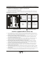

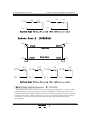

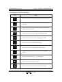
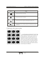
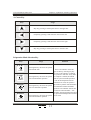
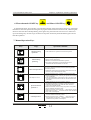
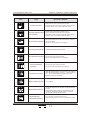
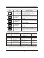


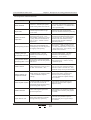
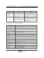
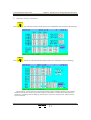
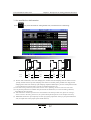
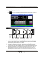
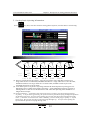

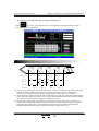

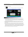

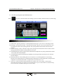
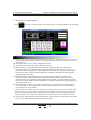
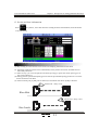

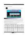
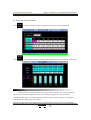
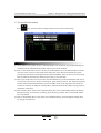

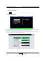
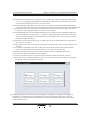
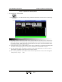

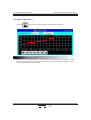
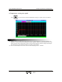

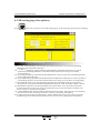
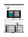

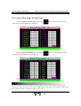
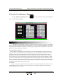


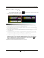
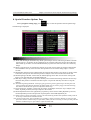
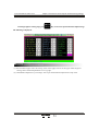


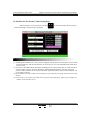

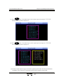
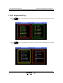
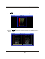

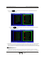


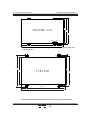
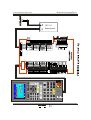
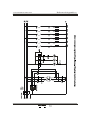


![[édito] - Act Up](http://vs1.manualzilla.com/store/data/006399532_1-4c62fe1ab4a7a5c517a13f6c49266338-150x150.png)