1
User's Manual for BK208S V2.0
Preface
Welcome to use Our Injection Molding Machine Control System
Safety Cautions
(Please read it before installation)
1.In order to ensure the secure operation of the whole system in
case of the abnormal external power and the control system's
failing to function, please set up the external safe circuit for the
I. Danger control system.
2.Upon its failure to detect the abnormal conditions of input and
output, the control system cannot control the output. Therefore,
please design the external circuit and frameworkto ensure the
safe operation of the system.
Cautions
1.Please read this User's Guidance carefully before installation.
2.Do not dismantle the host computer shell and keyboard
without permission.
3. In case of any questions, please dial the after-service service
hotline of PORCHESON.
R
1
User's Manual for BK208S V2.0
Contents
PORCHESON TECHNOLOGY CO.,LTD
B K 2 08 S
Operator's Manual
System Configuration &
Installation
5
Button Operation
specification
8
Explanation of the Param
eter/Function Setting
15
Explanation of the System
Debugging and Setting
34
Input/output State
Detection
46
Reference & Appendices
50
Software Version: V2.0
2 0 08 . 0 4 Version
All copyrights are reserved, any duplication without the prior authorization shall be
forbidden.
R
2
User's Manual for BK208S V2.0
Contents
Contents
Chapter 1: System Configuration&Installation
1、System Configuration&Remark--------------------------------------------page 5
2、Characteristics of PS800CM Control System-----------------------------page 5
3、Installation and Debugging of Computer Control System----------------page 6
Chapter 2:Explanation of the Key Operations
1、Figure of Keyboard on the Operation Panel (See the figure below)----- page 8
2、Explanation of the Parameter Setting-------------------------------------- page 9
3、Explanation of the Parameter setting-------------------------------------- page 10
4、Cursor Key-------------------------------------------------------------------page 10
5、Operation Mode Selection Key---------------------------------------------page 11
6、Electrothermal ON/OFF key and Motor ON/OFF key--------------------page 11
7、Emergen Reset Key----------------------------------------------------------page 11
8、Manual Operation keyboard------------------------------------------------page 12
9、Setting scope of Numeric Items------------------------------------------- page 14
Chapter3:Descriptions on setting parameters/functions
1、The common-hompage while turning on---------------------------------- page 15
2、The C-machinery's homepage while turning on---------------------------page 16
3、Set mould Opening and Close information--------------------------------page 20
4、Set plastic injecting/pressure retaining information--------------------- page 21
5、Set memory information----------------------------------------------------page 22
6、Set the stuff auto-clearing up information---------------------------------page 23
7、Set nozzle thimble information---------------------------------------------page 24
8、Set Slide mold/thimble align information---------------------------------page 25
9、Set loose core information--------------------------------------------------page 26
10、Set the air blow information-----------------------------------------------page 27
11 、Set time/count information------------------------------------------------page 28
12、Set temperature information----------------------------------------------page 29
13、Set warm-up information--------------------------------------------------page 30
14、Set mould information-----------------------------------------------------page 31
15、Set production information----------------------------------------------- page 32
16、Adjust/Set special parameters--------------------------------------------page 33
R
3
User's Manual for BK208S V2.0
Contents
Chapter 4:Instruction for the System Commissioning Settings
1、Engineer setting page--------------------------------------------------------page 34
2、Delay Setting Page-----------------------------------------------------------page 35
3、Pressure/ Flow Slope Setting page----------------------------------------- page 36
4、Pressure Pre-Adjustment page----------------------------------------------page 37
5、Flow Pre-Adjustment page --------------------------------------------------page 38
6、Back Pressure Pre-Adjustment page----------------------------------------page 39
7、Electronic Ruler setting page------------------------------------------------page 40
8、Special Function Option page-----------------------------------------------page 41
9、Standby Function setting page----------------------------------------------page 42
10、Program mable standby Function page------------------------------------page 43
11、Temperature Parameter/Time setting page------------------------------- page 44
12、Machine No./Ex-Factory Value Settiong Page---------------------------page 45
Chapter 5:Input/Output Mode Inspection
1、Input Inspection page--------------------------------------------------------page 46
2、Output Inspection page------------------------------------------------------page 48
Chapter 6:Reference&Appendices
1、BK208S keyboard installation dimension drawing------------------------page 51
2、Exterior dimensions and installation hole position drawing for
switching power supply case -------------------------------------------------------------------Page 51
3、Exterior dimensions and installation hole position drawings for
mainframe------------------------------------------------------------------- page 51
4、PS630BM system wiring drawing------------------------------------------ page 52
5、Relay impel Input and output wiring drawing----------------------------- page 53
6、SSR impel Input and output wiring drawing---------------------------page 54
7、Motor heating wiring drawing---------------------------------------------- page 55
8、Usual methods of interference suppression--------------------------------page 56
R
4
Chapter 1 System Configuration & Installation
User's Manual for BK208S V2.0
Chapter 1 System Configuration & Installation
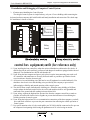
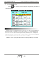
1. System Configuration & Remarks
Q'ty
Remarks
Host Computer
1 Set
26/ 28 + 10
BK2 08 B
Keyboard
1 Set
320 *2 4 0
3
PW6 00
Power pack
1 Set
600 W
4
DB- 15 F
D B- 15F
No.
Code
1
PS8 00 C M
2
Content
1
1m-5m, optional
2. Characteristics of PS800CM Control System
The whole computer may control all functions and temperatures.
The system has bright LCD display and 320*240 Dot 5.7'' concolorous/colorful (optional)
The system adopts CPU design with fast operating speed, precise control and high stability.
The control host computer adopts the blocking design with time-saving installation and rapid
maintenance.
It has the real time function to display time and date in real time.
OFF It has the screen screensaver function, it will power off when there is no operation within 5
minutes.
With 80 groups of mode data storage, it may enter the model description and real-time operating
help in Chinese and English.
The cipher setting and data locking can prevent the operators from changing the established data
arbitrarily to influence the quality of products.
There are multiple languages for your choice that display dynamically in real time.
Packing modulus setting function for 6-digit output may set the packing modulus.
Various self-plugging and tein type programs are applicable for the self-plugging and tein control
in different types.
PID (Proportional Integral Derivative) with self temperature control has 6 sections of temperatures.
Ejector nozzle temperature can be controlled with open or enclosed loop.
Temperature may be preset a week in advance to enable more convenient operation.
Various types of travel control modes, range travel switch/3-path coder/electric ruler (optional)
Various types of Glue Shot ways, 4 sections of Glue Shot and class-3 pressure preservation
Failure Self-detection functions, alarm display and voice prompt
LED indicators for output and input may it convenient to inspect and maintain the system.
Input and output are done by the optically coupled circuit to isolate the interference of the
external circuitry.
In the inspection window, you can inspect all input and output points and the moving states of key.
3-path standard D/A proportional output, the maximum current output 3A (PS610 is 2-path).
Presetting of the voltage and runoff values, proportional valve available for the products in all
brands and better linear proportion.
With remote communication functions, it can let you do the programming and upgrading
softwares easily and remotely.
The management of 255 vertical machine production is by a host networking computer ,
It can accurate statistics each machine production state and produce data type ,so ,it is
convenient to manage.
R
5
Chapter 1 System Configuration & Installation
User's Manual for BK208S V2.0
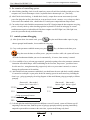
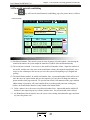
3. Installation and Debugging of Computer Control System
3. 1Cautions upon Installing the Control System
The design of control system is simple and easy, only one 15-core shielding cable connecting the
keyboard and host computer shell with flexible and handy installation and connection. The sketch map
for installation is shown as follows:
S PS 300
X00
X01
X02
X03
X04
X05
X06
X07
POWER
Control
system.
POWER
Strong
eletricity
Equipment
X10
X11
X12
X13
X14
X15
X16
X17
X20
X21
X22
X23
X24
X25
X26
X27
X30
X31
St ro n g
Relay
board
e l et r i c ity
E qu i p m e n t
Strong
eletricity
Equipment
PS 63 0 CM
Ebb e le tr i cit y se ct i on
S tr on g e l e t ri ci t y se c t i on
control box equipment;outfit (for reference only)
( 1) Upon installing the host control box, adopt the enclosed distribution cabinet at the first choice. It
shall be fixed in the well-ventilized, greaseproof and dustproof conditions equipped with a fan and
dustproof. The distribution box shall be stored under 60?.
( 2) Upon fixing the host computer and power pack, please keep the interconnecting parts such as all
AC connectors and transformers as far away from each other as possible to prevent the electric
wave interference from the electronic grid.
( 3) All electric wires and shielding wires shall not be cut off, lengthened or curtailed arbitrarily. You
should use the electric wires and shielding wires provided by this company to prevent from
influencing the reliability and normal operation of the control system.
( 4) The shell of flame couple shall adopt the shielding wire. When the outer shielding of all flame
couples adopts the thermal couple reticles, the reticle and machines shall be well grounded and
connected to the ground with the earthing resistance below 10Ω.
( 5) Upon wiring, separate the high and low pressure line from the computer control line as much as
possible, do not bind all electrical wires together to prevent the interference from affecting the
reliable operation of control system.
( 6) Upon fixing the keyboard and 15-core communication connections of the host computer, you shall
press and tweak with force to prevent the poor connection from affecting the reliable operation of
control system.
( 7) Pay special attention to the oil valve outlet public port YCOM, it shall be connected well to prevent
the computer from inputting while having the phenomenon of oil valve having no motion.
R
6
Chapter 1 System Configuration & Installation
User's Manual for BK208S V2.0
3.2 the examine of controlling system
(1) After finishing installing, check in an all-round way, ensure all such lines including switch power, host
computer case, electric heat output circuit , keyboard electric thermocouple ,etc. join firmly .
(2) After Finish circuit checking , it should check electify , output direct current source namely switch
power line plug take out first, then check to set up an electric circuit , measure every voltage see that it
is the same as the standard value , should observe if switch power output indicator lamp normal.
(3) Cut out the electric after finish the measurement, insert DC8 location input the host computer case plug ,
process electrify check-up .when checking again.the keyboard LCD show in main page in normal
condition,turn on park switch and check if the host computer case RUN light is on, if the light is on,
prove the system has already worked normally.
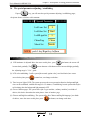
3.3 control systems debugging
(1) After System show the normal work , press
Key,the model button under supervise page,
choosea groupof mould number , then establish in every page.
(2) Carry on the parameter establish memory test, press
Key , the button on the data, press
Key, then store the data, cut off the power , put power on after a while , the system will access
the model numbermaterialsthat you store in automatically , if correct, show memory is normal.
(3) Go on establish of every relevant page materials, (particular oprating refer to the parameter enactment
instruction of the third charper .while establishing for the first time, the pressure , speed have better
be a bit more low , strengthen normally progressively after every movement is normal, so as not to
damage the performance of the machine.
(4) After finished relevant parameters established, you should enter the store and check carefully whether
it is normal to each input / export point, checks the warning system in an all-round way, including the
electric eye , going up promptly; the wiring diagram of shut model button going up promptly as follows
promptly.
Shut model Shut model
button righ 1 button right 2
Shut model Shut model
button left 1 butto left 2
X CO M
X CO M
X 10
X 11
X CO M
Going up promptly button.
X 00
(5) Left and right shut model button push time difference exceed 2 second , system will alarm, stop all
outputting at the same time; Push the system of going up promptly and stop exporting immediately,
output the open model movements at the same time , operate model chang to by hand .
R
7
Chapter 2 Explanation of the Key Operations
User's Manual for BK208S V2.0
Chapter 2 Explanation of the Key Operations
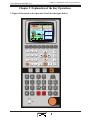
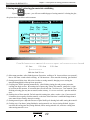
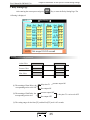
1. Figure of Keyboard on the Operation Panel (See the figure below)
2001.08.18
*Manual*
20:38:08
MID N O: 8 0
228 218 208 198 200 G-618汽车杯外壳
Yild :999999 Md
PRES: 0 Bar
NOW:168899 Md
FLUX: 0 %
SET: 0.0 s
OPRT: 0.0 s
CYCL:25.5 s
EJEC 1SEG 2SEG 3SEG 4SEG
28 C
! Machine run well
MdCs:
350.0 mm
SlMd:
1250.9mm
Scrw:
250.2 mm
R EADY
R
8
Chapter 2 Explanation of the Key Operations
User's Manual for BK208S V2.0
2. Explanation of the Functional Keys
Keys
Usage
Enter into the screen to set the mold opening & locking movement
Enter into the screen to set the Glue Shot and pressure-preserving
movement
Enter into the screen to set the feeding, glue taking and automatic
material removal movement
Enter the page of seat platform, thimble, page slippery model,
and releasing core and releasing gas.
Enter the page of setting up temperature, preheating
Enter the page of setting up time, counting
Enter setting up and modification page of mould and production material
Return to monitor pages at any moment
Entering online-help pages at present
R
9
Chapter 2 Explanation of the Key Operations
User's Manual for BK208S V2.0
3. Instruction of Parameter setting mode
The numerical key from0 to 9 in data setting page is
used for data importing, when the electronic lock is in
" OFF " state, this ten numerical keys are locked, guarantee
the materials not to be altered at will . There are 26 English
letters and special symbols separately on 0 to 9 numerical
keys for the mould name inputting in Chinese or English,
the inputting machine serial number. [Remove key] you can
press this key to remove the wrong when the parameter or
the serial number name have been wrongly written[Input]
key serve as function selection key if there are functions to
be select and as confirm key if there are items to confirm.
4. Vernier key
Keys
Usage
Jump rank key, cursor goes the previous line after pressing this key
Change arrange key, cursor goes the left arranging after pressing this key
Change arrange key, cursor goes the right arranging after pressing this key
Jump rank key, cursor goes the previous line after pressing this key
R
10
Chapter 2 Explanation of the Key Operations
User's Manual for BK208S V2.0
5.the options button of operating mode
Keys
Usage
Remarks
There is an indicator at the upper
left corner of every key,after pressing
state after press the button.
one of these key,this indicator is on,
that showthe system is in the just state.
The default mode is manual operation.
S Press this key and system enters the If temperature hasnot reached the
establishing value , the system is
semi-automatically operation
unable to operate semi-automatically,
when pressing buttons as semi-autom
atically, the indicator lamp is not on.
Press this key and s system to enter the Untiltemperature reaches the establ
full-automatically operation
ishing value, the set can run
semi-automatically .
System enter the manual operation
6. Electrothermal ON/OFF key
and Motor ON/OFF key
In the manual mode, press a button the indicator in the left up is on which indicates this function has
already been on; the indicator lamp left above is off when press the button once again ,shows this function
state has already been closed , continue press the key, this function will be opened or closed in turn. When
the emergency switch stops, the motor cuts out rapidly, but does not influence the electric heat work.
R
11
Chapter 2 Explanation of the Key Operations
User's Manual for BK208S V2.0
8. Manual operation key
Keys
Operation Conditions
Usage
Open mould operate
1 . turning on mould don't reach stop position;
1. press keeping time has not ended;
jet operate ion
2. the temperature of the material tube must reach
to the establishing value range;
Jet back operation
Tip out operation
Retreating operation
1. the temperature of material tube already reached
the establishing value range;
1. if using the journey, the journey has not reached the positi
on of stopping;
2. If using time, the time of appearing and has not ended;
3. the opened-mould already got the position of stopping;
4. if using releasing core /entangling, produce /already;
Core retreat tooth finish
5. if using slippery mould, Left or right slippery mould has
already got to make a reservation;
1. if using the journey, the journey has not reached
the position of stopping ;
2. if using time, the time of retreating has not ended ;
The operation of seat
move forward
The operation of seat
move back
The operating of
1 . unconditional;
1 . unconditional;
1. the speed of t adjusting he mould to slow down
after pressing this key bright;
adjusting mould
The blowing operation
1. chooses for blowing;
2. Blow time has not ended;
R
12
Chapter 2 Explanation of the Key Operations
User's Manual for BK208S V2.0
Keys
Usage
The operation of
adding material
Operation Conditions
1 . not reach end position for adding raw material
2.The temperature of the material tube must reach
in the establishing value range;
1. chooses for clearing material;
The automatic operation 2. The times of clearing material has not ended;
3. the temperature of the material tube must reach in
for clearing material
the establishing value range;
1. stop opening mould
Left slipping operation
2.stop retreating;
3. left slipping model has not got the end location
1. stop opening mould
Right Slipping operation 2. stop retreating;
3. right slipping model has not got the end location
The pressure adjusting
1 .after pressing this bright key, you can enter the
operation in advance
Back orientation/ pressure
increasing
Back orientation/ pressure
minishing
pressure adjusting operation
1. not choose the pressure-reservation ; realize the
advance orientation operation
2. already choose the pressure-reservation; Realize
the increasing-pressure operation
1.not choose the pressure-reservation ; realize the
advance orientation operation
2. already choose the pressure-reservation; Realize
the monishing-pressure operation
1.choose to use
wringing tooth operation 2.advance-time not end
3.stop retreating
Retreat wringing tooth
operation
1. Choose to use
2. advance-time not end
3. Stop retreating
R
13
Chapter 2 Explanation of the Key Operations
User's Manual for BK208S V2.0
Keys
Usage
Operation Conditions
Enter core operation
1. choose to .releases the core
2. the entering- core not to ending position or;
Time has not finished
3. stop retreating
Output core operation
1. choose to .take out the core
2. the outputting- core not to ending position or;
Time has not finished
3.stop retreating
紧急停止
9. Setting Scope of Numeric Items
Number
Setting Items
Setting Scope
1
Establishing the pressure
2
Establish the speed
3
Establish temperature
4
The mould materials storing
5
Establish jet out position
Digital≤999.9
6
If the establishing value beyond
thescope of the above,
Digital≤999.9
mm
mm
7
Storage of mold data
Digital≤5999.9
mm
8
Book the output
9
Establish Lock mould position
Digital≤999.9
Unit
Second
Digital≤140
B ar
Digital≤99
%
Digital≤999 Max700C
for actual use Centigarade
℃
Digital≤80
Digital≤999999
Number
PC
In case of the set values exceed the above-mentioned scopes, the system will not accept the numbers
set and keep the original set values. For the habit of data input, the data input of this system is display
from right to left.
R
14
Chapter 3: Descriptions on setting parameters/functions
User's Manual for BK208S V2.0
Chapter three: parameter / function enactment explaining.
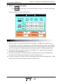
1.the machine-start main page of ordinary machine,
urn on the power ,turn round red urgent switch , computer operate light RUN light on ,you can
see the following pictures on the screen, the control system has already worked normally at this moment,
you can begin to operate the machine . The ready machine runs normally.
2001.08.01
*Manual*
20:31:05
Ejec Seg1 Seg2 Seg3 Seg4 OilT
228 218 208 198 200 28
MdNo:78Name:PS620BK108
Yild:999999 Md Pres: 0 Bar
Now:1688899 Md Flux: 0
%
Sets: 0.0 s
Oper: 0.0 s
Cycl: 25.5 s
MdCs:350.0 mm
SlMd: 1250.5mm
Scrw: 250.0 mm
Ready
Machine Run Well
You can enter the picture of the machine
when push any time after starting the machine
again. This page offer temperature monitor and machine movement monitor. Mould nameand mould
number is establishing by the materials picture of the mould. Temperature arranges and present oil
temperature shows actual value of every sections. You can't alter the materials. Every functionof the
picture stated as follows:
The descriptions on mode:
Meanings
Mode
Show the motor has already operated;
Show the electric heat has already been opened;
Show lubricate-pump that is pump oil;
Show the electric eye is imported normally;
R
15
Chapter 3: Descriptions on setting parameters/functions
User's Manual for BK208S V2.0
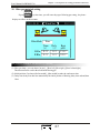
2.C Type machine machine-start main page
urn on the power ,turn round red urgent switch , computer operate light RUN light on ,you can
see the following pictures on the screen, the control system has already worked normally at this moment,
you can begin to operate the machine . The ready machine runs normally.
20:38:08
*Manual*
EJEC 1SEG 2SEG 3SEG 4SEG MID NO: 80
228 218 208 198 200 G-618汽车杯外壳
Yild:999999 Md
PRES: 0 Bar
NOW:168899 Md
FLUX: 0 %
SET: 0.0 s
OPRT: 0.0 s
CYCL:25.5 s
2001.08.18
28 C
! Machine run well
You can enter the picture of the machine
MdCs:
350.0 mm
SlMd:
1250.9mm
Scrw:250.2 mm
READY
page when push any time after starting the machine
again. This page offer temperature monitor and machine movement monitor. Mould nameand mould number is
establishing by the materials picture of the mould. Temperature arranges and present oil temperature shows
actual value of every sections. You can't alter the materials. Every functionof the picture stated as follows:
The descriptions on mode:
Meanings
Mode
Show the motor has already operated;
Show the electric heat has already been opened;
Show lubricate-pump that is pump oil;
Show the electric eye is imported normally;
R
16
Chapter 3: Descriptions on setting parameters/functions
User's Manual for BK208S V2.0
The descriptions on display:
Display
Meanings and descriptions
Manual
The running mode of the machine;
Second
sections it express this section is being heated;
Mould
number it express the using-model Serial number at present;
Produce
in advance; it expresses setting value of the times mould-opening at present
Remember g the mould-making times of the mould at present in the course
of operating automatically;
process the system operates cycle-time actually;
At present
Whole
when carrying have established time value, data will increase to it, then carry
Operation
on next movement, if number established is times number. Shows will go on
until reaching value of times number.
Settlement
Pressure
the time value or counter value of operating:
pressure-established evalue of operating
Flo the flow-
established value of operating
Lock mould
show locking mould position at present, the unit is mm. ;
Slippery mould
Spiral shell's pole
The machine runs
normally
Ready
Re-press
shows slippery model's position at present, the unit is mm. ;
shows the present spiral shell's pole position, the unit is mm. ;
Show the warning content now
Show the movements of the machine operates now
key to show the following menus
2003.01.06
Date
01日
01日
01日
01日
01日
01日
01日
01日
01日
01日
Alarm note
10:07:12
Happen Alarm content Unchain
10:03 Abnormal sensors
10:03
Clamping
mould
not
completed
on
time
12:08
12:08
Plastic
melting
not
completed
on
time
15:16
15:16
Failure
of
mould
releasing
15:17
15:17
Mould
opening
not
fixed
on
time
15:18
15:18
15:19 Mould opening not fixed
15:19
15:20 Failure of manipulator
15:20
15:21 Failure of motor
15:21
15:22 End of the cysle time
15:22
15:23 Scheduled moukd opening
15:23
R
17
Chapter 3: Descriptions on setting parameters/functions
User's Manual for BK208S V2.0
Descriptions on alarm mode
Alarm
Source
Solution
ThisX04 terms message show When Check whether the electricity is
electric eye Input have no signal; correct and electric eye is hidden
But
the alarm is being only made
is unusual
or lost efficiency long.
only when shutting the mould .
check whether unusual in shutting
Shut the mould has not Fail to finish shutting mould movem mould course, if normal you should
ents in 搒 hut the mould to prescribe transfer longer the" shut mould
finished regularly
a time limit ".
prescribes a time limit ".
The electric eye
Check whether mould have incidental,
Protect-mould time in If low-voltage time arrives, warning
you can transfer longer 搇 ow-voltage
low-voltagly arrive,
not transferred high-voltage yet.
time "if possible.
Warning when X00 has no signal Please check whether the safety lock
the safely Input trouble input in the course of shutting the is put through normally
mould:
and input end X00.is correct connection.
The button trouble of
Shutting mould (one
As only one X10 and X11 warning
pair of slippery moulds
have not this warning )
Please check whether left and right
shutting mould button connect correctly
to the input end and press normally side
to side.
Check Whether process is unusual
and the material in the storage bucket
has been used up , if usual, you can
proper to transfer longer " store
material prescribe a time limit ".
Storing the material
has not finished
regularly
At storing material, in “store
material prescribe a time limit
in time ". Fail to finish storing
material movements:
Open mould has not
finished regularly
Fail to open mould to put in place Check mould-open , if no unusual,
in “open the mould to prescribe a
you can proper to transfer longer "
time limit ".
Trouble of the motor
Warning when the motor-protect
point has signals input
Cycle has already
Automatic production cycle goes
ended
beyond setting for [cycle ].
Check whether oil pressure motor
causes the hot relay to produce
movements of protecting because the
overload work..
Check automatic process, if have no
unusual, can proper to transfer [cycle
time] established longer
Solution: If make machine run
continually after got output, you can
put the {Shut down after warning}in
management page {No}: Or make the
total amount of present no number
mould-opening as zero.
Opening mould has not When manual tip our , opening
Operate lock movements of the mould
got to reservation
mould have not got to the stopping again, or check whether the stopping
position
position
X12 of opening mould put through.
Launch output park and modulusThe output has already opening time has reach output value
established in advance, the machine
got schedule
stops turning round.
R
18
Chapter 3: Descriptions on setting parameters/functions
User's Manual for BK208S V2.0
Operation/clewing state explaining
Alarm
The First sections
temperature is high
The Second sections
temperature is high
The Third sections
temperature is high
The first section
temperature is low
The Second sections
temperature is low
The Third sections
temperature is low
The first section breaks
The Second section breaks
Source
The machine material actual temperature tube is higher than the
establishing value of upper limit .
The machine material actual temperature tube is lower than the
establishing value of upper limit .
Machine material tube corresponding temperature sensing line
break or temperature sensing line have trouble.
The Third section breaks
Retreating not reach
the position
The slippery mould has not
got to the reservation.
The automatic clear material
is finished
The function has not been
selected
Please turn on motor,
Withdraw from and pressshowing state first
Enters pressing showingthe state firstly
when operating the slippery-mould or shutting-mould , Retreating
not reach the position.
When operating the thimble or shutting-mould, the slippery-mould
has not got to the reservation .
when using the automatic clear material , according to the number
of times.established movements.
When press a certain function key , but this function has not been
for use .
if choose to use motor ,registering motor is not start when press
half / full-automatic key
When choose the pressure adjustment, operation is not increase ,
reduce buttons .
No pressure adjustment choose, whenpress the key of operation
increasing or reducing
R
19
Chapter 3: Descriptions on setting parameters/functions
User's Manual for BK208S V2.0
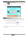
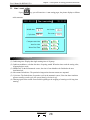
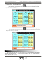
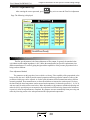
3.unlock mould materials enactment
Press
key,will enter turn on / shut mould establishing page , picture shows as follows
at this moment.
2003.01.06
Open/CloseMld
PRES FLUX PLAC
(bar) (%) (mm)
CLOF 55
32
20.0
LOWP 15
20
5.0
2.5s
28
HIGP 120
O.SL
O.FS
UNLD
50
55
35
50.0
220.0
350.0
20
50
30
10:07:12
MVMDPLAC
350.0 mm
UNLDTIME
2.2
MCHAND
Use
LOWPLIM 6.0 (s) OPNCLSLIM 50.0 (s)
The parameter established / movement procedure / the function way explaining
shut fast─ ── ─ →Low-voltage─ ─ ── →High pressure─ ─ ── →Finish locking
High-pressure time
20 .0m m
5. 0m m
(X03)
├─ ─ ── ── →
Low-voltagly Protection time 6. 0sec
(1) Lock the mould : enter the locking mould fast, walk to 20. 0mm , enter low-voltage locking mould ,
walk to 5 .0mm more . Enter high pressure locking mould , wait high-pressure time get to end or X03
input point is ON , then locking moulds have finished . warning [Low-voltagly Protection time have
arrived] when low-voltage time arrive but does not transfer to high pressure yet, and opened the mould
automatically.
(2) low-voltagly ime limit : low-voltagly Protection time of shutting mould, please don't establish too
big as much as possible , it should be suitable , otherwise the situation of protecting the mould will
not appear.
slow opening ─ ─ ──→ fast Opening ──── → low opening ── ──→Finish opening
50. 0m m
22 0 . 0 mm
35 0. 0 mm
(3) Open mould ;carry throughopen mould unload firstly, the time enter the mould-opening slow speed ,
when walking to 50.0mm ,Switch to turn on mould fast ,when walking to 220 .0mm., Switch to
turning on mould's low-speed , when walking to 350.0mm more ,switch is over. at the.
(4) Open and shut the mould limit time: Show the restriction time to turning on the mould or locking the
mould, please don't establish too small as much as possible , should suitable ,
otherwise systemwill warning [turn on / shut mould not finished timing ].
(5) Manipulator: If need to use the manipulator , please choose [use ], after choosing to use, at the
full-automatic mode, output manipulator signal after machine turn on mould, lock mould enter the
next circulation after ensure received mechanical signa and expire manipulator signal export at the
same time .
R
20
Chapter 3: Descriptions on setting parameters/functions
User's Manual for BK208S V2.0
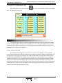
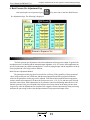
4.glue-jetting / pressure-keeping enacement
If press
key , you will enter the page ofglue-jetting / pressure-keeping enacemen , the picture
shows as follows at this moment:
2003.01.06
Inje/KeePres
Pres
(bar)
Inj1一55
Inj2二22
Inj3三 60
KpPr 18
Flux Plac
(%) (mm)
75 120.0
20
70.0
59
5.0
19
10:07:12
ScrwPlac
350.9 mm
KpPrTime
2.0
InjTTime 12.0 (s)
PmtError
+
- 3.5 (mm)
InjCheck Nuse
InjCKpts
5.1 (mm)
The parameter established / movement procedure / the function way explaining
1se g─ ── →2s eg── ─ →3 se g─ ── →pP r es
12 0 . 0 mm
70 .0 m m
5 . 0m m
├─ ──── ─── ─ ── ── ─ ──→
T im e 1 2 . 0 se c
(1) the first section jetting reach to 120. 0mm ,then switch to seconf section . walk to 70 0mm more
switch to the third sections, movement procedure: Walk to 5 0mm more . switch to pressure-keeping.
(2) Supervise the normal jetting journey .begin to time promptly while enteringthe jetting , wait for time
end , : Whether the distance arrives switch to pressure pretection promptly, so the time of jetting should
be greater than real time.
(3) jetting measure : Can choose [use ]and [no use], when choosing to use under half / full-automatic
mode, The computer fetches shooting the average number value of terminal point of 20 the first moulds
as jetting our check-point automatically, users can establish the allowing error number value range . If
after the 21st mould , find that shoots not reaching this check point or exceeding this check point , then
warning [jetting fail ], management regard this mould as the bad product in output at the same time .
R
21
Chapter 3: Descriptions on setting parameters/functions
User's Manual for BK208S V2.0
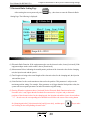
5.Storing material / releasing glue materials establishing
If press
key once , you will enter establish pages of storing material / releasing the glue ,
the picture shows as follows at this moment:
2003.01.06
StoreRaw/Deco/Stuf
10:07:12
Pres Flux Place
(bar) (%) (mm)
BDcp 30
SMat 75
15
220.0
55
150.0
20
25
20.0
Fdcp
CoolTime 8.5 (s)
ScrwPlac
250.0 mm
Acoltime
0.5
SMatLttm 180.0(s)
SMatBPre 15(bar)
The parameter established / movement procedure / the function way explaining
Fr on R e l e as e─ ─ ─ →ma te r ia l─ ─ ── →po s t re le a s e─ ── →r el sa se d
20 .0 m m
150 . 0 mm
2 20 . 0mm
├── ── ─→
Melt time limit 25.0 sec
(1) Movement procedure: after finished pressure-Protection , walking to 20. 0 mm switch to store material ,
then to 150 0mm. switch to back releasing . to 220.0mm.more . Store material releaseing glue finished
(2) Storing material delay time: delay time in order to storing material, changing over to storing the
material through delayed after pressure pretection.
(3) Coolling time: While operating automatically , after finishing jetting glue and pressure pretection ,
coolling time begin to time . the running time of protect,ing storing the material , pump also is a part
of cool time at this moment , if movement time exceed cool time , cool time over , store material , after
finishing releasing glue may turn on mould, on the contrary , it is over to cool time , open the mould at
once.
(4) limiting time of Store material: For lack material warning time ,when reach to time ,if store material
is immature .then regard as lack the material, so the time of the limit time is established longer than to
store material time actually, otherwise warning .
(5) Storing material press: adjust the Pressure of spiral shell's pole drawing back while storing the material .
(6) Cooling way: Can choose jetting-finished or storing material over, choose jetting-finished , begin to
start time the cooling time after jetting-finished, choose storing material over, start time cooling time
when storing material is over.
R
22
Chapter 3: Descriptions on setting parameters/functions
User's Manual for BK208S V2.0
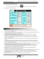
6、 The automatic clear material establishing
When press
key two times , you will enter automatic clear material establishing pages,
the picture shows as follows at this moment:
Auto Clear Ma
2003.01.06
10:07:12
Pres Flux Time
(bar) (%) (s)
InjB
30
25
2.5
Purg
85
65
12.0
Inje
65
50
6.5
ScrwPlac
350.9 mm
PurgeTms
20
AutoPurg
Nuse
The parameter established / movement procedure / the function way explaining
(1) Automatic clear material method:The automatic clear material function is had [uses ] in the manual
mode, press the automatic clear material key, the system begins to carry out automatic clearing
material movements, the movement procedure is as follows:
seat up
jet out
clear material
pump latter
[no ]
whether number of times
already arrive
[Yes]
Over
(2) The number of times of clear material : repeated to make clear material , the times of movements
that jet movement.
R
23
Chapter 3: Descriptions on setting parameters/functions
User's Manual for BK208S V2.0
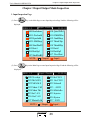
7.The seat platform / the thimble materials setting
If press
key, you will enter a platform / the thimble and set pages, the picture
displays as follows at this moment:
2001.08.01
NOZZ/EJEC SET
20:31:05
PRES FLUX TIME
(Bar) (%) (S)
NZUP
NDWN
60
20
35
15
1.9
1.5
KEEP
ETOP
EBTM
30
70
50
25
25
19
0.8
2.5
2.0
E.ADVDLY
0.3 (s)
AUTO.EUP
Nuse
EJETMode
CTms
EJETMES
0.2
E.RETDLY 0.2 (s)
The parameter established / movement procedure / the function way explaining
(1) The seat rises automatically: Can choose [no use] or [finish storing] or [cooling over ]; if
choose [finish storing] after storing material ,make rising movement when operating automati
cally; if choose [cooling over ], after finishing, make a rising movement when operating
automatically.
(2) Thimble way: Can choose [order] or [stay]; if choose [stay ], then on semi-automatic state,
enter movement reach terminal then stop to carry, make and carry retreating until the next
circulation before imprison mould.
(3) The times of the thimble: Set the times of thimble movement
(4) Enter delay: While operating automatically, delay time after finishing opening the mould and
then carry enter.
(5) return delay : While operating automatically , delay time after finishing carrying into enter
and then carry and retreat again.
(6) [The note ]: while manually , it is not limited by the times (but can't be 0000 ) .
R
24
User's Manual for BK208S V2.0
Chapter 3: Descriptions on setting parameters/functions
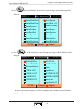
8..slippery Mould /orienting material setting
If press
key tow times, you will enter the page of slippery mould / orienting setting, the picture
displays as follows at this moment:
2003.01.06
SdMd set
SdMdPlac
Pres Flux
(bar)
(%)
1250.9 mm
50
SdotFast
45
25
SdotSlow
25
50
SdInFast
45
20
SdInSlow
25
140
LockUp
99
140
LockDn
99
SdMdFunc Nuse
LSldDely 0.3 (s)
10:07:12
Plac
(mm)
599.9
1250.0
500.0
0.0
1250.0
1250.0
SdMdMode SSlI
RSldDely 0.3 (s)
The parameter established / movement procedure / the function way explaining
(1) Slippery model function: Can press the input key to choose [Not Use ] or [Use ], when choose [Use ]
. the set way of slippery model is effectively.
(2) Slippery model way: Can press the input key to choose [slip on the left ], [Slip in right ] or [Pair slips ].
(3) Choose slip on the left: Open mould ---Do left slippery movements ---- Slip on the left ----Thimble
----- Thimble finished ---- Wait ----- Press the left / right shut mould button -----Slip in right ----- finish
Slipping in right -----Shut the mould ----- Begin the second circulation.
(4) Choose slip in right : Open mould ---- Do slippery movements in right ---- Slip in right ----Thimble
---- Thimble finished--- Wait --- Press the left / rignt shut the mould button --- Slip on the left -----finish
Slipping on the left ----Shut the mould ----- Begin the second circulation
(5) Choose pair slip: Open mould ---Wait ---Press the left / right shut the mould button, if the model does
slippery movements in right as above -----Then slippery movements on the left -----finish Slipping on
the left ------Shut the mould -------Begin the second circulation.
(6) Single slide machine : slip out if Slip on the left, slip into if slip in right.
(7) The delay slipping on the left: the time from open the mould to the time of beginning slipping left.
(8) The delay slipping on the right: the time from open the mould to the time of beginning slipping right
R
25
Chapter 3: Descriptions on setting parameters/functions
User's Manual for BK208S V2.0
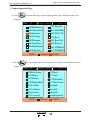
9、Release core materials setting
if press
key three times, you will enter the page of release core/ entangle tooth setting ,
the picture displays as follows at this moment:
Tak Core
2003.01.06
10:07:12
Mold Plac Pres Flux Time Plac
(mm)
250.9 mm (bar) (%) Toth
50
220.0
CrIn
30
3.5
120.0
CrOT 50
30
3.5
50
180.0
ThIn
30
350
80.0
50
Thot
30
350
CoreMode
Nuse
ThinDely
1.2
TothFunc
(s) ThotDely
Muse
1.2 (s)
The parameter established / the function way explaining
(1) pump core shape : You can choose [stop time ], [stop journey ], [entangle tooth count ], [no use ],
choose [stop time ], set time to stop pumping core movements; choose [stop journey ], stop pumping
core movements when inputting some breaks alarms [ON ]; if choose [entangle tooth count] , you can
control the entangle tooth , stopping determined by the pulse number of inputting entangle tooth.
(2) Initial position: the begin position of Enter Core and Produce Core , namely where stop template ,
the settlement value that pumping core A , B.
(3) The delay of entering the core : delay first after run automatically enter the core B initial position ,
when delay-time end, then make procedure movements of entering core B.
(4) The delay of output Core B: delay first after run automatically enter the core B initial position ,. When
delay-time end , then make procedure movements of output core B.
R
26
User's Manual for BK208S V2.0
Chapter 3: Descriptions on setting parameters/functions
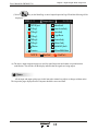
10、Blow gas materials setting
If press
key four times, you will enter the page of blowing gas setting , the picture
displays as follows at this moment:
2001.08.01
BlowMode
Wind Set
20:31:05
Nuse
Dely
(s)
0.2
0.2
Time
(s)
LBlw 0.8
R Blw 0.8
Begi
plac
C.M.F
O.M.F
The parameter established / the function way explaining
(1) Blow gas shape : you can choose [no use ], [ blow left], [blow right ], [blow left and right] .
This function can be used in the mould need blowing gas
(2) Initial position: Can choose [before mould ] ,[after mould] to make the settlement value
(3) Delay time: delay first after run automatically the initial position of blowing, delay time end and then
blow.
R
27
Chapter 3: Descriptions on setting parameters/functions
User's Manual for BK208S V2.0
11、time / count setting
if press
key, you will enter time / count setting pages, the picture displays as follows
at this moment:
2001.08.01
Time / count setting
20:31:05
Middle time
0.5
Act.Li.time
20.0
Cycle time
50.9
Fau .warn
10.5
Computer-start time
Auto.On. time
Motor. Run Time
16989 H
6599 H
8998 H
59
25
29
M
M
M
The parameter setting instruction
(1) Lubricating time: Display that single running time of oil pump.
(2) Lubricate moduluses: calculate the times of opening mould .When the times reach the setting value,
oil pump begin to work.
(3) Middle time: In the full-automatic course, the time is from thimble work finished to the next
circulation lock ,
(4) Movements limited time: The permission longest time that movements are outputted
(5) Cycle time: The limited time of operation cycle in the automatic course, if the time that circulation
operates actually exceeds cycle, the system warn [cycle time is up ].
(6) Warning signal of the trouble: from trouble beginning to the stopping of warning avoid a long time
warning.
R
28
Chapter 3: Descriptions on setting parameters/functions
User's Manual for BK208S V2.0
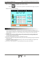
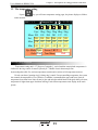
12、The temperature setting
if press
key, you will enter temperature setting pages, the picture displays as follows
at this moment:
Temprat Set
2003.1.2
15:32:15
0
1
2
3
4
5
Ejec
Meas 205
Set 210
Max +10
Min -10
1Seg
199
205
+15
-15
2Seg
200
200
+15
-15
3Seg
201
200
+15
-15
4Seg
197
198
+15
-15
5Seg
135
150
+15
-15
Eje.Mode Open
Galv Close
Screw.C.BT.T
Tem.Warm
10.0
Well
Parameter setting instruction
Temperature setting unit is 1℃ [degrees Centigrade ], vertical machine material tube temperature is
feedback to the ring control of control system by K , J Model electric thermocouple line.
System altogether offer five sections temperature controls and a sections of oil temperature measure.
Dozzle can choose [opening ring] /[closing ring ] control. Except controlling temperature, the system
also controls the temperature of every district, see whether it surmounted the upper and lower limit set,
temperature lower than lower limit can not jet glue and melt glue which hinder cold spiral shell's pole start;
temperature is higher than upper limit then warning .Each section temperature states display in the main
picture .
R
29
Chapter 3: Descriptions on setting parameters/functions
User's Manual for BK208S V2.0
13、Preheat materials setting
if press
key Two times, you will enter the preheat setting pages, the picture displays as
follows at this moment:
2001.08.01
Func Nuse
Week
Mon
Tue
Wed
Thu
Fri
Sat
Sun
Set
ON
ON
ON
ON
ON
ON
ON
WarmUp set
20:31:05
Doday: Sat
Open-Tim
8:30
8:00
7:30
7:00
6:30
8:24
9:00
Set
ON
ON
ON
ON
ON
ON
ON
Clos-Tim
16:40
17:00
17:30
18:00
18:30
19:00
19:30
parameter setting instruction
Preheating Function: make an appointment in seven days of one week. This system offers the function
that whether some day use the heating in advance or not. You will not use preheat function by choosing
[OFF ]. If you chose [ON ], the system will control the heating of the heating system, according to the
setting value of turning on / off time in the day. The machine will heat the material tube to working temp
erature automatically before the operator works, reduce the time of waiting for .
*[The note ]: The time inputting value adopts 24 hours.It is expressing 12:00 at night if input 00:00
R
30
Chapter 3: Descriptions on setting parameters/functions
User's Manual for BK208S V2.0
14.The mould materials establishing
Press
key, will enter the mould materials establishing pages, the picture shows as follows
at this moment:
2001.08.01
Mld Articles
Rend
Mld.No.
03
Mld.Name PS620BK108
Mid View
NO
Mld Name
01
ABS小马车玩具
ABS小马车后轮
02
ABS小马车前轮
03
04
ABS大马车玩具
ABS大马车后轮
05
20:31:05
Save
Ddlete
Chinese
Save time
2003.01.01
2003.01.01
2003.01.01
2003.01.01
2003.01.01
The parameter establishing explaining
(1) Mould serial number: This control system can store 80 groups of mould symbols , after altering the
mould serial number, the system output the materials of symbol of the mould automatically.
(2) The mould stores method : Cursor move to the mould serial number colume , import the numberl of
the mould , and then move the cursor to the mould name column, after input the mould name, move
cursor to store column.press the store key to store. this system offer inputting way in English and
spelling.
.(3) The mould fetches method : in mould serial number fence , input mould number which will be read ,
move the cursor to ourput column and press the import key to read .this will change the number ar
present and the whole page materials . For prevent from in half / full-automatic mode, page establish
sudden change of parameter will cause harmful effects to product quality and cause contingency
acciden , the mould fetches function is only limited to the manual mode.
( 4) Delete method : move the cursor to mould serial number fence , input mould number which will
bedeleted , then import import key to delete in delete fence . the present mould can't be deleted.
( 5) the Method that refer the mould : move the cursor to the scanning fenceand utilize upper and lower
key move the picture refer .
R
31
Chapter 3: Descriptions on setting parameters/functions
User's Manual for BK208S V2.0
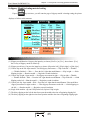
15、The production materials establishing
If press
the buttons twice , you will enter production materials establishing pages, the
picture shows as follows at this moment:
2001.08.01 ProductManager
Set Mode 999999
Mod1 Qua
20
Warm Stop Nuse
Product record
Date Mold
03.01.01 13
03.01.02 03
03.01.03 23
03.01.04 05
03.01.05 01
20:31:05
Bad
Molds Good
900
1780
20
Zero
Tnun
999999
999999
999999
999999
999999
Good
999999
999999
999999
999999
999999
Bad
9999
9999
9999
9999
9999
The parameter establishing explaining
(1) The good product is equal to the moduluses has already been made multiply by the quantity of a
mould and deduct the bad . The bad product is controlled by the function of shotting and measure ,
when jetting measuring is in use, n the course , if excessive or insufficient state taking place , bad
product increase one mould quantity value, and warning [measure to the bad product ].
(2) Establishing moduluses: establishing produce Modulus in advance, system automatic reach the frirst
5 moulds of already opening modulus established, the alarming until the modulus arrives.
(3) Shut down warning : Can choose [use ] , [not need ], after establishing moduluses reaching if
choosing no, machine continued producing, did not shut down until after the operator shuts down.
(4) Method that the production record refer: move the cursor to production record fence and utilize
upper and lower key to look out .
R
32
Chapter 3: Descriptions on setting parameters/functions
User's Manual for BK208S V2.0
16、The special parameter adjusting / establishing
If press
key, you will enter the special parameter adjusting / establishing pages,
the picture shows as follows at this moment:
Special Parameter
2001.08.01
Lcd Lum Set
8
LcdColor Set
Nrml
LcdBLigntSet
5
China/Eng
20:31:05
China
Nmode
Monit Set
NOTE:push L key/Rignt key AdjIum
The parameter establishing explaining
(1) LCD luminance is adjusted: Move the cursor to this place , press
become dark gradually; The
the button, the screen will
screen character of the button will be increased bright gradually,
the adjusting range is " 1-16 " grade.
(2) LCD color establishing : It offer system [the normal, against color ] two kind choice,have cursor
moved to the place,press
button later, can change each other .
(3) Time in a poor light of LCD: The system possesses the screen protection function, background light
time can be established, establish the range for 1-5 minutes, if establishing has not operated the keybo
ard in timing, then the background light automatic OFF.
(4) Choose Monitor pages: The system offers [the C type machine , ordinary machine ] two kinds of
choices, this choice determines the main picture show of monitor- page
(5) Chinese and English establishing : The system offers [the Chinese and English language ] two kinds
of choices, move the cursor to this place ,press
the button, can change each other.
R
33
Chapter 4 Instructions for the System Commissioning Settings
User's Manual for BK208S V2.0
Chapter four: System Debugs Instruction
1.Engineer setting page
Press
Key,button In the main picture, you will enter engineer's setting page, the picture
displays as follows at this moment:
2001.08.01
Pass
Engineerset
****
Pour.Pl No
SW-999999999
Contro.NO.
PS-999999999
Version
PS800AM - v2
20:31:05
SetDelay
SetPres/Flux Slopel
SetPres/Flux/BackPre
E.Ruler
SPecialFunctionSet
BackFunc/PointsSelec
Tempreture/Time Pram
Code/FactValueSet
NOTE Please Input Password
Input the password * * **And then if the password is correct then your can enter
;
if incorrect
, you can enter until the correct password is entered. Then you can enterthe
systematic parameter setting pages after. If you are the end user of the machine, you need not to
adjust the systematic parameter please contact supplier if there is doubt, otherwisethe parameter
is adjusted messily, may damage the performance of the lathe and cause unstableor unable to run.
After the password is input correctly, the cursor will jump to the first column on the right
automatically , can choose every column content again with the
key ,press, the buttonto
enter. Or press buttons the following and enter the corresponding page directly:
press. The
button enters the page.
Key
Entering Page
Key
<Delay Setting>
Entering Page
<Special Function Options>
<Standby Function Setting>
<Programmable Standby
Points>
<Pressure/Flow Setting I>
<Pressure/Flow Setting II>
<Pressure Pre-Adjustment>
<Flow Pre-Adjustment>
<Back Pressure Adjustment>
<Temperature Parameter/
Time Setting>
<Machine No./Ex-Factory
Value Setting>
<Electronic Ruler Setting>
R
34
Chapter 4 Instructions for the System Commissioning Settings
User's Manual for BK208S V2.0
2. Delay Setting Page
After entering the correct password, press
Key to enter the Delay Setting Page. The
following is displayed:
Set Delay
RET<<
Begi
0.0
0.0
0.0
0.0
0.0
0.0
0.0
0.0
Act
M.Cl
ADV
INJE
FEED
DECO
RET
OPEN
ADV
End
0.0
0.0
0.0
0.0
0.0
0.0
0.0
0.0
Begi
0.0
0.0
0.0
0.0
0.0
0.0
0.0
***
Act End
RET 0.0
THIN 0.0
THIC 0.0
A_IN 0.0
AOUT 0.0
B_IN 0.0
BOUT 0.0
DIFF 0.0
NOTE Set scope 0.0-0.5 second
Description on setting parameters
Action Valve
Pressure Valve
Flow Valve
T1
(1) The meaning of Start Delay: the
corresponding action valve ON→
(2) The meaning of End Delay: the
→
corresponding action valve
T2
T1
T2
delay time T1 → pressure output ON
flow output ON
pressure output OFF
→ delay time T2 → action valve OFF
flow output OFF
(3) The setting ranges for the Start [T1] and the End [T2] are 0.0-0.5 seconds.
R
35
Chapter 4 Instructions for the System Commissioning Settings
User's Manual for BK208S V2.0
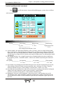
3. Pressure/Flow Slope Setting Page
After entering the correct password, press
Key once to enter Pressure/Flow Slope
Page I. The following is displayed:
Next>>
Set Pres/Flux Slope1
Act
SlowClos
FastClos
MediClos
LowClos
HPreClos
ADV.Quic
ADV.Slow
Ejec RET
P
16
16
16
16
16
16
16
16
Act
SlowOpen
FastOpen
MediOpen
LowOpen
CoreA In
CoreAout
CoreA In
CoreAout
F
16
16
16
16
16
16
16
16
P
16
16
16
16
16
16
16
16
F
16
16
16
16
16
16
16
16
NOTE GotoPressFlusSet2
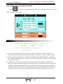
After entering the correct password, press
Key twice to enter Pressure/Flow Slope
Page II. The following is displayed:
RET<<
ACT
1LevInjc
2LevInjc
3LevInjc
4LevInjc
1LevPres
2LevPres
3LevPres
FronDecp
Set Pres/Flux Slope2
P
16
16
16
16
16
16
16
16
ACT
P
1LevFeed 16
2LevFeed 16
BackDeco 16
NozzlADV 16
NozzlRET 16
MoldThin 16
MoldThick 16
Other
16
F
16
16
16
16
16
16
16
16
F
16
16
16
16
16
16
16
16
NOTE Retunr to Engineer Set
Description on setting parameters
The Pressure/Flow Slope refers to the steep degree of rise or fall when the pressure/flow changes
from one value to the next value.“ 1” stands for the slowest change and “ 16” stands for the fastest
change. The setting range is [1-16].
R
36
Chapter 4 Instructions for the System Commissioning Settings
User's Manual for BK208S V2.0
4. Pressure Pre-Adjustment Page
After entering the correct password, press
Key once to enter the Pressure Pre-Adjustment
Page. The following is displayed:
Next>>
Coil RES.
20 W
CurrMax
10 mA
CurrMin
800 mA
PreAdjp
90 %
PressPreadj
Prea Nuse
1 10 OFF
10 20 OFF
20 40 OFF
30 60 OFF
40 80 OFF
50 100 OFF
60 110 OFF
70
80
90
100
110
120
130
140
120
160
180
200
210
220
230
255
OFF
OFF
OFF
OFF
OFF
OFF
OFF
OFF
NOTE GotoFluxpreAdj
Description on setting parameters
The pressure pre-adjustment is the linear adjustment of pressure output. In general, the standard
pressure is 0-800mA and the standard output impedance is 10-20Ω ,unless the manufacturer has specific
requirements since different manufactures' overall oil piping designs and the capabilities of the pressure
proportional valve being used are different.
Pressure Adjustment Method:
The parameters on this page have been set before ex-factory. If the capability of the proportional
valves being used by the user is different, and the normal proportion and linear proportion cannot be achieved,
the parameters on this page can be adjusted. First set the pre-adjustment to be [Activated], and then set the
pre-adjustment item to be [ON]. For example, for the 50 bar pressure position of Item 50, if the reading on
the pressure meter is 45 bar, the parameter of this item should be increased until the pressuremeter reading
reaches 50 bar. Make adjustments on all parameters which need adjusting and make the0-140 bar pressures
being set correspond to the pressures being shown on the oil pressure meter respectively.After the adjustments
are completed, the computer executes automatically linear processing and takes theprocessing results as the
subsequent normal D/A proportional output values.
R
37
User's Manual for BK208S V2.0
Chapter 4 Instructions for the System Commissioning Settings
5. Flow Pre-Adjustment Page
After entering the correct password, press
Key twice to enter the Flow Pre-Adjustment
Page. The following is displayed:
Next>>
Coil RES.
20 W
CurrMax
10 mA
CurrMin
800 mA
PreAdjp
90 bar
FluxPreadj
Prea Nuse
1 40 OFF
10 60 OFF
20 80 OFF
30 110 OFF
40 140 OFF
50
60
70
80
90
99
160
180
200
210
230
255
OFF
OFF
OFF
OFF
OFF
OFF
NOTE GotoBPressPreadj
Description on setting parameters
The flow pre-adjustment is the linear adjustment of flow output. In general, the standard value
is 0-800mA and the output impedance is 40Ω ,unless the manufacturer has specific requirements since
different manufactures' overall oil piping designs and the capabilities of the pressure proportional valve
being used are different.
Flow Adjustment Method:
The parameters on this page have been set before ex-factory. If the capability of the proportional valves
being used by the user is different, and the normal proportion and linear proportion cannot be achieved, the
parameters on this page can be adjusted. As for the speed adjustment, different manufacturershave different
measuring methods. Some manufacturers use the melt tachometer to measure the rotation speed. First heat
the barrel until the barrel temperature reaches normal melt temperature. Set the melt speed to be 1, 10, 20, 30,
and more until 99 and check the actual values. Make adjustments on all parameters whichneed adjusting and
make the 0-99% speeds being set correspond to the proportional coefficients being shown on the tachometer
respectively. After the adjustments are completed, the computer executes automatically linear processing and
takes the processing results as the subsequent normal D/A proportional outputvalues.
R
38
User's Manual for BK208S V2.0
Chapter 4 Instructions for the System Commissioning Settings
6. Back Pressure Pre-Adjustment Page
After entering the correct password, press
Key three time to enter the Back Pressure
Pre-Adjustment Page. The following is displayed:
RET<<
Coil RES.
20 W
CurrMax
10 mA
CurrMin
800 mA
PreAdjp
1
%
BPPreadj
Prea Nuse
1 10 OFF
10 20 OFF
20 40 OFF
30 60 OFF
40 80 OFF
50 100 OFF
60 110 OFF
70
80
90
100
110
120
130
140
120
160
180
200
210
220
230
255
OFF
OFF
OFF
OFF
OFF
OFF
OFF
OFF
NOTE Return to Engineer Set
Description on setting parameters
The back pressure pre-adjustment is the linear adjustment of back pressure output. In general, the
standard pressure is 0-800mA and the standard output impedance is 10-20Ω,unless the manufacturer has
specific requirements since different manufactures' overall oil piping designs and the capabilities of the pr
essure proportional valve being used are different.
Back Pressure Adjustment Method:
The parameters on this page have been set before ex-factory. If the capability of the proportional
valves being used by the user is different, and the normal proportion and linear proportion cannot be
achieved, the parameters on this page can be adjusted. First heat the barrel until the barrel temperature
reaches normal melt temperature. Set the melt back pressure to be 1, 10, 20, 30, and more until 140 and
check the actual values. Make adjustments on all parameters which need adjusting and make the 0-140
bar back pressures being set correspond to the back pressures being shown on the back pressure meter
respectively. After the adjustments are completed, the computer executes automatically linear processing
and takes the processing results as the subsequent normal D/A proportional output values.
R
39
User's Manual for BK208S V2.0
Chapter 4 Instructions for the System Commissioning Settings
7. Electronic Ruler Setting Page
After entering the correct password, press
Key three times to enter the Electronic Ruler
Setting Page. The following is displayed:
Ret<<
E.Ruler Set
E.Rule
Mete.V Leng Limi G.Orig
LMldRu Rset 250.0 400.0 375.0 Conf
InjeRU Rset
68.8 150.0 235.0 Conf
ThimRU Use
188.8 250.0 125.0 Conf
NOTE Scope:0.0---999.9
Description on setting parameters
(1) Electronic Ruler Function: If the equipment needs to use the electronic ruler, choose [Activated]. If the
equipment adopts stroke switch control, choose [Deactivated].
(2) Measurement Values: indicating the actual dynamic positions of the electronic rulers for the clamping
unit, the injection unit and the ejector.
(3) Total Length: referring to the actual lengths of the electronic rulers for the clamping unit, the injection
unit and the ejector.
(4) Limit Position: It refers to the maximum value set for the position. This parameter is subject to the
maximum position setting. For example, if the parameter set is bigger than the limit position value, the
system will not accept the parameter set and will retain the original setting.
(5) Zeroing: When the equipment choose [Activated] for the Electronic Ruler Function and uses the
electronic ruler, it may appear that the mechanic movement stroke is in place and yet the actual
positions of the electronic rulers for the clamping unit, the injection unit and the ejector do not indicate
“0” . In such case, the corresponding ruler should be zeroed. Move the cursor to the zeroing button
输 入
for [clamping unit ruler], [injection unit ruler] and [ejector ruler], and then press
Key to make
ENTER
zero clearing for the corresponding electronic ruler.
R
40
User's Manual for BK208S V2.0
Chapter 4 Instructions for the System Commissioning Settings
8.Choosing special function page
After password input correctly, press
the button, you will enter and delay
setting pages, display as follows:
Ret<<
ChosesSpecFunc
EjecEndMode Path
EjecBeginAt SliEnd
FeedMldOpen Use
FeedKeyLock Use
MotorStpSelf Use
MotorLTimeFr 50
MotoYUse
Y- Time
3.0
MdClsprt
MdClsEnd
MldClsFs
Eeyesign
StDnspUs
FeedRot
Sdmdfunc
Auto
Fspd
Way
Diff
On
Time
Nuse
DSid
Use
Note: return engineer-setting pages
The parameter setting instruction
(1) Choose the journey and the set will be stop by journey. Choose time and the set will be stopped by
time .The ways of thimble stop:
(2) You can the end mode of melt glue and the slippery-mode. Only pair slippery moulds function [meit end]
[mold end ]thimble originates: Work while choosing.
(3) Melt the glue and open the mould at the same time: When it use cool time which arrive, opening
mould needn't wait the finishing of melt and release glue.
(4) Manual press the melt glue key melt glue in succession until melt glue position or time button reach
self-lock . And then stop melting glue movements, or press once again melt-glue key to stop melting
glue movements promptly.
(5) The motor dallies and stops by oneself: the limited time set ed is effectively that the motor dally while
using.
(6) The motor racing limit time: Set range is 2-999 min, when starting, system measure is in this time, the
machine closes the motor automatically when not doing any operation, in order to protect the life-span
of motor and save the electric rate.
(7) Shut mould self-insurance: [quick][low pres]Can choose fast[quick ] , low-voltage , begin self-insurance while
choosing fast; Begin self-insurance while choosing [low-voltage ] low-voltage .
(8) Shut mould stopping : [While choosing time to the high pressure of shutting mould, high-pressure
time begins to time, time to shutting the mould to stop promptly; Choose journey and end point of
shutting mould is on ,then shutting mould promptly stop
(9) Shut mould fast: Y51 chooses guide valve to export all the time while opening themould; Choose
differential Y51 and not export while opening the mould.
(10)The slippery mould is used: Can choose pairs of slippery mould , single slipperymould , no need, this fence
function choose will decided is by display of page and using choose of slippery mould function
(11) dazzle locking: A section of way functions of the page are chosen to be locked while choosing to use
[temperature set ed ].
(12) Full-automatic: While choosing to use, the machine can run full-automatically.
R
41
Chapter 4 Instructions for the System Commissioning Settings
User's Manual for BK208S V2.0
9. Standby Function Setting Page
After entering the correct password, press
Key to enter the Standby Function Setting
Page. The following is displayed:
Next >>
ChoseBakFunc
NUSE
OutPoint Func
Y 46
Y 62
Y 66
Y 62
off
off
NUSE
Inpoint Func
X 00
X 22
X 25
X 22
off
off
NOTE Set Scope:40---73
Descriptions on setting parameters function mode
(1) Output Point Transfer Function: This function can be activated or deactivated. If activated, the output
point executes immediately transfer operation. In case that mal-function or damage occurs to a certain
point, the control can be transferred to another point by activating this function. For example, in case
that failure occurs to the mould opening output point and the knockout core function is deactivated, the
Y46 mould opening point can be transferred to Y66 and then the output wires should be exchanged.
The system is equipped with the function of simultaneously transferring two output points. Once this
function is activated, the system makes judgment on the two selected items. If the item is [ON], the
transfer of the pre-set conditions of the item will be executed.
(2) Input Point Transfer Function: This function can be activated or deactivated. If activated, the input
point executes immediately transfer operation. In case that mal-function or damage occurs to a certain
point, the control can be transferred to another point by activating this function. For example, in case
that failure occurs to the front safety door input point and the knockout core function is deactivated,
the X00 front safety door input point can be transferred to X25 and then the input wires should be
exchanged. The system is equipped with the function of simultaneously transferring two input points.
Once this function is activated, the system makes judgment on the two selected items. If the item is
[ON], the transfer of the pre-set conditions of the item will be executed.
R
42
Chapter 4 Instructions for the System Commissioning Settings
User's Manual for BK208S V2.0
10. Programmable Standby Function Page
After entering the correct password, press
Key twice to enter the Programmable Page.
The following is displayed:
Ret<<
PragBckPoint
NUSE Y 73 AT
ACFL
SegOut
NUSE Y 72 AT ABCDEFGHIJKLMNOP SegOut
NUSE Y 71 AT
FL
SegOut
NUSE Y 70 AT
C
SegOut
NUSE Y 67 AT
CD
SegOut
NOTE
Set Scope:40---73
Descriptions on setting parameters function mode
In order to meet diversified application needs and provide an innovative product, we take the
initiative to offer the programmable standby function page so that the users can define and revise by
themselves the functions and the action sequence.
Example 1: For a certain mould injection machine, due to the different design of the oil piping, it
is required that a point is output while clamping at high pressure and the power will not be interrupted
until the melt finishes taking out. To achieve such a special function, choose an item and have it activated,
and then specify an output point (i.e. this function is output through Y xx), and then set the action
sequence [CD].
Notes: Regarding the output scope of Sequence D Clamping Stop, in automatic mode, the clamping
switch is contacted during the process of mould close at high pressure, and this sequence output starts
until the melting finishes; in manual mode, the clamping switch is contacted during the process of mould
close at high pressure, and this sequence output starts until the mould opening key or the reset key is
pressed.
Example 2: For a certain mould injection machine, due to the different design of the oil piping, it
is required that a point is output while injecting and melting. To achieve such a special function, choose
an item and have it activated, and then specify an output point (i.e. this function is output through Y xx),
and then set the action sequence [FH].
R
43
Chapter 4 Instructions for the System Commissioning Settings
User's Manual for BK208S V2.0
11. Temperature Parameter/Time Setting Page
After entering the correct password, press
Key to enter the Temperature Parameter/Time
Setting Page. The following is displayed:
Ret<<
Set temp./Time Prams
P
Ejec Use 50
1Seg Use 50
2Seg Use 50
OilTAlrm
D
50
50
50
P
3Seg Use 50
4Seg Use 50
5Seg Use 50
Use
Max
D
50
50
50
80
03 Y 01 M 01 D 18 H 08 M 58 S
Wed.
NOTE Retunr to Engineer Set
Descriptions on setting parameters function mode
(1) Nozzle Function: [Activated] or [Deactivated] can be chosen. If deactivated, the system will not
execute inspection and control on this sequence.
(2) Sequence I Function: [Activated] or [Deactivated] can be chosen. If deactivated, the system will not
execute inspection and control on this sequence.
(3) Sequence II Function: [Activated] or [Deactivated] can be chosen. If deactivated, the system will not
execute inspection and control on this sequence.
(4) Sequence III Function: [Activated] or [Deactivated] can be chosen. If deactivated, the system will not
execute inspection and control on this sequence.
(5) Sequence IV Function: [Activated] or [Deactivated] can be chosen. If deactivated, the system will not
execute inspection and control on this sequence.
(6) Sequence V Function: [Activated] or [Deactivated] can be chosen. If deactivated, the system will not
execute inspection and control on this sequence.
(7) Oil Temperature Selected: [Activated] or [Deactivated] can be chosen. If deactivated, once it is
detected that the oil temperature is equal to or over the set upper limit, the alarm will be neglected.
If activated, the alarm will be output, and the system will turn to manual mode and the motor will be
turned off when the alarm cycle ends.
(8) Pd Setting: Pd has been set before ex-factory. It is recommended that the user should not revise this
parameter under normal circumstance.
R
44
User's Manual for BK208S V2.0
Chapter 4 Instructions for the System Commissioning Settings
12. Machine No./Ex-Factory Value Setting Page
After entering the correct password, press
Key to enter the Machine No./Ex-Factory
Value Setting Page. The following is displayed:
Ret<<
MachinCode/SetFacVal
Machine Code
PS-999999999
Revert Fac.Value
Confirm
NOTE Retunr to Engineer Set
Descriptions on setting parameters function mode
(1) Mould Injection Machine No.: The system is equipped with the function of setting NO. for the mould
injection machine so that the manufacturer can set the No. for easy sales management and after-sales
service record.
(2) Ex-Factory Value Restoration: During the modifying process of password pages, if normal operation
cannot be achieved due to too much deviations of the modified parameters, press Key Enter and
choose Confirm, and then all the contents and all the parameters will be restored to the standards valu
es set before ex-factory.
R
45
Chapter 5 Input/Output Mode Inspection
User's Manual for BK208S V2.0
Chapter 5 Input/Output Mode Inspection
1. Input Inspection Page
(1) Press
Key on the Main Page to enter Input Inspection Page I and the following will be
displayed:
2003.1.2
Input Check1
X10 QuicOMld
X11 OMld2Slw
X12 OmldStop
X13 ThimFStp
X14 ThimBStp
X15 Rote2
X16 RoteSp2
X17 2LevShot
X00 Bsafedoor
X01 LPreLmld
X02 Hprelmld
X03 LMldStop
X04 ShotDiaFS
X05 Rote1
X06 RoteSp1
X07 ShotDiaBS
NOTE:<
(2) Press
15:32:15
--Ninput/
--Input>
Keyon the Main Page to enter Input Inspection Page II and the following will be
displayed:
2003.1.2
Input Check2
X20 3LevInje
X21 Mi.M F.S
X22 Mi.M b.S
X23 Mani C.M
X24 Mani Thi
X25 In.C A S
X26 Ou.C A S
X27 MotorOvld
15:32:15
X30 In.C B S
X31 Ou.C B S
X32 Litteroil
X33 +10VG
X34 MldclsRu
X35 Injectru
X36 Ejectru
X37 10VG
< --Ninput/
NOTE:
--Input>
R
46
Chapter 5 Input/Output Mode Inspection
User's Manual for BK208S V2.0
(3) Press
Key on the Main Page to enter Key Inspection Page I and the following will be
displayed:
2003.1.2
Key Inspection 1
ManuMoldOpen
SLowSpeed
ManuMoldClose
ManuInjection
Auto Mold1ADJ.
Manu Decomp
ManuFeeding
AnuEjectRet
ManuPurge
ManuEjector
ManuEjectAdv
ManuNozzleAdv
ManuLlow
ManulubrIct
ManuNozzleRet
ManuBlwFmale
NOTE < --Ninput/
(4) Press
15:32:15
--Input>
Key on the Main Page to enter Key Inspection Page II and the following will be
displayed:
Key Inspection 2
15:32:15
2003.1.2
MidAdjSekect
MANUAL
ManuMIdAdjRet
SEMI.AUTO
Manumidadjadv
Auto
UrgeReset
CORE A IN
CORE A OUT
HEATER ON/OFF
CORE B IN
MOTOR ON/OFF
CORE B OUT
Data lock
UrgeStpOn/Off
NOTE <
--Input>
--Ninput/
The above input inspection pages are used for signal inspection and cannot accept information
modified. The solid box on the display indicates that the signals are being input.
R
47
Chapter 5 Input/Output Mode Inspection
User's Manual for BK208S V2.0
2. Output Inspection Page
(1) Press
Keyon the Main Page to enter Output Inspection Page I and the following will be
displayed:
2003.1.2
Output chec1
Y50 Djectret
Y40Moldclose
Y41NozzleAdv
Y42Injection
Y43Feeding
Y44Decomp
(2) Press
displayed:
15:32:15
Y45Nozzleret
Y46MoldOpen
Y47EjectAdv
Y51 MoldThin
Y52 Diff L.M
Y53 Rote
Y54 Rote Slw
Y55 Reserve
Y56 LPMldCls
Y57 HPMldCls
NOTE: <
--OutPut>
--NotOut/
Key on the Main Page to enter Output Inspection Page II and the following will be
2003.1.2
Output chec2
15:32:15
Y60FaultAlarm
Y61BPump
Y70Back
Y62MPump
Y72BlowMale
Y63MldOpnBuff
Y73BlowFmale
Y64CoreBin
PressIndi
Y65CoreBout
Y66CoreAin
FluxIndi
MoldAdj
Y67CoreAout
AutoPurgelIndj
NOTE: <
Y71back
--NotOut/
--OutPut>
R
48
Chapter 5 Input/Output Mode Inspection
User's Manual for BK208S V2.0
(3) Press
Key on the Main Page to enter Output Inspection Page III and the following will be
displayed:
2003.1.2
Output chec3
15:32:15
T0T0Eject
ManuIndi
T1Seg1
SemiAutoIndj
T2Seg2
T3Seg3
AutoIndj
UrgeResrt
T4Seg4
HeaterIndj
T5Seg5
Motor Indj
MoldADjIndi
Motor
Ymotor
MAutoMIdAdini
NOTE: < --NotOut/
--OutPut>
(4) The above output inspection pages are used for signal inspection and cannot accept information
modification. The solid box on the display indicates that the signals are being output.
Notes:
All the input and output point pages in this instruction manual are subject to changes without notice.
The inspection pages displayed on the computer should be correct and final.
R
49
Reference & Appendices
User's Manual for BK208S V2.0
185
32
15.5
5
5
119.5
17.5
17.5
345.5
405
18.5
45
18
20.5
10.8
R6
8
8
68
12.8
22.8
26
62
44
4
55
BK208S Keyboard Installation Size Diagram
R
50
Reference & Appendices
User's Manual for BK208S V2.0
5
6
PW 60 0
Power Supply Case
112
124
132
120
145
215
Figure of Dimensions & Installation Hole Positions
for Power Supply Case
5
6
8
220
190
202.5
PS 800C M
50
188
288
208
50
Figure of Dimensions & Installation Hole Positions for Master Machine
R
51
Reference & Appendices
User's Manual for BK208S V2.0
A j2
R
52
Aj1
Reference & Appendices
User's Manual for BK208S V2.0
X00
X01
X02
X03
X04
X05
X06
X07
紧急上升
低压锁模
高压锁模
锁模停止
电眼输入
熔胶停止
滑模右停
右滑慢速
X10
X11
X12
X13
X14
X15
X16
X17
左合模输入
右合模输入
开模停止
左顶针前停
左顶针后停
滑模左停
左滑慢速
二段射出
压力比例阀线圈
速度比例阀线圈
背压比例阀线圈
右模吹气
左模吹气
备用
备用
定位下
定位上
出牙
入牙
大泵
警报
右顶退
右顶出
X20右顶针前停
X21右顶针后停
X22定位上限
X23机械手合模
X24机械手顶针
出芯
入芯
右滑模
机械手讯号
左滑模
高压锁模
开模卸荷
左顶退
X25入芯停
X26出芯停
X27马达保护
左顶出
开模
座退
射退
储料
射出
座进
锁模
X30三级射出
X31射出检测
X32座进停止
锁模尺
射出尺
滑模尺
R1
油温
四段
M
Y
三段
二段
一段
射咀
PORCHESON
PS800CM
SSR Input & Output Wiring Diagram
R
53
HC5
HC4
HC3
HC2
HC1
HC0
Reference & Appendices
User's Manual for BK208S V2.0
Keyboard wire connection
Red black orange black
yellow grey blue purple
system running
24V power supply input
X00 pending upswing
X01 low pressure mold closing
X02 high pressure mold closing
X03 mold closing stop
X04 electronic-eye input
X05 stopping melting plastic
X06 right stopping mold-slide
X07 right slide relent speed
X10
X11
X12
X13
X14
X15
X16
X17
Pressure
Speed
for proportionalvalve of pressure
for proportionalvalve of pressure
back pressure
blowing of ritht mold
blowing of left mold
Spare
Spare
for proportionalvalve of back-pressure
lay-align
sur-align
whorl out
whorlin
large sizepump
alarming
right-retraction of thimble
right roofout
Left mold-closing with output
right mold-closing with input
mold-openning stopping
pre-stopping of left-thimble
stopping retraction of left-thimble
Left hait of slid mould
left slid slow
shot second section
core out
core in
right slidemold
signal forrobot arm
left slide mold
high pressuremold closing
upwrap mold to dismantleburden
left-retraction ofthimble
X20front halt of right
X21black halt of right
X22 align sur-limitation
X23 mold-closing with robot arm
X24 thimble with robot arm
X25 core in stop
X26 core out stop
X27 engine protection
core out left
mold openning
retraction of nozzle
shootdrop out
deposit material
shootout
forwarding nozzle
mold closing
X30 triple pole plastic injection
X31 plastic injection detection
X32 forwarding nozzle stop
ruler for mold closing
ruler for plastic injection
Ruler for slid mould
R1
stage 4
M
stage 3
stage 2
SSR6
stage 1
SSR5
SSR4
Nozzle
SSR3
SSR2
SSR1
PORCHESON
PS800CM
PS8 00CMInput & Output Wiring Diagram
R
54
Slubricating the engine
M-oil-driven engine
R1Standby
Stage5
Stage4
Stage3
Stage2
Stage1
Nozzle
Reference & Appendices
User's Manual for BK208S V2.0
R
55
Reference & Appendices
User's Manual for BK208S V2.0
R
S T
3 POWE R MCB
Absorption
Component
N
MC1
Absorption
Component
Coil Interference Absorption
N
Contact Interference Absorption
O.L
Absorption
Component
Motor End Interference Absorption
MOTOR
Common Interference Suppression Method (for reference only)
R
56