1
User's Manual for TB108 V2.0
Preface
Welcome to use Our Injection Molding Machine Control System
Safety Cautions
(Please read it before installation)
1.In order to ensure the secure operation of the whole system in
Danger
case of the abnormal external power and the control system's
failing to function, please set up the external safe circuit for the
control system.
2.Upon its failure to detect the abnormal conditions of input and
output, the control system cannot control the output. Therefore,
please design the external circuit and frameworkto ensure the
safe operation of the system.
1.Please read this User's Guidance carefully before installation.
2.Do not dismantle the host computer shell and keyboard
Cautions
without permission.
3.In case of any questions, please dial the after-service service
hotline of PORCHESON.
Prompt
1.with the update of the system ,any changesabout its
products and services at any time will be without notice.
2.welcome to comment it if there is any defects about it。
R
Ⅰ
User's Manual for TB108 V2.0
Contents
Declaration
Please read this manual before you use the system.PORCHESON
assumes liability for the problems from the system itself. As a
result of improper operation ,maintenance without authorization ,
natural disasters ,as well as the failure caused by natual disasters,
or other unusual circumstance ,the system is damaged or the data
is lost , PORCHESON is not responsible for it .
PORCHESON reserves the right to make corrections ,modifications,
enhancements,and other changes to its products and services at
any time and to discontinue any product or service without notice.
The contents of this maual is only for reference as we may have
different understanding,we won ’ t be liable for any losses cause by
misuse of this manual.As reference to the graphic description,there
may be some discrepancy and error ,but its function is shown in the
match.
PORCHESON is accordance with the copyright law,have and retain
all of the exclusive right.Without the written authorization,any
addition,deletion ,modifiction,reproduction and imtation is not
permissible.
R
Ⅱ
User's Manual for TB108 V2.0
Contents
PORCHESON
TECHNOLOGY CO.,LTD
System Configuration
& Installation
1
Explanation of the Key
Operations
4
Descriptions on setting
parameters/functions
11
TB 108
Operator's Manual
Product Management
31
Software Version: V2.0
System Debug Setting
Input/Output Mode
Inspection
37
50
2 0 0 8. 1 0 Version
Reference & Appendices
52
All copyrights are reserved, any duplication without the prior authorization shall be
forbidden.
R
III
User's Manual for TB108 V2.0
Contents
Contents
Chapter 1: System Configuration&Installation
1、System Configuration&Explanation--------------------------------------page 1
2、Characte ristics of PS6 60BM Control Sys tem-----------------------------page 1
3、Installation and Debugging of Computer Control System---------------page 2
Chapter 2:Explanation of the Key Operations
1、Figure of Keyboard on the Operation Panel (See the figure below)----page 4
2、Explanatio n of the Funct ion Key ------------------------------------------page 5
3 、E xpl anation of t he Para meter setting-------------------------------------- page 6
4、Cursor Key-------------------------------------------------------------------page 7
5、Operation Mode Selection K ey---------------------------------------------page 7
6、El ectrothe rma l ON /O FF key a nd Motor O N/O FF key--------------------pa ge 7
7 、M anual Op eration keyboard------------------------------------------------page 8
8、Setti ng scope of Numeric Items------------------------------------------- page 10
Chapter3:Descriptions on setting parameters/functions
1、The comm on-hompage w hile turning on---------------------------------- page 11
2、The C-machinery's homepage while turning on---------------------------pag e 12
3、Fast Setting Pa ge -----------------------------------------------------------page 16
4、Set mould Opening and Close information--------------------------------page 17
5、Set plastic injec ting/ blo wing informati on-------------- ------------------p age 18
6、Set the stuff storing and cleaning information----------------------------page 19
7、Set Noz zle a nd E ject ion i nformati on-------------------------------------page 20
8、Set Slide mold and Location inform ation---------------------------------page 21
9、Set neutron/cutter teeth information---------------------------------------page 22
10、S et tim e/coun t informatio n-------------------------------------------------page 23
11 、Se t tempe rature i nformation-----------------------------------------------pa ge 24
12、Set wa rm-up info rmation---------------------------------------------------page 25
13、Se t m ou ld informa tion------------------------------------------------------pa ge 26
14、Record of data modification-----------------------------------------------page 27
15、Adjust/S et special parameters---------------------------------------------page 28
R
IV
User's Manual for TB108 V2.0
Contents
Chapter 4:Production Management
1、Production Data setting page ----------------------------------------------- page 31
2、SPC tracing record Page ---------------------------------------------------- page 32
3、Pressure Speed curve drawing page --------------------------------------- page 33
4、 Temperature tracing curve drawing page --------------------------------- page 34
5、Alarming record page ----- ------------------------------------------------ page 35
6、USB setting page ----------------------------------------------------------- page 36
Chapter 5:Instruction for the System Debugging Settings
1、Engineer setting page------------------------------------------------------- page 37
2、Delay Setting Page---------------------------------------------------------- page 38
3、Pressure/ Flow Slope Setting page---------------------------------------- page 39
4、Pressure Pre-Adjustment page--------------------------------------------- page 40
5、Flow Pre-Adjustment page ------------------------------------------------ page 41
6、Back Pressure Pre-Adjustment page--------------------------------------- page 42
7、Electronic Ruler/Pressure Inspection setting page----------------------- page 43
8、Special Function Option page---------------------------------------------- page 44
9、Standby Function setting page--------------------------------------------- page 46
10、Programmable standby Function page----------------------------------- page 47
11、Temperature Parameter/Time setting page------------------------------ page 48
12、Machine No./Ex-Factory Value Settiong Page-------------------------- page 49
Chapter 6:Input/Output Mode Inspection
1、Input Inspection page------------------------------------------------------- page 50
2、Output Inspection page----------------------------------------------------- page 50
Reference&Appendices
1、TB108 keyboard installation dimension drawing ------------------------ page 52
2、TC108 keyboard installation dimension drawing------------------------ page 53
3、Exterior dimensions and installation hole position drawing for
switching power supply case ---------------------------------------------- page 54
4、Exterior dimensions and installation hole position drawings for
mainframe ----------------------------------------------------------------- page 54
5、System wiring drawing------------------------------------------------------ page 55
6、Motor heating wiring drawing---------------------------------------------- page 56
7、Usual methods of interference suppression------------------------------- page 57
R
V
Chapter 1 System Configuration & Installation
User's Manual for TB108 V2.0
Chapter 1 System Configuration & Installation
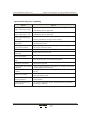
1. System Configuration & Remarks
No.
Configuration
Mode
Quantity Remarks
PS660BM 24/24+7 +3 path electronic rule
1 set
Optional
PS860BM 31/28+10 +3 elecrronic rule
1 set
Optional
TB 108
LCD 7 .0" TFT
1 set
Optional
TC 108
LCD 7.0" TFT (Touch panel)
1 set
Optional
3.Power
PW 600
600W
1 set
4.Communication Cable
DB-15F
1M- 8M optional
1 set
1.Host computer
2.Keyboard
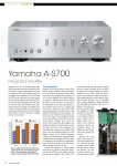
2. Characteristics of PS860BM Control System
The system has bright LCD display and 800*480 Dot 7 " colorful
The system adopts double 32bit CPU design with fast operating speed, precise control and high stability.
It has the real time function to display time and date in real time.
With 999 groups of mode data storage, it may enter the model description and real-time operating
help in Chinese and English.
The password setting and data locking can prevent the operators from changing the established data
arbitrarily to influence the quality of products.
There are multiple languages for your choice that display dynamically in real time.
Packing modulus setting function for 8-digit output may set the packing modulus.
PID (Proportional Integral Derivative) with self temperature control has 6 +1 sections of temperatures.
Temperature may be preset a week in advance to enable more convenient operation.
Input and output have overloaded and short circuit protection.
Failure Self-detection functions, alarm display and voice prompt
Input and output are done by the optically coupled circuit to isolate the interference of the
external circuitry.
LED indicators for output and input may it convenient to inspect and maintain the system.
In the inspection window, you can inspect all input and output points and the moving states of key.
3-path standard D/A proportional output, the maximum current output 3A (PS610 is 2-path).
The output of pressure, speed, current can be monitored real time.
Presetting of the voltage ,flow and pressure, proportional valve available for the products in all
brands and better linear proportion.
With remote communication functions, it can let you do the programming and upgrading
softwares easily and remotely.
The management of 255 vertical machine production is by a host networking computer ,
It can accurate statistics each machine production state and produce data type ,so ,it is
convenient to manage.
R
1
Chapter 1 System Configuration & Installation
User's Manual for TB108 V2.0
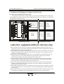
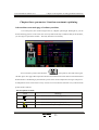
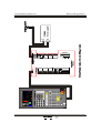
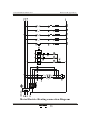
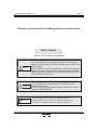
3. Installation and Debugging of Computer Control System
3.1Cautions upon Installing the Control System
The design of control system is simple and easy, only one 15-core shielding cable connecting the
keyboard and host computer shell with flexible and handy installation and connection. The sketch map
for installation is shown as follows:
P W 6 00
X00
X01
X02
X03
X04
X05
X06
X07
P OWER
Control
system.
POWER
Strong
eletricity
Equipment
X10
X11
X12
X13
X14
X15
X16
X17
X20
X21
X22
X23
X24
X25
X26
X27
X30
X31
S t r o ng
Relay
board
e le tr i ci t y
E qu i p me nt
Strong
eletricity
Equipment
P S 66 0 B M
Ebb eletricity section
Strong eletricity section
control box equipment;outfit (for reference only)
(1)Upon installing the host control box, adopt the enclosed distribution cabinet at the first choice. It
shall be fixed in the well-ventilized, greaseproof and dustproof conditions equipped with a fan and
The distribution box shall be stored under 60 ℃.
(2)Upon fixing the host computer and power pack, please keep the interconnecting parts such as all AC
connectors and transformers as far away from each other as possible to prevent the electric wave
interference from the electronic grid.
(3)All electric wires and shielding wires shall not be cut off, lengthened or curtailed arbitrarily. You
should use the electric wires and shielding wires provided by this company to prevent from
influencing the reliability and normal operation of the control system.
(4)The shell of flame couple shall adopt the shielding wire. When the outer shielding of all flame
couples adopts the thermal couple reticles, the reticle and machines shall be well grounded and
connected to the ground with the earthing resistance below 10 Ω.
(5)Upon wiring, separate the high and low pressure line from the computer control line as much as
possible, do not bind all electrical wires together to prevent the interference from affecting the
reliable operation of control system.
(6)Upon fixing the keyboard and 15-core communication connections of the host computer, you shall
press and tweak with force to prevent the poor connection from affecting the reliable operation of
control system.
(7)Pay special attention to the oil valve outlet public port YCOM, it shall be connected well to prevent
the computer from inputting while having the phenomenon of oil valve having no motion.
R
2
Chapter 1 System Configuration & Installation
User's Manual for TB108 V2.0
3.2 the examine of controlling system
(1) After finishing installing, check in an all-round way, ensure all such lines including switch power,
host computer case, electric heat output circuit , keyboard electric thermocouple ,etc. join firmly .
(2) After Finish circuit checking , it should check electify , output direct current source namely switch
power line plug take out first, then check to set up an electric circuit , measure every voltage see that
it is the same as the standard value , should observe if switch power output indicator lamp normal.
(3) Cut out the electric after finish the measurement, insert DC8 location input the host computer case
plug , process electrify check-up .when checking again.the keyboard LCD show in main page in
normal condition,turn on park switch and check if the host computer case RUN light is on, if the
light is on, prove the system has already worked normally.
3.3 control systems debugging
(1) After System show the normal work , press
1
STU
Key,the model button under supervise page,
choosea groupof mould number , then establish in every page.
资 料
(2) Carry on the parameter establish memory test, press
DATUM
Key , the button on the data, press
输 入 Key, then store the data, cut off the power , put power on after a while , the system will access
ENTER
the model number materials that you store in automatically , if correct, show memory is normal.
(3) Go on establish of every relevant page materials, (particular oprating refer to the parameter enactment
instruction of the third charper .while establishing for the first time, the pressure , speed have better
be a bit more low , strengthen normally progressively after every movement is normal, so as not to
damage the performance of the machine.
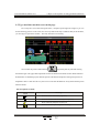
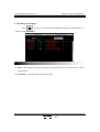
(4) After finished relevant parameters established, you should enter the store and check carefully whether
it is normal to each input / export point, checks the warning system in an all-round way, including the
electric eye , going up promptly; the wiring diagram of shut model button going up promptly as follows
promptly.
Shut model Shut model
button righ 1 button right 2
Shut model Shut model
button left 1 butto left 2
XCOM
XCOM
X10
X11
Going up promptly button.
XCOM
X 00
(5) Left and right shut model button push time difference exceed 2 second , system will alarm, stop all
outputting at the same time; Push the system of going up promptly and stop exporting immediately,
output the open model movements at the same time , operate model chang to by hand .
R
3
Chapter 2 Explanation of the Key Operations
User's Manual for TB108 V2.0
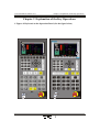
Chapter 2 Explanation of the Key Operations
1. Figure of Keyboard on the Operation Panel (See the figure below)
U SB-b us
R
4
Chapter 2 Explanation of the Key Operations
User's Manual for TB108 V2.0
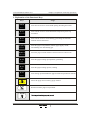
2. Explanation of the Functional Keys
Keys
开锁模
Usage
Enter into the screen to set the mold opening & locking movement
M.PLT
射 出
INJECTION
储 料
FEEDING
座 台/托 模
NOZZ/EJE.
滑模/中子
Enter into the screen to set the Glue Shot and pressure-preserving
movement
Enter into the screen to set the feeding, glue taking and automatic
material removal movement
Enter the page of seat platform, thimble, page slippery model,
and releasing core and releasing gas.
Enter the page of slide module .location neutron cutter teeth
TABLE/CORE
时 间
Enter the page of setting up temperature, preheating
TIME
温 度
TEMP.
资 料
Enter the page of setting up time, counting
Enter setting up and modification page of mould and production material
DATUM
快速设定
Enter the page of Fast setting page I and II
CELERITY SET
监 视
Return to monitor pages at any moment
MONITOR
帮 助
HELP
R
5
Chapter 2 Explanation of the Key Operations
User's Manual for TB108 V2.0
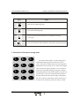
Keys
Usage
PC连 接
Enter into the USB setting page
PC LINK
诊 断
Enter into the alarming page
DIAGNOSE
曲 线
Enter into the Pressure-Speed curve ,Temperature tracing
curve page
CURVE
生产管 理
Enter into Production data modification setting ,SPC tracing record page
FLOW CHART
3. Instruction of Parameter setting mode
7
ABC
8
DEF
9
GHI
used for data importing, when the electronic lock is in
" OFF " state, this ten numerical keys are locked, guarantee
4
5
6
1
2
3
JKL
STU
MNO
VWX
The numerical key from0 to 9 in data setting page is
PQR
the materials not to be altered at will . There are 26 English
letters and special symbols separately on 0 to 9 numerical
keys for the mould name inputting in Chinese or English,
YZ
the inputting machine serial number. [Remove key] you can
press this key to remove the wrong when the parameter or
清 除
CLEAR
0
the serial number name have been wrongly written[Input]
[ ]/ -.
key serve as function selection key if there are functions to
be select and as confirm key if there are items to confirm.
R
6
Chapter 2 Explanation of the Key Operations
User's Manual for TB108 V2.0
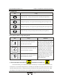
4. Vernier key
Keys
Usage
Jump rank key, cursor goes the previous line after pressing this key
Change arrange key, cursor goes the left arranging after pressing this key
Change arrange key, cursor goes the right arranging after pressing this key
Jump rank key, cursor goes the previous line after pressing this key
5.the options button of operating mode
Keys
手 动
MANUAL
半自动
SEMI.AUTO
全自动
AUTO
Usage
Remarks
There is an indicator at the upper
left corner of every key,after pressing
state after press the button.
one of these key,this indicator is on,
that showthe system is in the just state.
The default mode is manual operation.
S Press this key and system enters the If temperature hasnot reached the
establishing value , the system is
semi-automatically operation
unable to operate semi-automatically,
when pressing buttons as semi-autom
atically, the indicator lamp is not on.
Press this key and s system to enter the Untiltemperature reaches the establ
full-automatically operation
ishing value, the set can run
semi-automatically .
System enter the manual operation
6. Electrothermal ON/OFF key
and Motor ON/OFF key
In the manual mode, press a button the indicator in the left up is on which indicates this function has
already been on; the indicator lamp left above is off when press the button once again ,shows this function
state has already been closed , continue press the key, this function will be opened or closed in turn. When
the emergency switch stops, the motor cuts out rapidly, but does not influence the electric heat work.
R
7
Chapter 2 Explanation of the Key Operations
User's Manual for TB108 V2.0
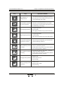
7. Manual operation key
Keys
Operation Conditions
Usage
开 模
Open mould operate
1 . turning on mould don't reach stop position;
MOLD OPEN
射 出
1. press keeping time has not ended;
jet operate ion
2. the temperature of the material tube must reach
to the establishing value range;
INJECT.
射 退
Jet back operation
1. the temperature of material tube already reached
the establishing value range;
SUCK BACK
Tip out operation
1. if using the journey, the journey has not reached the
position of stopping;
2. If using time, the time of appearing and has not
ended;
3. the opened-mould already got the position of stopping;
4. if using releasing core /entangling, produce /already;
Core retreat tooth finish
5. if using slippery mould, Left or right slippery mould
has already got to make a reservation;
Retreating operation
1. if using the journey, the journey has not reached
the position of stopping ;
2. if using time, the time of retreating has not ended ;
托模进
EJECT ADV.
托模退
EJECT RET.
座台进
The operation of seat
move forward
1 . unconditional;
NOZZLE ADV.
座台退
The operation of seat
move back
1 . unconditional;
NOZZLE RET.
调 模
The operating of
adjusting mould
1. the speed of t adjusting he mould to slow down
after pressing this key bright;
MOLD ADJ.
吹 气
The blowing operation
BLOW
1. chooses for blowing;
2. Blow time has not ended;
R
8
Chapter 2 Explanation of the Key Operations
User's Manual for TB108 V2.0
Keys
储 料
Usage
The operation of
adding material
SCREW ROTATE
自动清料
AUTO PURGE
Left slipping operation
TABLE LEFT
PRESS TEST
定位进/+
3. right slipping model has not got the end location
The pressure adjusting
operation in advance
Back orientation/ pressure
increasing
L.UP/INC.
定位 退/-
Back orientation/ pressure
minishing
L.DOWN/DEC.
绞牙进
SCREW ADV
绞牙退
1 .after pressing this bright key, you can enter the
pressure adjusting operation
1. not choose the pressure-reservation ; realize the
advance orientation operation
2. already choose the pressure-reservation; Realize
the increasing-pressure operation
1.not choose the pressure-reservation ; realize the
advance orientation operation
2. already choose the pressure-reservation; Realize
the monishing-pressure operation
1.choose to use
wringing tooth operation 2.advance-time not end
3.stop retreating
Retreat wringing tooth
operation
SCREW RET
1. stop opening mould
2.stop retreating;
3. left slipping model has not got the end location
1. stop opening mould
Right Slipping operation 2. stop retreating;
TABLE RIGHT
压力测试
1 . not reach end position for adding raw material
2.The temperature of the material tube must reach
in the establishing value range;
1. chooses for clearing material;
The automatic operation 2. The times of clearing material has not ended;
3. the temperature of the material tube must reach in
for clearing material
the establishing value range;
左滑模
右滑模
Operation Conditions
1. Choose to use
2. advance-time not end
3. Stop retreating
R
9
Chapter 2 Explanation of the Key Operations
User's Manual for TB108 V2.0
Keys
中子进
Enter core operation
CORE IN
中子退
Output core operation
CORE OUT
多次托/润滑
Operation Conditions
Usage
紧急停止
1. choose to .releases the core
2. the entering- core not to ending position or;
Time has not finished
3. stop retreating
1. choose to .take out the core
2. the outputting- core not to ending position or;
Time has not finished
3.stop retreating
Ejection
lubrication
1、the operation condition is same as ejection;
2、the setting time of ejection is not up;
3、lubrication count is not zero;
Mold close
紧急停止
1、X00 input normal;
2、electronical eye input normal;
3、ejection retreat or the time is up;
4、mold close is not in the terminate or the time
is not up;
5、L or R sliding mold are oriented
6、oriention in is stoped
EJECT./ LUBR.
合 模
MOLD CLOSE
8. Setting Scope of Numeric Items
Number
Setting Items
Setting Scope
1
Establishing the pressure
Digita≤l999.9
2
Establish the speed
Digital≤ 140
Bar
3
Establish temperature
Digital≤ 99
%
4
The mould materials storing
Digital≤999Max70 0C
for actu al use Centig arad e
℃
5
Establish jet out position
Digital≤999.9
mm
6
If the establishing value
beyond thescope of the above,
Digital≤999.9
mm
7
Storage of mold data
Digital≤5999.9
mm
8
Book the output
Digital≤ 80
9
Establish Lock mould position
Digital≤999999
Unit
Second
Number
PC
In case of the set values exceed the above-mentioned scopes, the system will not accept the numbers
set and keep the original set values. For the habit of data input, the data input of this system is display
from right to left.
R
10
User's Manual for TB108 V2.0
Chapter 3: Descriptions on setting parameters/functions
Chapter three: parameter / function enactment explaining.
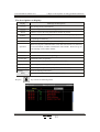
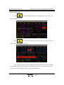
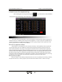
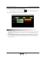
1.the machine-start main page of ordinary machine,
Urn on the power ,turn round red urgent switch , computer operate light RUN light on ,you can
see the following pictures on the screen, the control system has already worked normally at this moment,
you can begin to operate the machine . The ready machine runs normally.
You can enter the picture of the machine
when push any time after starting the
machine again. This page offer temperature monitor and machine movement monitor. Mould nameand
mould number is establishing by the materials picture of the mould. Temperature arranges and present
oil temperature shows actual value of every sections. You can't alter the materials. Every functionof the
picture stated as follows:
The descriptions on mode:
Meanings
Mode
Show the motor has already operated;
Show the electric heat has already been opened;
Show lubricate-pump that is pump oil;
Show the electric eye is imported normally;
R
11
Chapter 3: Descriptions on setting parameters/functions
User's Manual for TB108 V2.0
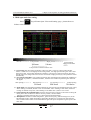
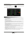
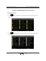
2.C Type machine machine-start main page
Urn on the power ,turn round red urgent switch , computer operate light RUN light on ,you can
see the following pictures on the screen, the control system has already worked normally at this moment,
you can begin to operate the machine . The ready machine runs normally.
You can enter the picture of the machine
page when push any time after starting
the machine again. This page offer temperature monitor and machine movement monitor. Mould nameand
mould number is establishing by the materials picture of the mould. Temperature arranges and present oil
temperature shows actual value of every sections. You can't alter the materials. Every functionof the picture
stated as follows:
The descriptions on mode:
Meanings
Mode
Show the motor has already operated;
Show the electric heat has already been opened;
Show lubricate-pump that is pump oil;
Show the electric eye is imported normally;
R
12
User's Manual for TB108 V2.0
Chapter 3: Descriptions on setting parameters/functions
The descriptions on display:
Display
Meanings and descriptions
Manual
The running mode of the machine;
Second
sections it express this section is being heated;
Mould
number it express the using-model Serial number at present;
Produce
At present
Whole
in advance; it expresses setting value of the times mould-opening at present ;
Remember g the mould-making times of the mould at present in the course
of operating automatically;
process the system operates cycle-time actually;
When carrying have established time value, data will increase to it, then carry
Operation
on next movement, if number established is times number. Shows will go on
until reaching value of times number ;
Settlement
the time value or counter value of operating ;
Pressure
pressure-established evalue of operating ;
Flo the flow-
established value of operating ;
Lock mould
show locking mould position at present, the unit is mm ;
Slippery mould
Spiral shell's pole
The machine runs
normally
Ready
shows slippery model's position at present, the unit is mm ;
shows the present spiral shell's pole position, the unit is mm ;
Show the warning content now ;
Show the movements of the machine operates now ;
诊 断
Re-press
DIAGNOSE
key to show the following menus
R
13
User's Manual for TB108 V2.0
Chapter 3: Descriptions on setting parameters/functions
Descriptions on alarm mode
Alarm
Source
Solution
ThisX04 terms message show When Check whether the electricity is
The electric eye
electric eye Input have no signal;
correct and electric eye is hidden
But the alarm is being only made
is unusual
or lost efficiency long.
only when shutting the mould .
check whether unusual in shutting
Shut the mould has not Fail to finish shutting mould movem mould course, if normal you should
ents in “ shut the mould to prescribe transfer longer the“ shut mould
finished regularly
a time limit” .
prescribes a time limit”.
Protect-mould time in
low-voltagly arrive,
If low-voltage time arrives, warning Check whether mould have incidental,
you can transfer longer “ low-voltage
not transferred high-voltage yet.
time ”if possible.
Warning when X00 has no signal Please check whether the safety lock
the safely Input trouble input in the course of shutting the is put through normally
mould:
and input end X00.is correct connection.
The button trouble of
Shutting mould (one
pair of slippery moulds As only one X10 and X11 warning
have not this warning )
Storing the material
has not finished
regularly
Open mould has not
finished regularly
Trouble of the motor
At storing material, in “store
material prescribe a time limit
in time ”. Fail to finish storing
material movements:
Please check whether left and right
shutting mould button connect correctly
to the input end and press normally side
to side.
Check Whether process is unusual
and the material in the storage bucket
has been used up , if usual, you can
proper to transfer longer “ store
material prescribe a time limit ”.
Fail to open mould to put in place Check mould-open , if no unusual,
in “open the mould to prescribe a you can proper to transfer longer“open
time limit”.
the mould to prescribe a time limit” .
Check whether oil pressure motor
Warning when the motor-protect
causes the hot relay to produce
movements of protecting because the
point has signals input
overload work.
Cycle has already
Automatic production cycle goes
ended
beyond setting for [cycle ].
Check automatic process, if have no
unusual, can proper to transfer [cycle
time] established longer .
Solution: If make machine run
continually after got output, you can
put the {Shut down after warning}in
management page {No}: Or make the
total amount of present no number
mould-opening as zero.
Opening mould has not When manual tip our , opening
Operate lock movements of the mould
got to reservation
mould have not got to the stopping again, or check whether the stopping
position
position
X12 of opening mould put through.
Launch output park and modulusThe output has already opening time has reach output value
established in advance, the machine
got schedule
stops turning round.
R
14
Chapter 3: Descriptions on setting parameters/functions
User's Manual for TB108 V2.0
Operation/clewing state explaining
Alarm
Source
The temperature of Eject,
Seg1,Seg2,Seg3 is high
The machine material actual temperature tube is higher than the
The temperature of Eject,
Seg1,Seg2,Seg3 is low
The machine material actual temperature tube is lower than the
Eject, Seg1,Seg2,Seg3
are break
establishing value of upper limit .
establishing value of upper limit .
Machine material tube corresponding temperature sensing line
break or temperature sensing line have trouble.
Retreating not reach
the position
The slippery mould has not
got to the reservation.
Orientation is not up
when operating the slippery-mould or shutting-mould , Retreating
not reach the position.
When operating the thimble or shutting-mould, the slippery-mould
has not got to the reservation .
When sliding mold ,but the orientation is not up
Ejection in out limit
unnormal
Tooth out neutron out
have not finished
Operation limited time
is up
Input when ejection in out
Tooth out /neutron out havenot up when ejection in
The operation time exceed the setting time
The automatic clear material
is finished
Opera te auto, half_auto and other operation key when close
mold button pressed
when using the automatic clear material , according to the number
of times.established movements.
The function has not been
selected
When press a certain function key , but this function has not been
for use .
Please turn on motor,
if choose to use motor ,registering motor is not start when press
half / full-automatic key
Withdraw from and pressshowing state first
When choose the pressure adjustment, operation is not increase ,
reduce buttons .
Enters pressing showingthe state firstly
No pressure adjustment choose, whenpress the key of operation
increasing or reducing
Unbutton close mold
R
15
User's Manual for TB108 V2.0
Chapter 3: Descriptions on setting parameters/functions
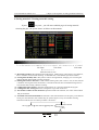
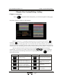
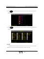
3 Fast setting page
快速设 定
Press
CELERITY SET
Key,It will enter the first Fast setting page, pictures shows as
follows at this monment:
快 速设 定
Press
CELERITY SET
Key again,It will enter the second Fast setting page ,pictures
shows as follows at this monment:
The two pages gather all the common parameters information of the machine,
It includes the important parameters for debugging,such as :open mold ,close mold,
ejecting pressure-keepping ,stuff-storing,and temperature.
R
16
Chapter 3: Descriptions on setting parameters/functions
User's Manual for TB108 V2.0
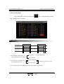
4. Mold open and close setting
Press
开锁模
key,will enter Open /Close mold setting page , picture shows as
M.PLT
follows at this moment.
The parameter established / movement procedure / the function way explaining
shut fast ─── → Low-pressure ── ─→ High pressure ── ─→ Finish locking
High-pressure time
20.0mm
5.0mm
(X 03)
├ ── ── ─ ─→
Low-pressure Protection time 6. 0sec
(1) Close mold: enter the locking mould fast, walk to 20. 0mm , enter low-voltage locking mould ,
walk to 5 .0mm more . Enter high pressure locking mould , wait high-pressure time get to end or X03
input point is ON , then locking moulds have finished . warning [Low-voltagly Protection time have
arrived] when low-voltage time arrive but does not transfer to high pressure yet, and opened the mould
automatically.
(2) low-pressure time limit : low-voltagly Protection time of shutting mold, please don't establish too
big as much as possible , it should be suitable , otherwise the situation of protecting the muld will
not appear.
slow opening ─ ── → fast Opening── ─ →
low opening───→ Finish opening
50.0mm
220.0mm
350.0mm
(3) Open mold :carry throughopen mould unload firstly, the time enter the mould-opening slow speed ,
when walking to 50.0mm ,Switch to turn on mould fast ,when walking to 220 .0mm., Switch to
turning on mould's low-speed , when walking to 350.0mm more ,switch is over. at the.
(4) Open and Close the mold limit time: Show the restriction time to turning on the mold or locking the
mold, please don't establish too small as much as possible , should suitable ,
otherwise systemwill warning [turn on / shut mould not finished timing ].
(5) Manipulator: If need to use the manipulator , please choose [use ], after choosing to use, at the
full-automatic mode, output manipulator signal after machine turn on mold, lock mold enter the
next circulation after ensure received mechanical signa and expire manipulator signal export at the
same time .
R
17
User's Manual for TB108 V2.0
Chapter 3: Descriptions on setting parameters/functions
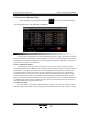
5.Injecting /Blowing setting
Press
射
出
INJECTION
Key,It will enter the Injecting/Blowing setting page,picture
shows as follows:
The parameter established / movement procedure / the function way explaining
One seg ─ ── → two seg─ ── → three seg── ─ → Pressure-keeping
120.00mm
70.00mm
5.00mm
├─────────────→
Total injection time 12.0 0 sec
(1) Movement procedure: After one seg walking to 120.00mm ,it switchs to two seg ,then
To 70.00mm switching to three seg,then to 5.00mm switching to pressure-keeping.
(2)Total Injection time:monitor the normal injecting procedure,it will count when enter
Injecting, until the time is up ,no matter whether it has switched to the pressure-keeping ,
so the total injecting time should be above the actual time.
(3) Inspecting Injection : Can choose [use ]and [no use], when choosing to use under half / fullautomatic mode, The computer fetches shooting the average number value of terminal point
of 20 the first moulds as jetting our check-point automatically, users can establish the allowing
error number value range . If after the 21st mold , find that shoots not reaching this check point
or exceeding this check point , then warning [jetting fail ], management regard this mold as the
bad product in output at the same time .
(4) Blowing state: can choose [no use],[left blowing],[right blowing]and [left and right blowing],
It can use on the mold which need to blowing.
(5) Beginning position: can choose [before mold open] [after mold close] to blow
(6) Delay time: runing to the beginning postion,it will delay firstly.then it will blow when the time
is up.
(7) Inject mode : can choose [time] or [route] ,if choose [time],it means it will terminate after all the
setting time of each seg is up,if choose [route],it is controlled by the route and the total injection
time.
R
18
User's Manual for TB108 V2.0
Chapter 3: Descriptions on setting parameters/functions
6.Storing material / Cleaning materials setting
储 料
If press
FEEDING
key once , you will enter establish pages of storing material /
releasing the glue , the picture shows as follows at this moment:
The parameter established / movement procedure / the function way explaining
F r o n Re l ea se─ ─ ─→m at e ri al───→p os t rel e a s e───→r e ls ased
20.0mm
150.0mm
220.0mm
├ ── ── ─ →
Melt time limit 25.0 sec
(1) Movement procedure: after finished pressure-Protection , walking to 20. 0 mm switch to store material ,
then to 150 0mm. switch to back releasing . To 220.0mm.more . Store material eject back finished
(2) Storing material delay time: delay time in order to storing material, changing over to storing the
material through delayed after pressure pretection.
(3) limiting time of Store material: For lack material warning time ,when reach to time ,if store material
is immature .then regard as lack the material, so the time of the limit time is established longer than to
store material time actually, otherwise warning .
(4) Cooling time before storing: when the cooling time is up ,it will store material and jet gule.
(5) Cooling time after storing: wehen the cooling time is up,it will do the next.
(6) The number of times of clear material: repeated to make clear material , the times of movements
that jet movement.
(7) Automatic clear material method: The automatic clear material function is had [uses ] in the manual
mode, press the automatic clear material key, the system begins to carry out automatic clearing
material movements, the movement procedure is as follows:
seat up
jet out
clear material
pump latter
[no ]
whether number of times
already arrive
[Yes]
Over
R
19
User's Manual for TB108 V2.0
Chapter 3: Descriptions on setting parameters/functions
7.The seat platform / the thimble materials setting
座台/托模
If press
NOZZ/EJE.
key, you will enter a platform / the thimble and set pages, the
picture displays as follows at this moment:
The parameter established / movement procedure / the function way explaining
(1) The seat rises automatically: Can choose [no use] or [finish storing] or [cooling over ]; if
choose [finish storing] after storing material ,make rising movement when operating auto
mati cally; if choose [cooling over ], after finishing, make a rising movement when operating
automatically.
(2) S eat platform e nter delay: While operating auto matically, delay time is up ,and then the sea t
pla tform ente r
(3) Seat platform retreat delay: While operating automatically , delay time is up,and then the
seat platform retreat
(4) Thimble way: Can choose [order] or [stay]; if choose [stay ], then on semi-automatic state,
enter movement reach terminal then stop to carry, make and carry retreating until the next
circulation before imprison mould.
(5) The times of the thimble: Set the times of thimble movement
(6) Thimble enter delay: While operating automatically, delay time after finishing opening the
mould and then carry enter.
(7) Thimble retreat delay : While operating automatically , delay time after finishing carrying
into enter and then carry and retreat again.
(8) [The note ]: while manually , it is not limited by the times (but can't be 0000 ) .
R
20
User's Manual for TB108 V2.0
Chapter 3: Descriptions on setting parameters/functions
8..slippery Mould /orienting material setting
If press
滑 模 /中 子
TABLE/CORE
key , you will enter the page of slippery mould / orienting setting, the
picture displays as follows at this moment:
The parameter established / movement procedure / the function way explaining
(1) Slippery model function: Can press the input key to choose [Not Use ] or [Use ], when choose [Use ].
the set way of slippery model is effectively.
(2) Slippery model way: Can press the input key to choose [slip on the left ], [Slip in right ] or [Pair slips ].
(3) Choose slip on the left: Open mould ---Do left slippery movements ---- Slip on the left ----Thimble
----- Thimble finished ---- Wait ----- Press the left / right shut mould button -----Slip in right ----- finish
Slipping in right -----Shut the mould ----- Begin the second circulation.
(4) Choose slip in right: Open mould ---- Do slippery movements in right ---- Slip in right ----Thimble
---- Thimble finished--- Wait --- Press the left / rignt shut the mould button --- Slip on the left -----finish
Slipping on the left ----Shut the mould ----- Begin the second circulation
(5) Choose pair slip: Open mould ---Wait ---Press the left / right shut the mould button, if the model does
slippery movements in right as above -----Then slippery movements on the left -----finish Slipping on
the left ------Shut the mould -------Begin the second circulation.
(6) Single slide machine : slip out if Slip on the left, slip into if slip in right.
(7) The delay slipping on the left: the time from open the mould to the time of beginning slipping left.
(8) The delay slipping on the right: the time from open the mould to the time of beginning slipping right
R
21
User's Manual for TB108 V2.0
Chapter 3: Descriptions on setting parameters/functions
9 Neutron / entangle tooth setting
滑 模/中 子
If press
TABLE/CORE
key two times, you will enter the page of release core/ entangle tooth
setting , the picture displays as follows at this moment:
The parameter established / the function way explaining
(1) pump core shape: You can choose [stop time ], [stop journey ], [entangle tooth count ], [no use ],
choose [stop time ], set time to stop pumping core movements; choose [stop journey ], stop pumping
core movements when inputting some breaks alarms [ON ]; if choose [entangle tooth count] , you can
control the entangle tooth , stopping determined by the pulse number of inputting entangle tooth.
(2) Initial position: the begin position of Enter Core and Produce Core , namely where stop template ,
the settlement value that pumping core A , B.
(3) The delay of entering the core : delay first after run automatically enter the core B initial position ,
when delay-time end, then make procedure movements of entering core B.
(4) The delay of output Core B: delay first after run automatically enter the core B initial position , When
delay-time end , then make procedure movements of output core B.
R
22
User's Manual for TB108 V2.0
Chapter 3: Descriptions on setting parameters/functions
10 time / count setting
时 间
If press
TIME
key, you will enter time / count setting pages, the picture displays as
follows at this moment:
The parameter setting instruction
(1) Lubricating time: Display that single running time of oil pump.
(2) Lubricate moduluses: calculate the times of opening mould .When the times reach the setting value,
oil pump begin to work.
(3) Middle time: In the full-automatic course, the time is from thimble work finished to the next
circulation lock ,
(4) Movements limited time: The permission longest time that movements are outputted
(5) Cycle time: The limited time of operation cycle in the automatic course, if the time that circulation
operates actually exceeds cycle, the system warn [cycle time is up ].
(6) Warning signal of the trouble: from trouble beginning to the stopping of warning avoid a long time
warning.
R
23
Chapter 3: Descriptions on setting parameters/functions
User's Manual for TB108 V2.0
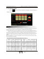
11 The temperature setting
If press
温 度
TEMP.
key, you will enter temperature setting pages, the picture displays as
follows at this moment:
Parameter setting instruction
Temperature setting unit is 0.1 [degrees Centigrade ], vertical machine material tube temperature is
feedback to the ring control of control system by K , J Model electric thermocouple line.
System altogether offer five sections temperature controls and a sections of oil temperature measure.
Dozzle can choose [opening ring] /[closing ring ] control. Except controlling temperature, the system
also controls the temperature of every district, see whether it surmounted the upper and lower limit set,
temperature lower than lower limit can not jet glue and melt glue which hinder cold spiral shell's pole start;
temperature is higher than upper limit then warning .Each section temperature states display in the main
picture .
Screw rod cold start: Each segment real temperature will reach the setting scope first time after machine
start, and will keep the setting time.
Part
tube
for资
reference
部
分plastic
塑 胶density
密 度 and
与 料
管heated
加 热temperature
温 度 参 考
料
Temperature
Te
mperature
Desity
Desity
Name
Name
原料简名
密度
加热温度º CC
原料简名
密度
加热温度º
CC
A.B.S
1.01-1.05
190-270
PMMA
1.17-1.20
180-260
O
O
PS
A.S
1.05
1.06-1.07
190-240
180-250
PPO
PA/NYLON
1.08-1.09
1.08-1.17
260-330
230-290
H.P.S
L.P.S
1.05-1.08
0.91-0.93
220-280
150-260
NYLON66
PVC/S
1.03-1.15
1.20-1.40
280-330
150-180
H.P.E
0.94-0.96
190-260
PVC/H
1.30-1.58
160-200
P.P
0.98-0.90
200-290
P.E.T
1.38-1.41
280-310
P.C
P.O.M
1.2-1.22
1.41-1.42
280-320
190-230
P.T
1.41-1.52
220-280
R
24
User's Manual for TB108 V2.0
Chapter 3: Descriptions on setting parameters/functions
12 Preheat materials setting
If press
温 度
TEMP.
key Two times, you will enter the preheat setting pages, the picture
displays as follows at this moment:
parameter setting instruction
Preheating Function: make an appointment in seven days of one week. This system offers the function
that whether some day use the heating in advance or not. You will not use preheat function by choosing
[OFF ]. If you chose [ON ], the system will control the heating of the heating system, according to the
setting value of turning on / off time in the day. The machine will heat the material tube to working temp
erature automatically before the operator works, reduce the time of waiting for .
*[The note ]: The time inputting value adopts 24 hours.It is expressing 12:00 at night if input 00:00
R
25
User's Manual for TB108 V2.0
Chapter 3: Descriptions on setting parameters/functions
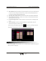
13.The mould materials establishing
资 料
Press
DATUM
key, will enter the mould materials establishing pages, the picture
shows as follows at this moment:
The parameter establishing explaining
(1) Mould serial number: This control system can store 80 groups of mould symbols , after altering the
mould serial number, the system output the materials of symbol of the mould automatically.
(2) The mould stores method: Cursor move to the mould serial number colume , import the numberl of
the mould , and then move the cursor to the mould name column, after input the mould name, move
cursor to store column.press the store key to store. this system offer inputting way in English and
spelling.
(3) The mould fetches method: in mould serial number fence , input mould number which will be read ,
move the cursor to ourput column and press the import key to read .this will change the number ar
present and the whole page materials . For prevent from in half / full-automatic mode, page establish
sudden change of parameter will cause harmful effects to product quality and cause contingency
acciden , the mould fetches function is only limited to the manual mode.
(4) Delete method: move the cursor to mould serial number fence , input mould number which will
bedeleted , then import import key to delete in delete fence . the present mould can't be deleted.
(5) the Method that refer the mould: move the cursor to the scanning fenceand utilize upper and lower
key move the picture refer .
R
26
User's Manual for TB108 V2.0
Chapter 3: Descriptions on setting parameters/functions
14. Data modification record
Press
资 料
DATUM
Key twice ,It will enter the data modification record page ,
picture shows as follows at this moment:
Parameters setting explaining
(1) print list :open the print list of the printer.
R
27
User's Manual for TB108 V2.0
Chapter 3: Descriptions on setting parameters/functions
15. Special parameters setting
Press
1
STU
k ey, you will enter the special parameter adjusting / establishing pages,
the pictur e shows as follows at this moment:
( 1) Modify the password: move the curso to the “assword modification”. Press
输 入 key ,I t will enter the password modificaion page .
ENTER
R
28
User's Manual for TB108 V2.0
Chapter 3: Descriptions on setting parameters/functions
(2 ) Move the cursor to the [system language] button , then press 输 入
ENTER
key ,a new page will popup,picture shows as follows:
( 3) System menu: Move the cursor to the [System menu],then press 输 入
ENTER
key ,It will enter into the system menu page:
R
29
User's Manual for TB108 V2.0
Chapter 3: Descriptions on setting parameters/functions
(3a) LCD Contrast adjusting: It means adjust the brightness ratio, at a certain brightness ,The contrst
is greater ,the color is more plentiful. Adjust scope (0-100%) [note :This is only for STN screen]
(3b) LCD brightness adusting: move the cursor to there ,enter the number [adjusting scope (0-100%)],
the brightness of the screen will changed according to the input number.
(3c) LCD color setting :The system offer [the normal, against color ] two kinds of choice, move cursor
to that ,then prss [enter] key to exchange each other ,
(3d) LCD background light time setting : The system possesses the screen protection function,
background light time can be established, establish the range for 1- 6 minutes, if establishing has
not operated the keybo ard in timing, then the background light automatic OFF.
(3e) keyvoice : The system offer [use/nouse] two choice,move the cursor to that ,then press [enter] key to
exchange each other.
(3f) keyvoice up and down : move the cursor to that ,input number [scope (0-10)grade], the volume
will changed according to the input number
(3g) IP address modification: Set the IP address when you use network,move cursor to that then prss
[enter] key the IP address will changed sucessfully
(3h) State of the network:display the state of the network by color
(3i) Current IP: display the IP of the machine
(3j) Current connected state :display the connected state of the network :disconnected/connected.
R
30
Chapter 4: Product Management
User's Manual for TB108 V2.0
Chapter four: Product Management
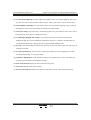
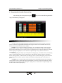
1、Product data setting
生产 管理
Press
FLOW CHART
key once, you will enter production materials establishing pages, the
picture shows as follows at this moment:
The parameter establishing explaining
(1) Good product: the good product is equal to the moduluses has already been made multiply by the
quantity of a mould and deduct the bad . The bad product is controlled by the function of shotting and
measure ,when jetting measuring is in use, n the course , if excessive or insufficient state taking place ,
bad product increase one mould quantity value, and warning [measure to the bad product ].
(2) Establishing moduluses: establishing produce Modulus in advance, system automatic reach the frirst
5 moulds of already opening modulus established, the alarming until the modulus arrives.
(3) Shut down warning : Can choose [use ] , [not need ], after establishing moduluses reaching if
choosing no, machine continued producing, did not shut down until after the operator shuts down.
(4) Method that the production record refer: move the cursor to production record fence and utilize
upper and lower key to look out .
R
31
Chapter 4: Product Management
User's Manual for TB108 V2.0
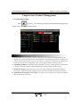
2、SPC tracing record
生产 管理
Press
FLOW CHART
key twice, you will enter SPC tracing record page , the picture shows
as follows at this moment:
The parameter establishing explaining
(1) Pages: 999 modulus continual data in tota,The SPC tracing record offers 6 important parameters of
latest 999 modulus for production management. Let the operator know better the changes of real
tested parameters in every production cycle,and adjust corresponding changes.and then increase the
quanlity of the product.
(2) Print lis: start the print list of the printer
R
32
Chapter 4: Product Management
User's Manual for TB108 V2.0
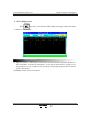
3 Pressure-speed curve
曲 线
Press
key once ,It will enter into the Pressure -speed curve page ,picture
CURVE
shows as follows at this monment:
The parameter establishing explaining
(1) Choose display: Choose the curve you what to display ,can choose [ejection speed],[pressure keeping ]
[mold close pressure], pressing enter key is ok.
R
33
Chapter 4: Product Management
User's Manual for TB108 V2.0
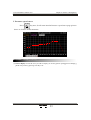
3 Temperature tracing curve page
曲 线
Press
key twice ,It will enter into the temperature tracing curve page ,
CURVE
picture shows as follows at this monment:
The parameter establishing explaining
(1) Choose display: that is ,choose which segment to display its tracing record curve.this function offers
parameters about 6 hr in advance of 6 segments ,temperature.Let the operator know better the
changes of the real temperature, compare and analyse the influence on the quanlity of the product.
(2) The interval of sampling record: that is ,the interval time of sampling record is 5minutes.
R
34
Chapter 4: Product Management
User's Manual for TB108 V2.0
5. Warning record page
诊 断
Press
key once ,it will enter the warning record page ,piture shows as
DIAGNOSE
follows at this monment:
参parameter
数 设定??
The
establishing explaining
(1 ) Lists:The system offers 999 warnings for inquery at most ,gives maintenance more
convenience.
( 2 ) Print lists:start the print list of the printer.
R
35
Chapter 4: Product Management
User's Manual for TB108 V2.0
6. USB setting page
PC连接
P re ss
Key once,It will enter USB setting page ,picture shows as follows
PC LINK
at this monment:
The
establishing explaining
参parameter
数 设定??
(1) Data download: That ,s ,download mold data to usb
(2) Materials upload : upload mold materials to system from usb
(3) System material download : download system material to usb
(4) System material upload: upload material to system from usb
(5) Begin/End D: setting data scope when download materials
(6) program the main machine : update main machine ,press stop key first
and then move the cursor to [program],press enter key,.move the cursor
to the [.hex] file which is you want to update
(7) update OPWIN.PS6 : update program of the keyboard ,move cursor to
[update],press enter key and then move the cursor to the file [.PS6] you
want to update
(8) update start file: update the start page ,move cursor to [update],press enter
key ,and then move the cursor to the file [.bmp] you want to update
R
36
Chapter 5 System Debug Setting
User's Manual for TB108 V2.0
Chapter five: System Debug Setting
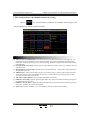
1.Engineer setting page
Press
0
Key,button In the main picture, you will enter engineer's setting page,
the picture displays as follows at this moment:
Input the password * * **And then if the password is correct th en your can enter
if incorre ct
, you can enter until the correct p assword is entered. Then you can en ter the
systematic parameter setting pages after. If you are the end user of the machine, you need not to
adju st the systematic para meter please contact supplier if there is doubt, otherwise the parameter
is adjusted messily, may damage the performan ce of the lathe and cause unstable or unable to run.
After the password is input correctly, the cursor will jump to the first column on the right
automatically , can choose every column content again with the
key ,press, the buttonto
enter. Or press buttons the following and enter the corresponding page directly:
press. The
输 入
button enters the page.
ENTER
Key
开锁模
M.PLT
射 出
INJECTION
储 料
FEEDING
座台/托模
NOZZ/EJE.
Key
Entering Page
滑模/中子
<Delay Setting>
TABLE /CORE
时 间
<Pressure/Flow Setting I>
TIME
<Pressure/Flow Setting II>
<Pressure Pre-Adjustment>
<Flow Pre-Adjustment>
<Back Pressure Adjustment>
温 度
TEMP.
资 料
<Electronic Ruler Setting>
DATUM
R
37
Entering Page
<Special Function Options>
<Standby Function Setting>
<Programmable Standby
Points>
<Temperature Parameter/
Time Setting>
<Machine No./Ex-Factory
Value Setting>
Chapter 5 System Debug Setting
User's Manual for TB108 V2.0
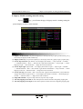
2. Delay Setting Page
开锁模
After entering the correct password, press
M.PLT
Key to enter the Delay Setting
Page. The following is displayed:
Description on setting parameters
Action Valve
Pressure Valve
Flow Valve
T1
(1) The meaning of Start Delay: the
corresponding action valve ON →
(2) The meaning of End Delay: the
→
corresponding action valve
T2
T1
T2
delay time T1 → pressure output ON
flow output ON
pressure output OFF
→ delay time T2? action valve OFF
flow output OFF
(3) The setting ranges for the Start [T1] and the End [T2] are 0.0-0.5 seconds.
R
38
Chapter 5 System Debug Setting
User's Manual for TB108 V2.0
3. Pressure/Flow Slope Setting Page
After entering the correct password, press
射 出
INJECTION
Key once to enter Pressure/Flow
Slope Page I. The following is displayed:
射 出
After entering the correct password, press
INJECTION
Key twice to enter Pressure/Flow Slope
Page II. The following is displayed:
Description on setting parameters
The Pressure/Flow Slope refers to the steep degree of rise or fall when the pressure/flow changes
from one value to the next value.“1” stands for the slowest change and “16” stands for the fastest
change. The setting range is [1-16].
R
39
Chapter 5 System Debug Setting
User's Manual for TB108 V2.0
4. Pressure Pre-Adjustment Page
After entering the correct password, press
储 料
FEEDING
Key once to enter the Pressure
Pre-Adjustment Page. The following is displayed:
Description on setting parameters
The pressure pre-adjustment is the linear adjustment of pressure output. In general, the standard
pressure is 0-800mA and the standard output impedance is 10-20 Ω,unless the manufacturer has specific
requirements since different manufactures' overall oil piping designs and the capabilities of the pressure
proportional valve being used are different.
Pressure Adjustment Method:
The parameters on this page have been set before ex-factory. If the capability of the proportional
valves being used by the user is different, and the normal proportion and linear proportion cannot be achieved,
the parameters on this page can be adjusted. First set the pre-adjustment to be [Activated], and then set the
pre-adjustment item to be [ON]. For example, for the 50 bar pressure position of Item 50, if the reading on
the pressure meter is 45 bar, the parameter of this item should be increased until the pressuremeter reading
reaches 50 bar. Make adjustments on all parameters which need adjusting and make the0-140 bar pressures
being set correspond to the pressures being shown on the oil pressure meter respectively.After the adjustments
are completed, the computer executes automatically linear processing and takes theprocessing results as the
subsequent normal D/A proportional output values.
Press linear pre-adjust:
Enter the number in the 160bar pre-adjustment firstly , then move the cursor to the [pressure linear pr
e-adjust], and press the enter key to choose [on],The system will allocate the data to 10bar -160bar on average.
R
40
Chapter 5 System Debug Setting
User's Manual for TB108 V2.0
5. Flow Pre-Adjustment Page
After entering the correct password, press
储 料
Key twice to enter the Flow Pre-
FEEDING
Adjustment Page. The following is displayed:
Description on setting parameters
The flow pre-adjustment is the linear adjustment of flow output. In general, the standard value
is 0-800mA and the output impedance is 40 Ω,unless the manufacturer has specific requirements since
different manufactures' overall oil piping designs and the capabilities of the pressure proportional valve
being used are different.
Flow Adjustment Method:
The parameters on this page have been set before ex-factory. If the capability of the proportional valves
being used by the user is different, and the normal proportion and linear proportion cannot be achieved, the
parameters on this page can be adjusted. As for the speed adjustment, different manufacturershave different
measuring methods. Some manufacturers use the melt tachometer to measure the rotation speed. First heat
the barrel until the barrel temperature reaches normal melt temperature. Set the melt speed to be 1, 10, 20, 30,
and more until 99 and check the actual values. Make adjustments on all parameters whichneed adjusting and
make the 0-99% speeds being set correspond to the proportional coefficients being shown on the tachometer
respectively. After the adjustments are completed, the computer executes automatically linear processing and
takes the processing results as the subsequent normal D/A proportional outputvalues.
Flow linear pre-adjust :
Enter the number in the 99% Flow pre-adjust,then move the cursor to [Flow linear pre-adjust],and press
the enter key to choose [on],The system will allocate the data to 10%-90% on average.
R
41
Chapter 5 System Debug Setting
User's Manual for TB108 V2.0
6. Back Pressure Pre-Adjustment Page
After entering the correct password, press
储 料
FEEDING
Key three time to enter the Back
Pressure Pre-Adjustment Page. The following is displayed:
Description on setting parameters
The back pressure pre-adjustment is the linear adjustment of back pressure output. In general, the
standard pressure is 0-800mA and the standard output impedance is 10-20 Ω,unless the manufacturer has
specific requirements since different manufactures' overall oil piping designs and the capabilities of the
pressure proportional valve being used are different.
Back Pressure Adjustment Method:
The parameters on this page have been set before ex-factory. If the capability of the proportional
valves being used by the user is different, and the normal proportion and linear proportion cannot be
achieved, the parameters on this page can be adjusted. First heat the barrel until the barrel temperature
reaches normal melt temperature. Set the melt back pressure to be 1, 10, 20, 30, and more until 160 and
check the actual values. Make adjustments on all parameters which need adjusting and make the 0-160
bar back pressures being set correspond to the back pressures being shown on the back pressure meter
respectively. After the adjustments are completed, the computer executes automatically linear processing
and takes the processing results as the subsequent normal D/A proportional output values.
Back pressure pre-adjust:
Enter the number in the 160bar pre-adjust,then move the cursor to [back pressure linear pre-adjust],
and press the enter key to choose [on],the system will allocate the data to 10bar -160bar on average.
R
42
Chapter 5 System Debug Setting
User's Manual for TB108 V2.0
7. Electronic Ruler /Pressure Inspection Setting Page
After entering the correct password, press
座台/托模
NOZZ/ADJ.
Key once /twice to enter the
Electronic Ruler/Pressure Inspection Setting Page. The following is displayed:
Description on setting parameters
(1) Electronic Ruler Function: If the equipment needs to use the electronic ruler, choose [Activated]. If the
equipment adopts stroke switch control, choose [Deactivated].
(2) Measurement Values: indicating the actual dynamic positions of the electronic rulers for the clamping
unit, the injection unit and the ejector.
(3) Total Length: referring to the actual lengths of the electronic rulers for the clamping unit, the injection
unit and the ejector.
(4) Limit Position: It refers to the maximum value set for the position. This parameter is subject to the
maximum position setting. For example, if the parameter set is bigger than the limit position value, the
system will not accept the parameter set and will retain the original setting.
(5) Zeroing: When the equipment choose [Activated] for the Electronic Ruler Function and uses the
electronic ruler, it may appear that the mechanic movement stroke is in place and yet the actual
positions of the electronic rulers for the clamping unit, the injection unit and the ejector do not indicate
“0”. In such case, the corresponding ruler should be zeroed. Move the cursor to the zeroing button
for [clamping unit ruler], [injection unit ruler] and [ejector ruler], and then press
输 入
ENTER
zero clearing for the corresponding electronic ruler.
(6) Sensor: The method of setting is similar to the elcetornic ruler.
R
43
Key to make
Chapter 5 System Debug Setting
User's Manual for TB108 V2.0
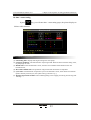
8.Special function setting page
After password input correctly, press
滑 模/中 子
TABLE /CORE
the button, you will enter and
delay setting pages, display as follows:
The parameter setting instruction
(1) The ways of thimble stop: Choose the journey and the set will be stop by journey. Choose time and
the set will be stopped by time .
(2) Open mold while storing stuff: Open mold when the cooling time is up ,Needn ,t wait for stroing
stuff end.
(3) The ways of platform retreat: Choose the journey and the set will be stop by journey. Choose time
and the set will be stopped by time .
(4) storing material key locked by itself: when use ,press the key once ,and it will store material continually
until the time or the position of storing materail is up. Or press the key again to end this action.
(5) The motor dallies and stops by oneself : the limited time set ed is effectively that the motor dally while
using.
(6) The motor racing limit time: Set range is 2-999 min, when starting, system measure is in this time, the
machine closes the motor automatically when not doing any operation, in order to protect the life-span
of motor and save the electric rate.
(7) Shut mould self-insurance : [quick][low pres]Can choose fast[quick ] , low-voltage , begin self-insurance
while choosing fast; Begin self-insurance while choosing [low-voltage ] low-voltage .
(8) Shut mould stopping : [While choosing time to the high pressure of shutting mould, high-pressure
time begins to time, time to shutting the mould to stop promptly; Choose journey and end point of
shutting mould is on ,then shutting mould promptly stop.
(9) Shut mould fast: Y51 chooses guide valve to export all the time while opening themould; Choose
differential Y51 and not export while opening the mould.
(10) The slippery mould is used : Can choose pairs of slippery mould , single slipperymould , no need, this
fence function choose will decided is by display of page and using choose of slippery mould function.
(11) Full-automatic : While choosing to use, the machine can run full-automatically.
R
44
Chapter 5 System Debug Setting
User's Manual for TB108 V2.0
( 1 2 ) full-automatic test: the machine will run automaticlly cycle by cycle.this function
,
is only for test and debug in machine factory.it don t use in normal production.it
is in nouse by default when the machine start.
( 1 3 ) Ejecting while clos ing mold:this function only works when double silding mold.
( 1 4 ) Open mol d and download: can choose use or nouse,it will download firsly ,then
open mold slowly when it use.
( 1 5 ) location/entan gle tooth:can choose all nouse or location in use or entangle tooth
in use.
( 1 6 ) Ty pe of machine: can choose common machine or C type machine ,this will
determine the display in monitor page.
After entering the engineer page , press
滑 模/中子
TABLE /CORE
key twice ,it will enter into the
proportion limit page,picture shows as follows at this monment:
The
parameter
setting instruction
功能
参数设定??
( 1) Pre ss /F low up limit : these parameters value will determine the up limit in all pages in
mold parameter setting page .
R
45
Chapter 5 System Debug Setting
User's Manual for TB108 V2.0
9. I/O Transfer Setting Page
After entering the correct password, press
时 间
TIME
Key to enter the Standby Function
Setting Page. The following is displayed:
Descriptions on setting parameters function mode
(1) Output Point Transfer Function: This function can be activated or deactivated. If activated, the output
point executes immediately transfer operation. In case that mal-function or damage occurs to a certain
point, the control can be transferred to another point by activating this function. For example, in case
that failure occurs to the mould opening output point and the knockout core function is deactivated, the
Y46 mould opening point can be transferred to Y66 and then the output wires should be exchanged.
The system is equipped with the function of simultaneously transferring two output points. Once this
function is activated, the system makes judgment on the two selected items. If the item is [ON], the
transfer of the pre-set conditions of the item will be executed.
(2) Input Point Transfer Function: This function can be activated or deactivated. If activated, the input
point executes immediately transfer operation. In case that mal-function or damage occurs to a certain
point, the control can be transferred to another point by activating this function. For example, in case
that failure occurs to the front safety door input point and the knockout core function is deactivated,
the X00 front safety door input point can be transferred to X25 and then the input wires should be
exchanged. The system is equipped with the function of simultaneously transferring two input points.
Once this function is activated, the system makes judgment on the two selected items. If the item is
[ON], the transfer of the pre-set conditions of the item will be executed.
R
46
Chapter 5 System Debug Setting
User's Manual for TB108 V2.0
10. Programmable Standby Function Page
时 间
After entering the correct password, press
TIME
Key twice to enter the Programmable
Page. The following is displayed:
Descriptions on setting parameters function mode
In order to meet diversified application needs and provide an innovative product, we take the
initiative to offer the programmable standby function page so that the users can define and revise by
themselves the functions and the action sequence.
Example 1: For a certain mould injection machine, due to the different design of the oil piping, it
is required that a point is output while clamping at high pressure and the power will not be interrupted
until the melt finishes taking out. To achieve such a special function, choose an item and have it activated,
and then specify an output point (i.e. this function is output through Y xx), and then set the action
sequence [CD].
Notes: Regarding the output scope of Sequence D Clamping Stop, in automatic mode, the clamping
switch is contacted during the process of mould close at high pressure, and this sequence output starts
until the melting finishes; in manual mode, the clamping switch is contacted during the process of mould
close at high pressure, and this sequence output starts until the mould opening key or the reset key is
pressed.
Example 2: For a certain mould injection machine, due to the different design of the oil piping, it
is required that a point is output while injecting and melting. To achieve such a special function, choose
an item and have it activated, and then specify an output point (i.e. this function is output through Y xx),
and then set the action sequence [FH].
R
47
Chapter 5 System Debug Setting
User's Manual for TB108 V2.0
11. Temperature Parameter/Time Setting Page
After entering the correct password, press
温 度
Key to enter the Temperature
TEMP.
Parameter/Time Setting Page. The following is displayed:
Descriptions on setting parameters function mode
(1) Nozzle ,Seg I ,Seg II ,Seg III ,Seg IV,Seg V : [use] and [nouse] can be chose ,if [nouse],the syestem
will not inspect and control on this segment.
(2) Oil Temperature Selected: [Activated] or [Deactivated] can be chosen. If deactivated, once it is
detected that the oil temperature is equal to or over the set upper limit, the alarm will be neglected.
If activated, the alarm will be output, and the system will turn to manual mode and the motor will be
turned off when the alarm cycle ends.
(3) Pd Setting: Pd has been set before ex-factory. It is recommended that the user should not revise this
parameter under normal circumstance.
(4) Proportion Setting : proportion control is a simplest control way ,the output of the cotroller is
proportionate to the input inaccuracy signal. There will be stable inaccuracy in output only with
proportion controller.
(5) Differentiation control: In differentiation control, the output is directly proportional to the input signal
error differentiation the auto control system maybe vibrate or even instable in the process of overcoming
error.because the existed large inertia component and the lag component can inhibit the error. its change
is always lose behind the change of the error .the solution is to make the change of the inhibition error
in advance .that is when the error is close to zero ,the inhibition error should be zero.so ,the "proporiton"
item is not enough in the controller , the role of "proportion" is only to enlarge the error.we should add the
"differentiation"which can predict the tendency of the error. thus ,with proportion and differentiation ,the
controller will be able to make the role of inhibition error to zero or even negative in advance .and avoid
overadjust of the controller. Therefore, greater Inertia or lag charged object, the proportion of + differential
(PD) controller can improve the system dynamic properties in regulating.
R
48
Chapter 5 System Debug Setting
User's Manual for TB108 V2.0
12. Machine No./Ex-Factory Value Setting Page
After entering the correct password, press
资 料
DATUM
Key to enter the Machine No./Ex-
Factory Value Setting Page. The following is displayed:
Descriptions on setting parameters function mode
(1) Mould Injection Machine No.: The system is equipped with the function of setting NO. for the mould
injection machine so that the manufacturer can set the No. for easy sales management and after-sales
service record.
(2) Ex-Factory Value Restoration: During the modifying process of password pages, if normal operation
cannot be achieved due to too much deviations of the modified parameters, press Key Enter and
choose Confirm, and then all the contents and all the parameters will be restored to the standards valu
es set before ex-factory.
R
49
Chapter 6 Input/Output Mode Inspection
User's Manual for TB108 V2.0
Chapter 6 Input/Output Mode Inspection
1. Input Inspection Page
(1) Press
2
VWX
Key on the Main Page to enter Input Inspection Page and the following will be
displayed:
(2) Press
3
YZ
Keyon the Main Page to enter Input Inspection Page I and the following will be
displayed:
R
50
Chapter 6 Input/Output Mode Inspection
User's Manual for TB108 V2.0
(3) Press
3
YZ
Key on the Main Page to enter Key Inspection Page I and the following will be
displayed:
(4) Press
4
JKL
Key on the Main Page to enter Key Inspection Page II and the following will be
displayed:
NOTE:
The above input inspection pages are used for signal inspection and cannot accept information
modified. The solid box on the display indicates that the signals are being input.
R
51
Reference & Appendices
User's Manual for TB108 V2.0
210
194
178
7
34
17.8
228
392
456
470
228
6-M4X12 screw
4
7
7
T B 1 0 8
键盘安装尺 寸图
TB 108 Keyboard Installation Size Diagram
R
52
Reference & Appendices
User's Manual for TB108 V2.0
230
216
194
7
48
42
24.5
135
24
228
456
470
247
228
20
196
6-M4X12 screw
4
7
7
T C 1 0 8
键盘安装尺寸 图
TC 108 Keyboard Installation Size Diagram
R
53
Reference & Appendices
User's Manual for TB108 V2.0
135
PW600 POWER SUPPLY
143
151
7.5
34
15
126
7.5
15
35
Figure of开Dimensions
&尺Installation
Hole
关电源盒 外形
寸及安 装孔位
图 Positions
for Power Supply Case
8
5
170
190
P S660B M
180
151
220
34.5
5
6
8
210
190
19 8
PS8 60 BM
35.75
202
228.5
300
35.75
主机
形 尺 寸 及 安Hole
装孔位
图
Figure of Dimensions
&外
Installation
Positions
for Master Machine
R
54
55
R
P
10VG
S
CGN D
CA H
CA L
GND
+24V
+5V
GND
+ 2 4V
GND
+ 2 4V
2 4 VG
+ 3 8V
3 8 VG
Aj2
Aj1
User's Manual for TB108 V2.0
Reference & Appendices
Reference & Appendices
User's Manual for TB108 V2.0
Motor Electric-Heating connection Diagram
R
56
Reference & Appendices
User's Manual for TB108 V2.0
R S T
3 POWER MCB
Absorption
Component
N
MC1
Absorption
Component
Coil Interference Absorption
N
Contact Interference Absorption
O.L
Absorption
Component
Motor End Interference Absorption
MOTOR
Common Interference Suppression Method (for reference only)
R
57