1
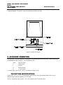
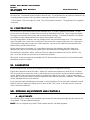
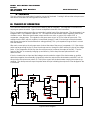
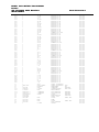
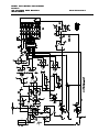
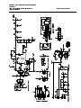
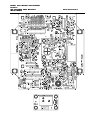
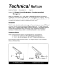
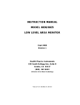
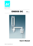
INSTRUCTION MANUAL
MODEL 6031
ION CHAMBER PULSE LINK
AREA MONITOR
March 1998
Version 2A
Health Physics Instruments
330 South Kellogg Ave, Suite D
Goleta, CA 93117
(805) 967967- 8422
Division of Far West Technology
MODEL 6031 INSTRUCTION MANUAL
PAGE 1
ION CHAMBER AREA MONITOR
INSTRUMENTS
HEALTH PHYSICS
INTRODUCTION
The model 6031 is an ion chamber area monitor. It is designed to be powered by an HPI Pulse link Receiver.
The 6031 produces a calibrated pulse output. The instrument will operate over a wide range of doserates and
a wide range of energies.
II. DESCRIPTION AND CONTROLS
The model 6031 has all of the controls and connections on one side (see Figure 1). These include:
Digital Counter: This is a 6 digit up counter that counts up with every pulse that is transmitted on the Pulse
Link.
Counter Reset: Reset for the Digital Counter.
Pulse Link Connection: This is a BNC connector that should be connected to the input to a Pulse Link
Receiver through coax. Both power and data are transmitted on this connection.
Accessory Connector: This connector contains signals for testing the instrument. The connections are
detailed below.
III. INSTALLATION
The model 6031 is installed by plugging it into a Pulse Link Receiver. The BNC on the panel of the 6031
should be mated to the input on the Pulse Link Receiver through a patch cord with a BNC on each end. The
counter should be reset after turn on to make it count properly.
IV. OPERATION
The instrument will produce a pulse rate proportional to the radiation level. 1 mR/h equals .25 Hz and 1 R/h
equals 250 Hz. The instrument will need about 1 minute after turn-on to be operational. Right after turn on
there is about a 10 second delay. Then the instrument produces many pulses per second, tapering off to the
radiation field. This is the high voltage stabilizing. It gives you an indication that the instrument is
functioning.
MODEL 6031 INSTRUCTION MANUAL
PAGE 2
ION CHAMBER AREA MONITOR
INSTRUMENTS
HEALTH PHYSICS
The outer equilibrium wall can be removed for low energy operation. The inner wall is made of styrofoam and
is easily damaged. The sticker on the front indicates the front of the wall
Figure 1 Location of Controls
V. ACCESSORY CONNECTION
CONNECTION
The accessory connection allows the instrument to be operated without the Pulse Link. Some of the signals
are available from this connector. The pin definitions are:
PIN #
DESCRIPTION
K
Output pulse
L
Ground
M
External power
N
+5 VDC output
Connector type: Cannon KPT, 15 pin. Part Number KPT06J14-15P
PIN FUNCTIONS AND DESCRIPTIONS:
Output pulse: This is an LSTTL positive going output pulse for each discriminated event. This is not a
buffered signal, however it will drive 1 LSTTL load.
Ground: Signal and power ground. This is the negative input for external power.
MODEL 6031 INSTRUCTION MANUAL
PAGE 3
ION CHAMBER AREA MONITOR
INSTRUMENTS
HEALTH PHYSICS
External Power: This is the positive input for external power. It can power the instrument instead of or with
the Pulse Link. The external power should be above 9 volts. The instrument can be powered continuously by
connecting external power to this input before removing the Pulse Link connection.
+5 VDC Output: This is an output of 5 volts. This is the positive connection. The ground pin is the negative
connection.
VI. CONSTRUCTION
The electronics is all housed inside the cast aluminum case. The case is gasketed and sealed. To gain
access to the circuit boards, remove the four screws on the bottom of the case. These screws are captive.
The large circuit board is held in place with 4 screws around the edge. To remove the board it is necessary
to unsolder the high voltage lead and unscrew the electrometer connection.
The high voltage lead is located in the high voltage section near the electrometer cover. The electrometer
cover is located in the center of the circuit board. Remove the four screws holding the cover. Remove the
4-40 nut/spacer that holds the lug to the center electrode. Disconnect the cables from the board and the
board is free to be lifted from the box.
Before removing the circuit board, it is a good idea to short the high voltage to ground to keep from
destroying any part of the instrument by getting your hand between high voltage and any component.
The desiccant is mounted in the lid. Make sure that it is replaced or baked out for 3 hours at 300°F if it is
pink. It can also be put in a vacuum oven to remove the moisture.
All controls, screws and openings are treated with RTV silicone sealant to keep the box from breathing with
atmospheric pressure changes.
VII. CALIBRATION
If the instrument is new, perform all the adjustments described in the adjustment section.
Expose the instrument to about 100 mR/h. Adjust R37 until the output frequency reads 25.0 Hz. To adjust
R37 it is necessary to remove the screw on the outside of the case and use a long screwdriver to adjust the
control. Replace the screw and nylon washer to maintain the integrity of the case. It may be necessary to
remove the cover the first time the control is adjusted to learn where to move the screwdriver. The instrument
can be calibrated with the cover removed.
It is a good idea when calibrating the instrument to check the desiccant. The desiccant is mounted in the lid.
Make sure that it is replaced or baked out for 3 hours at 300 °F if it is pink. It can also be put in a vacuum
oven to remove the moisture.
VIII. INTERNAL ADJUST
ADJUSTMENTS
MENTS AND CONTROLS
A. ADJUSTMENTS
The calibration, high voltage, lower threshold, upper threshold, and reset pulse height are all located on the
circuit board. They are adjusted as follows:
NOTE: There is a testpoint for ground TPGND located near the 3 terminal regulators.
MODEL 6031 INSTRUCTION MANUAL
PAGE 4
ION CHAMBER AREA MONITOR
INSTRUMENTS
HEALTH PHYSICS
High Voltage
Connect a high voltage voltmeter probe (>10000 Meg) between TP10 (+ lead) and ground (- lead). Adjust
R75 until the voltmeter reads 700 volts.
Lower Threshold
Connect a voltmeter between ground (- lead) and pin 7 of U1, an LP339 (+lead). Adjust R37 until the
voltmeter reads 0.1 volts. To adjust R37 it is necessary to remove the screw on the outside of the case and
use a long screwdriver to reach the control. Replace the screw and nylon washer to maintain the integrity of
the case.
Upper Threshold
Connect a voltmeter between ground (- lead) and pin 9 of U1, an LP339 (+lead). Adjust R48 until the
voltmeter reads 0.5 volts.
Reset Pulse Height Method 1
Connect the positive lead of a 0.05 volt negative power supply to the chassis of the 6031. Hook the negative
lead to the center terminal of the ion chamber inside of the small electrometer box on the circuit board.
Connect an oscilloscope between ground and the testpoint TP3. Set the oscilloscope on 0.2 V/cm and 10 ms
sweep speed.
Turn R62 20 turns counter-clockwise or until it clicks. Slowly turn it clockwise. At some point you should see
a ramp.. Adjust R62 until the negative portion of the ramp is at .1 volt. The ramp should start at .1 volts and
go to .5 volts. If you turn it too far, there will be large negative or positive excursions.
Reset Pulse Height Method 2
This method should be used as a last resort. It is much touchier and not as easy to set as method 1.
Connect a clip lead from TP 15 to one side of a 1K ohm resistor. With the other side of the resistor touch pin
18 of U3, the 24 pin IC. Push the reset button and wait 2 seconds then remove the resistor. This puts the
instrument in a special mode where it will continually reset itself.
Connect an oscilloscope between ground and the testpoint TP3. Set the oscilloscope on 0.2 V/cm and 10 ms
sweep speed. You should see a negative ramp. Adjust R62 until the period of the ramp is 50 ms.
The instrument will also ramp at turn on. This allows you to check the reset pulse height setting without
connecting the clip lead. Just turn the instrument on and look at TP3. If you do it by turning on the power,
you will also have a rising high voltage and this will effect the reading. If, however you wait a minute or so for
high voltage to stabilize, then push the reset button on the circuit board (S1) then the microprocessor will
initiate a turn on and ramp the system. You only have a few seconds to watch the signal, but you can reset it
as many times as you need. Incidentally there is a delay of a few seconds from the time you push the reset
button until the ramp begins.
CHECKING THE RANGE OF THE DAC
You can also check the DAC at turn on. It ramps up from ground. The signal can be found by looking with
an oscilloscope at pin 3 of U5. The buffered signal is on pin 1, and an inverted signal is on pin 7. The
buffered signal will not go fully positive, and the inverted signal will not go fully negative.
MODEL 6031 INSTRUCTION MANUAL
PAGE 5
ION CHAMBER AREA MONITOR
INSTRUMENTS
HEALTH PHYSICS
B. CONTROLS
The only control is the reset button located on one end of the board. Pushing it will reset the microprocessor
and has the same effect as turning power off and back on.
IX. THEORY OF OPERATION
OPERATION
The instrument measures the current from the detector with an integrator. The integrator is reset when its
output goes past a threshold. Figure 2 shows a simplified schematic of the instrument.
The ion chamber produces a positive current at the inverting input of the electrometer. The electrometer is an
integrator with a 1 pF feedback capacitor, C3. The output of the electrometer ramps negatively from the ion
chamber current. When the electrometer output reaches zero volts, or ground, the output of U2, a
comparator, changes state. This signals the microprocessor to turn on S1 for a few microseconds. The
voltage from the DAC, which is negative, is transferred through C2 and D1 to the input of the electrometer
and causes the output of the electrometer to swing positively. This cycle repeats as long as there is current
from the detector.
After each current pulse, the microprocessor looks at the state of the second comparator, U3. If the charge
pulse was large enough to trip U3, then the microprocessor, through the DAC reduces the size of the charge
pulse. If the comparator did not trip, then the microprocessor increases the output of the DAC. Thus the
output of the DAC is constantly changing up and down by 1 bit to keep the reset pulse at the 0.1 volt
reference level.
If the ion chamber has no input and the leakage currents make the output of the electrometer go positive
rather than negative, then eventually U4 would trip when the output of the electrometer reached 0.5 volt. At
this point the microprocessor pulses S2. This injects current into the electrometer causing the output to go
negative. The microprocessor stops the pulses when U3 trips indicating the output of U1 has dropped to the
0.1 volt level.
Figure 2 Block Diagram
MODEL 6031 INSTRUCTION MANUAL
PAGE 6
ION CHAMBER AREA MONITOR
INSTRUMENTS
HEALTH PHYSICS
When the instrument is first turned on the system ramps up and down using S1 and S2 to set the DAC so that
the current pulse is of the correct magnitude.
The Calibration control changes the level of the 0.1 volt reference and then directly changes the charge per
pulse. 0.1 volt with 1 pF feedback capacitor is 0.1 picocoulombs or 0.1 picoamp for a pulse per second. The
leakage currents are about 1 pulse every minute or about 2 femtoamps. C1 and R1 form an RC network to
smooth out pulsed radiation.
X. CIRCUITRY
Many of the components on the schematic are not used in this model.
The ion chamber generates a positive current. The RC filter R22 and C6 are used to filter out fast peaks and
smooth the signal going into the digitizer. U2 is a high impedance electrometer/op-amp that has only a 1 pF
feedback capacitor and functions as an integrator. The output divider R2 and R14 are not used, instead R14
is shorted. The output of the electrometer goes to four comparators (U1). The first U1:A compares the
signal to ground. The second, U1:B compares it to .1 volt. The third, U1:C compares it to .5 volt. The last
one U1:D is not used in this application. The output of the comparators are buffered to keep their outputs
positive and then they go to the microprocessor U3. This is a single chip RISC micro. The program is only
about 100 bytes long.
The microprocessor takes two actions. The first is to generate a charge pulse to offset the input current. It
uses the information from the first comparator, U1:A for this. When the output of the electrometer goes
below ground U1:A goes from high to low and the microprocessor generates a charge pulse by pulsing pin 6
(high-low-high). This causes the switch U4:B to turn on and off generating the pulse through Q2. The size of
the current pulse is set by the DAC. The height of the current pulse is determined by the voltage at the output
of the DAC buffer U5 and by the DAC ladder network, R6 to R42. The microprocessor looks at the height of
the pulse by way of the second comparator, U1:B. If U1 has tripped, then it adjusts the DAC up. If U1 has
not tripped, the DAC is decreased. In this way the system oscillates around the voltage set by R37 which is
around .1 volts. The adjustment, U48 is also modified by the output pulse from pin 14 of the microprocessor.
This decreases the voltage across R37 to make up for losses at high counting rates.
If Comparator U1:C trips, it indicates that the input is leaking and the output of the electrometer is going
positive. The microprocessor takes action to keep the integrator from going too positive by pulsing the
switch U4:A (TP9). This signal injects a current into the input through Q1 that causes the electrometer to go
negative. When it reaches the level of the second comparator U1:B of .1 volt it stops.
The Buffer U5 inverts the output of the ladder network (R6 to R42) to go negative.
The High voltage is generated by the high voltage power supply. The high voltage is set at 700 Volts. U6:A
is a square wave oscillator. It continually generates a square wave on pin 5. The other half of U6 is a oneshot that is resetable through comparator U7. The comparator measures the high voltage through the
voltage divider consisting of R72 and R74. If the high voltage is too low, the comparator will turn on the one
shot. The output of the one shot turns on Q3 and generates a pulse on T1. The output of T1 which is a step
up transformer, is stepped up through the trippler consisting of D9,10, & 11 and C16,23 & 19. RA1 and C26
provide feed forward to speed up the turn off of the comparator. U7:B is a buffer. The filter R65,,R66, C20,
C21 and C22 reduce the high voltage ripple.
The low voltage power supply consists of U13 and U14, both 3 terminal 5 volt voltage regulators. The
negative voltage is generated by U8. The references U10 and U9 are not used.
The Pulse Link signal is generated by the microprocessor U3 pin 14 whenever it generates a charge pulse.
This signal is shortened by the one-shot U12:A and fed to Q4 where is creates the current pulse on the Pulse
Link line. L1 isolates the power supplies from the Pulse Link signal.
The counter U11 counts the pulses for direct viewing.
MODEL 6031 INSTRUCTION MANUAL
PAGE 7
ION CHAMBER AREA MONITOR
INSTRUMENTS
HEALTH PHYSICS
JUMPER SETTINGS
The jumpers are set as follows:
JP1 1 Meg 1% resistor from pin 2 to pin 1 of U12. Mounted on bottom of PCB
JP2 Jumper pin 1 and 2
JP3 Jumper pin 1 and 2
JP4 Jumper pin 1 and 2
JP5 No jumper
JP6 Jumper pin 1 and 2
JP7 Jumper pin 1 and 2
JP8 Jumper pin 1 and 2
JP9 Jumper pin 1 and 2
JP11 No jumper
MODEL 6031 INSTRUCTION MANUAL
PAGE 8
ION CHAMBER AREA MONITOR
INSTRUMENTS
HEALTH PHYSICS
.6031 PARTS LIST
DESIGN QUAN PART NO
------ ----- -------------------C01
1
C02
1
C03
1
C05
1
C06
1
C07
1
C08
1
C09
1
C10
1
C11
1
C12
1
C13
1
C14
1
C15
1
C16
1
C17
1
C19
1
C20
1
C21
1
C22
1
C23
1
C24
1
C25
1
C26
1
C27
1
C28
1
C29
1
C30
1
C31
1
C32
1
C33
1
C34
1
C35
1
C36
1
C37
1
C38
1
C39
1
C40
1
C41
1
C42
1
C43
1
CA1
1
CX1
1
D1
1
D10
1 FR107
D11
1 FR107
D13
1 1N4004
D2
1
D3
1
D4
1
D5
1
D6
1
D7
1
D9
1 FR107
L1
1
P1
1
P2
1
P3
1
P4
1
P5
1
Q1
1 2N4117A
Q2
1 2N4117A
Q3
1 VN10KM
Q4
1 2N2222
R04
1
R05
1
R06
1
R07
1
R08
1
R09
1
R10
1
R11
1
R12
1
R13
1
R15
1
R17
1
TYPE
-------------------1 PF
15 PF
15 PF
0.1 UF
100 PF
100 PF
0.1 UF
0.1 UF
10 PF 5%
10 PF 5%
0.1 UF
10 UF
0.1 UF
0.1 UF
0.0022 UF 3KV
47 UF
0.01 UF 3KV
0.01 UF 3KV
0.01 UF 3KV
0.05 UF 3KV
0.0022 UF 3KV
0.001 UF
100 PF
0.001 UF
0.1 UF
0.1 UF
0.1 UF
47 UF
47 UF
10 UF
470 PF
0.1 UF
0.1 UF
0.1 UF
0.1 UF
0.1 UF
0.1 UF
0.1 UF
330 UF
33 UF
33 UF
100 PF 3KV
0.047 UF
1N4148
1 KV FAST RECOVERY
1 KV FAST RECOVERY
1N4148
1N4148
1N4148
1N4148
1N4148
1N4148
1 KV FAST RECOVERY
10 MH
SIP X 6
SIP X 6
SIP X 2
SIP X 14
SIP X 2
POWER
NPN
10 K
10 K
100.0K
49.9K
10
100 K
100.0K
49.9K
100.0K
49.9K
1 M
100.0K
DESCRIPTION
-------------------CAPACITOR, TEFLON
CAPACITOR CERAM MONO
CAPACITOR CERAM MONO
CAPACITOR CERAM MONO
CAPACITOR CERAM MONO
CAPACITOR CERAM MONO
CAPACITOR CERAM MONO
CAPACITOR CERAM MONO
CAPACITOR CERAM MONO
CAPACITOR CERAM MONO
CAPACITOR CERAM MONO
CAPACITOR TANTALUM
CAPACITOR CERAM MONO
CAPACITOR CERAM MONO
CAPACITOR CERAM DISC
CAPACITOR TANTALUM
CAPACITOR CERAM DISC
CAPACITOR CERAM DISC
CAPACITOR CERAM DISC
CAPACITOR CERAM DISC
CAPACITOR CERAM DISC
CAPACITOR CERAM MONO
CAPACITOR CERAM MONO
CAPACITOR CERAM MONO
CAPACITOR CERAM MONO
CAPACITOR CERAM MONO
CAPACITOR CERAM MONO
CAPACITOR TANTALUM
CAPACITOR TANTALUM
CAPACITOR TANTALUM
CAPACITOR CERAM MONO
CAPACITOR CERAM MONO
CAPACITOR CERAM MONO
CAPACITOR CERAM MONO
CAPACITOR CERAM MONO
CAPACITOR CERAM MONO
CAPACITOR CERAM MONO
CAPACITOR CERAM MONO
CAPACITOR ELECTRO
CAPACITOR TANTALUM
CAPACITOR TANTALUM
CAPACITOR CERAM DISC
CAPACITOR CERAM MONO
DIODE
DIODE
DIODE
DIODE
DIODE
DIODE
DIODE
DIODE
DIODE
DIODE
DIODE
CHOKE
HEADER
HEADER
HEADER
HEADER
HEADER
FET
FET
FET, N CHAN
TRANSISTOR
RESISTOR 5% CF
RESISTOR 5% CF
RESISTOR 1% MF
RESISTOR 1% MF
RESISTOR 5% CF
RESISTOR 5% CF
RESISTOR 1% MF
RESISTOR 1% MF
RESISTOR 1% MF
RESISTOR 1% MF
RESISTOR 5% CF
RESISTOR 1% MF
MFG
SUPPLIER
DRAWING #
---------- ---------- --------HPI
6031-001
6031-001
6031-001
6031-001
6031-001
6031-001
6031-001
6031-001
6031-001
6031-001
6031-001
6031-001
6031-001
6031-001
6031-001
6031-001
6031-001
6031-001
6031-001
6031-001
6031-001
6031-001
6031-001
6031-001
6031-001
6031-001
6031-001
6031-001
6031-001
6031-001
6031-001
6031-001
6031-001
6031-001
6031-001
6031-001
6031-001
6031-001
6031-001
6031-001
6031-001
6031-001
6031-001
6031-001
6031-001
6031-001
6031-001
6031-001
6031-001
6031-001
6031-001
6031-001
6031-001
6031-001
6031-001
MOLES
6031-001
MOLES
6031-001
MOLEX
6031-001
MOLEX
6031-001
MOLEX
6031-001
6031-001
6031-001
SILICONIX
6031-001
6031-001
6031-001
6031-001
6031-001
6031-001
6031-001
6031-001
6031-001
6031-001
6031-001
6031-001
6031-001
6031-001
DESIGN QUAN PART NO
TYPE
DESCRIPTION
MFG
SUPPLIER
DRAWING #
------ ----- -------------------- -------------------- -------------------- ---------- ---------- --------R18
R19
1
1
49.9K
10 K
RESISTOR 1% MF
RESISTOR 5% CF
6031-001
6031-001
MODEL 6031 INSTRUCTION MANUAL
PAGE 9
ION CHAMBER AREA MONITOR
INSTRUMENTS
R20
R21
R22
R23
R24
R25
R26
R27
R28
R29
R31
R32
R35
R36
R37
R38
R39
R40
R41
R42
R44
R47
R48
R50
R51
R53
R54
R55
R56
R57
R58
R59
R62
R63
R64
R65
R66
R67
R68
R69
R70
R70
R72
R74
R75
R76
R77
R79
R80
R81
R82
R84
RA1
RX2
S1
S2
T1
U1
U11
U12
U13
U14
U2
U3
U4
U5
U6
U7
U8
X1
1
1
1
1
1
1
1
1
1
1
1
1
1
1
1
1
1
1
1
1
1
1
1
1
1
1
1
1
1
1
1
1
1
1
1
1
1
1
1
1
1
1
1
1
1
1
1
1
1
1
1
1
1
1
1
1
1
1
1
1
1
1
1
1
1
1
1
1
1
1
MPE-106F
LP339N
SUB1000
74LS221
LM2931-5.0
LM2931-5.0
LMC6041A1N
PIC16C55
CD4053BE
TLC27M2
ICL7556
TLC27L2
ICL7660
100.0K
49.9K
1 K M
10 K
100.0K
49.9K
10 K
100.0K
49.9K
100 K
100.0K
100.0K
100.0K
49.9K
100 K
10
100.0K
49.9K
100.0K
49.9K
10 K
100 K
100 K
100 K
10 K
100 K
10
10 K
0
10 K
10 K
10
100 K
100
10 M
10 M
1 K M
510 K
510 K
2.7 K
1 K
0
200 M
499 K
100 K
2 K
2 K
2.4 M
2.7 K
2.7 K
2.7 K
51
100 K
1 M
SPST
SPDT, SEALED
BLOCKING
QUAD
6 DIGIT
DUAL
3 TERMINAL
3 TERMINAL
SINGLE
DUAL
DUAL
DUAL
8.0 MHZ
HEALTH PHYSICS
RESISTOR 1% MF
RESISTOR 1% MF
RESISTOR 5% CF
RESISTOR 5% CF
RESISTOR 1% MF
RESISTOR 1% MF
RESISTOR 5% CF
RESISTOR 1% MF
RESISTOR 1% MF
RESISTOR 5% CF
RESISTOR 1% MF
RESISTOR 1% MF
RESISTOR 1% MF
RESISTOR 1% MF
TRIMMER 3/8" SIDE
RESISTOR 5% CF
RESISTOR 1% MF
RESISTOR 1% MF
RESISTOR 1% MF
RESISTOR 1% MF
RESISTOR 5% CF
RESISTOR 5% CF
TRIMMER 3/8" TOP
RESISTOR 5% CF
RESISTOR 5% CF
RESISTOR 5% CF
RESISTOR 5% CF
RESISTOR 5% CF
TRIMMER 3/8" TOP
RESISTOR 5% CF
RESISTOR 5% CF
RESISTOR 5% CF
TRIMMER 3/8" TOP
RESISTOR 5% CF
RESISTOR 5% CF
RESISTOR 5% CF
RESISTOR 5% CF
RESISTOR 5% CF
RESISTOR 5% CF
RESISTOR 5% CF
RESISTOR 5% CF
RESISTOR 5% CF
RESISTOR 5% CF
RESISTOR 1% MF
TRIMMER 3/8" TOP
RESISTOR 5% CF
RESISTOR 5% CF
RESISTOR 5% CF
RESISTOR 5% CF
RESISTOR 5% CF
RESISTOR 5% CF
RESISTOR 5% CF
RESISTOR 5% CF
RESISTOR 5% CF
SWITCH, PUSHBUTTON
SWITCH, PUSHBUTTON
TRANSFORMER
COMPARATOR
COUNTER/DISPLAY
MULTIVIBRATOR
VOLT REGULATOR
VOLT REGULATOR
OP AMP
MICROPROCESSOR
SWITCH, CMOS
OP AMP
TIMER
OP AMP
VOLT CONVERTER
CRYSTAL
ALCO
HPI
NATIONAL
RED LION C
NATIONAL
NATIONAL
NATIONAL
MICROCHIP
TEXAS INST
TEXAS INST
6031-001
6031-001
6031-001
6031-001
6031-001
6031-001
6031-001
6031-001
6031-001
6031-001
6031-001
6031-001
6031-001
6031-001
6031-001
6031-001
6031-001
6031-001
6031-001
6031-001
6031-001
6031-001
6031-001
6031-001
6031-001
6031-001
6031-001
6031-001
6031-001
6031-001
6031-001
6031-001
6031-001
6031-001
6031-001
6031-001
6031-001
6031-001
6031-001
6031-001
6031-001
6031-001
6031-001
6031-001
6031-001
6031-001
6031-001
6031-001
6031-001
6031-001
6031-001
6031-001
6031-001
6031-001
6031-001
6031-001
6031-001
6031-001
6031-001
6031-001
6031-001
6031-001
6031-001
6031-001
6031-001
6031-001
6031-001
6031-001
6031-001
6031-001
MODEL 6031 INSTRUCTION MANUAL
PAGE 10
ION CHAMBER AREA MONITOR
INSTRUMENTS
HEALTH PHYSICS
MODEL 6031 INSTRUCTION MANUAL
PAGE 11
ION CHAMBER AREA MONITOR
INSTRUMENTS
HEALTH PHYSICS
MODEL 6031 INSTRUCTION MANUAL
PAGE 12
ION CHAMBER AREA MONITOR
INSTRUMENTS
HEALTH PHYSICS
MODEL 6031 INSTRUCTION MANUAL
PAGE 13
ION CHAMBER AREA MONITOR
INSTRUMENTS
HEALTH PHYSICS