1
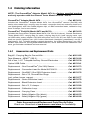
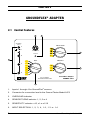
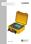
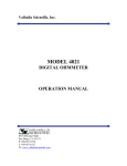
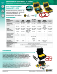
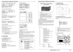
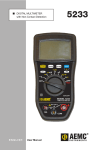
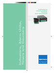
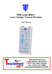
GROUNDFLEX® ADAPTER ENGLISH User Manual 6474 Statement of Compliance Chauvin Arnoux®, Inc. d.b.a. AEMC® Instruments certifies that this instrument has been calibrated using standards and instruments traceable to international standards. We guarantee that at the time of shipping your instrument has met its published specifications. NIST traceable calibration is only possible when the Model 6474 is connected to the Ground Tester Model 6472. To obtain NIST calibration (for a nominal charge), the instrument would need to be returned to our facility, along with your Ground Tester Model 6472. The recommended calibration interval is 12 months and begins on the date of receipt by the customer. For recalibration, please use our calibration services. Refer to our repair and calibration section at www.aemc.com. Serial #: _________________________________ Catalog #: _______________________________ Model #: 6474 Please fill in the appropriate date as indicated: Date Received: __________________________________ Date Calibration Due: ________________________ Chauvin Arnoux®, Inc. d.b.a AEMC® Instruments www.aemc.com Table of Contents 1.INTRODUCTION................................................................................ 3 1.1 International Electrical Symbols............................................................4 1.2 Definition of Measurement Categories..................................................4 1.3 Receiving Your Shipment......................................................................4 1.4 Ordering Information.............................................................................5 1.4.1 Accessories and Replacement Parts.......................................5 2.GROUNDFLEX® ADAPTER................................................................. 6 2.1 Control Features...................................................................................6 2.2 GroundFlex® Sensor.............................................................................7 2.2.1 Calibration of GroundFlex® Sensors........................................8 2.3 Measurements in AUTO Mode............................................................10 2.3.1 Preparation of the GroundFlex® Adapter................................10 2.3.2 Making a Measurement (Resistance of Legs).......................12 2.3.3 Other Measurements.............................................................14 2.4 MANUAL Mode and SWEEP Mode....................................................14 3.SPECIFICATIONS........................................................................... 16 3.1Electrical..............................................................................................16 3.2 Mechanical..........................................................................................18 3.3Environmental.....................................................................................18 3.4 Safety..................................................................................................18 4.MAINTENANCE.............................................................................. 19 4.1 Maintenance.....................................................................................19 4.2 Cleaning............................................................................................19 Repair and Calibration.........................................................................................20 Technical and Sales Assistance..........................................................................20 Limited Warranty.................................................................................................21 Warranty Repairs.................................................................................................21 2 GroundFlex® Adapter Model 6474 CHAPTER 1 INTRODUCTION WARNING These safety warnings are provided to ensure the safety of personnel. Please read and comply with these precautions: • This instrument is protected from accidental voltages of not more than 50V with respect to earth in measurement CAT IV. The guaranteed level of protection of this equipment may be compromised if used in a manner not specified by the manufacturer. • Safety is the responsibility of the operator. • All metal objects or wires connected to the electrical system should be assumed to be lethal until tested. Grounding systems are no exception. • Never exceed the maximum rated voltage and current, and the measurement category. • Never exceed the protection limits, and always comply with the conditions and place of use, indicated in the specifications. • Do not use the instrument or its accessories if they appear damaged. • Use accessories that have overvoltage category and service voltages greater than or equal to those of the instrument (CAT IV 50V). Use only accessories that comply with safety standards (IEC 61010-2-031 & 32). • Wear the appropriate protective gear (insulating boots and gloves). • Check that no terminal is connected and the switch is set to OFF before opening the device. • Use only the charging unit supplied with the instrument to recharge the battery. • Troubleshooting and metrological verification procedures must only be performed by qualified, approved personnel, or the factory. • NOTE: The potentials on the various rods used for an earth measurement may be different if a nearby electrical installation is defective or certain weather conditions prevail (thunderstorms). It is up to the operator to decide whether to continue or postpone measurements in these situations. GroundFlex® Adapter Model 6474 3 1.1 International Electrical Symbols Signifies that the instrument is protected by double or reinforced insulation. This symbol on the instrument indicates a WARNING that the operator must refer to the user manual for instructions before operating the instrument. In this manual, the symbol preceding instructions indicates that if the instructions are not followed, bodily injury, installation/sample and/or product damage may result. Risk of electric shock. The voltage at the parts marked with this symbol may be dangerous. Ground/Earth symbol In conformity with WEEE 2002/96/EC 1.2 Definition of Measurement Categories CAT I: For measurements on circuits not directly connected to the AC supply wall outlet such as protected secondaries, signal level, and limited energy circuits. CAT II: For measurements performed on circuits directly connected to the electrical distribution system. Examples are measurements on household appliances or portable tools. CAT III:For measurements performed in the building installation at the distribution level such as on hardwired equipment in fixed installation and circuit breakers. CAT IV:For measurements performed at the primary electrical supply (<1000V) such as on primary overcurrent protection devices, ripple control units, or meters. 1.3 Receiving Your Shipment Upon receiving your shipment, make sure that the contents are consistent with the packing list. Notify your distributor of any missing items. If the equipment appears to be damaged, file a claim immediately with the carrier and notify your distributor at once, giving a detailed description of any damage. Save the damaged packing container to substantiate your claim. 4 GroundFlex® Adapter Model 6474 1.4 Ordering Information NOTE: The GroundFlex® Adapter Model 6474 is a factory supplied product and only operates with the Ground Tester Model 6472 Kit - 500 ft. GroundFlex® Adapter Model 6474..................................................Cat. #2136.01 Includes the GroundFlex® Adapter Model 6474, four GroundFlex® sensors (5m/16ft) with twelve color-coded rings, carrying case for meter, connection lead, two extension leads on H reel (black/green) with color-coded alligator clips, six BNC extension leads, calibration loop, three C-clamps, and a user manual. GroundFlex® Field Kit (Model 6472 and 6474)..............................Cat. #2136.03 Includes the GroundFlex® Adapter Model 6474 (Cat. #2136.01 above), Ground Resistance Tester Model 6472, carrying bag for meter, carrying bag for kit, hard carrying case, optical USB cable, power adapter 110/240V with power cord 115V US, two 500 ft color-coded leads on spools (red/blue), two 100 ft color-coded leads (hand-tied, green/black), one 30 ft lead (green), four T-shaped auxiliary ground electrodes, set of five spaded lugs, one 100 ft AEMC® tape measure, rechargeable NiMH batteries, and a USB stick with DataView® software, ground tester workbook and user manual. 1.4.1 Accessories and Replacement Parts Bag #6 - Carrying Bag for Ground Kits.............................................. Cat. #2119.82 Tape Measure - AEMC® (100 ft)........................................................Cat. #2130.60 Set of two, 14.5" T-shaped Auxiliary Ground Electrodes...................Cat. #2135.39 Optical USB Cable............................................................................Cat. #2135.41 Replacement - One GroundFlex® (5m /16ft) Sensor..........................Cat. #2135.73 Replacement - Connection Lead for Model 6472/6474.....................Cat. #2135.75 Replacement - One BNC (15m /50ft) Extension Lead.......................Cat. #2135.76 Replacement - Set of 12, GroundFlex® Rings (red, yellow, brown, orange)..............................................................Cat. #2135.77 Replacement - Green Extension Lead..............................................Cat. #2135.78 Replacement - Black Extension Lead...............................................Cat. #2135.79 Replacement - Set of 3, C-clamps....................................................Cat. #2135.80 Replacement - Calibration Loop........................................................Cat. #2135.82 Replacement - Carrying Case...........................................................Cat. #2135.83 Replacement - Safety Alligator Clip (black).......................................Cat. #2140.53 Replacement - Safety Alligator Clip (green)......................................Cat. #2140.69 Order Accessories and Replacement Parts Directly Online Check our Storefront at www.aemc.com/store for availability GroundFlex® Adapter Model 6474 5 CHAPTER 2 GROUNDFLEX® ADAPTER 2.1 Control Features 2 3 GroundFlex ® Sensor SENSOR TURNS 1 50V CAT IV To Model 6472 4 Overload 2 1 1 3 SENSITIVITY INPUT 2 3 4 5 1-2 4 1-2-3 1-2-3-4 GroundFlex® Adapter MODEL 6474 For Use with the Ground Tester Model 6472 6 1. Inputs 1 through 4 for GroundFlex® sensors 2. Connector for connection lead to the Ground Tester Model 6472 3. OVERLOAD indicator 4. SENSOR TURNS selector: 1, 2, 3 or 4 5. SENSITIVITY selector: x10, x1 or x1/10 6. INPUT SELECTION: 1, 2, 3, 4, 1-2, 1-3 or 1-4 6 GroundFlex® Adapter Model 6474 2.2GroundFlex® Sensor The GroundFlex® sensors are placed around a conductor (tower leg or pole) and closed using a screw connector, which is part of the sensor. This closed loop is then used to make a contact-free measurement of the current flowing in the conductor (leg) it is wrapped around. These sensors are current measurement clamps but are able to enclose objects that are much larger. GroundFlex® sensors are available in lengths of up to approx 24 ft (8m) and can be placed around objects (such as tower legs) up to in approx 8 ft diameter (2.7m). GroundFlex® Sensor 1 50V CAT IV To Model 6472 Overload 2 INPUT 3 1-2 4 1-2-3 1-2-3-4 GroundFlex® Adapter Model 6474 7 2.2.1 Calibration of GroundFlex® Sensors Calibration is necessary for a new sensor, one that is no longer identified when a sensor has been replaced, or more than 2 lengths of extension cable is used. The calibration coefficients are then stored in the Model 6474. NOTE: Do not move or touch the GroundFlex® sensor or the calibration loop during the calibration. This could cause errors. Start by identifying each sensor using the identification rings that are supplied with the Model 6474: (1) Brown (2) Red (3) Orange (4) Yellow • Connect the calibration loop between terminals H and E of the Model 6472. • Connect the Model 6472 and 6474 together using the connection cable. • Connect the GroundFlex® sensor with the Brown ring to Input 1 of the Model 6474, the one with the Red ring to Input 2, the one with the Orange ring to Input 3, and the one with the Yellow ring to Input 4. • Coil the GroundFlex® sensor four times around in the calibration loop and close it using its screw connector. Place the connector as far as possible from the calibration device. 6472 8 6474 GroundFlex® Adapter Model 6474 1. Set the switch of the 6472 to SET-UP. 2. Set the SENSOR TURNS switch to 4. 3. Set the SENSITIVITY switch to x1. 4. Set the INPUT SELECTION switch to 1. SENSOR TURNS SENSITIVITY 1 INPUT 2 3 4 1-2 1-2-3 1-2-3-4 5. Press the Hz/OPTIONS button 5 times. The device starts by comparing the current IInt injected by the device into the calibration loop to the current IA measured by the GroundFlex® sensor. If they are different, the "CAL" symbol blinks to recommend a calibration. 1 Sx1 4 H m A x5 mA E AUTO NOTE: To avoid measurement errors, do not touch the GroundFlex® sensor or the calibration loop during the calibration. GroundFlex® Adapter Model 6474 9 6. To start the calibration, press 2nd + START. 7. The device calculates and stores a calibration coefficient for the GroundFlex® sensor connected to channel 1. 1 Sx1 4 H m A mA E AUTO This operation must be repeated for channels 2, 3 and 4; the INPUT SELECTION switch must be set to the corresponding position each time. The calibration values are now stored into memory. After calibration, the GroundFlex® sensors must always be connected to their respective channels. NOTE: Always connect the same sensor to the same input. 2.3 Measurements in AUTO Mode 2.3.1 Preparation of the GroundFlex® Adapter The GroundFlex® Adapter Model 6474 is designed to be used only with the Model 6472 device. The two instruments must be connected using the special connection cable supplied. The Model 6474 has no ON/OFF button, and is powered only by the Model 6472, via this connection cable. The Model 6474 is intended primarily to measure the current that flows through a high-voltage tower to the ground. You can wrap up to 4 legs of the towers each with a GroundFlex® sensor and measure the current flowing to earth through each of the legs or through several legs. 1. Set the rotary function switch to GroundFlex® on the Model 6472. When you connect the GroundFlex® Adapter Model 6474 to the 6472, a selftest will begin. During this test, the OVERLOAD check light on the 6474 is lit. 2. Connect the required number of sensors to channels 1, 2, 3, and/or 4. 10 GroundFlex® Adapter Model 6474 NOTE: • The sensors have arrows to indicate a direction. • All sensors should face the same direction. (clockwise or counter-clockwise around the tower legs) • All sensors should have the same number of wraps. • Sensors should encircle both leg AND ground system. To the Model 6472 6474 3. On the Model 6474, set the INPUT selection switch accordingly. You can measure the current flowing through one GroundFlex® sensor (1, 2, 3, or 4), or through several sensors (1, 2 or 1, 2, 3), or through all of the sensors (1, 2, 3, 4). 4. Select how many times the sensor is wrapped around the conductor to be measured (from 1 to 4 turns) using the SENSOR TURNS selection switch. NOTE: To increase measurement sensitivity, we recommend when possible, wrapping a maximum number of turns (up to 4) around the structure. 5. Set the SENSITIVITY switch to the desired sensitivity: x1/10, x1, or x10. The choice of sensitivity depends on the expected current value. As a precaution, always start with the lowest sensitivity, x1/10, and increase it as needed. GroundFlex® Adapter Model 6474 11 2.3.2 Making a Measurement (Resistance of Legs) 1. Place auxiliary electrodes H (Z) and S (Y) on opposite sides of the tower, as far away as possible (100-150 ft) and, if possible, perpendicular to the highvoltage line (depth is not important). This will eliminate interference with the measurement by stray voltages or currents induced under the high-voltage line. NOTE: The H (Z) and S (Y) electrodes can be placed in the same direction if necessary. In this case, the S (Y) electrode should be placed at 62% the distance of H (Z). 2. In order to avoid electromagnetic interference, it is best to unwind the full length of each cable from the reel, to keep the cables as far apart as possible on the ground, taking care not to form loops, and to avoid placing the cables near or parallel to metallic conductors (cables, rails, fences, etc.). Effects of interference are measured in milli-ohms. 3. Connect these auxiliary electrodes to the terminals H (Z) and S (Y) on the Model 6472's front panel. 4.Important: The terminals ES (Xv) and E (X) must be connected to a conducting metallic part of the tower located above the GroundFlex® sensors. This ensures measurement of the current flowing downward and towards the earth (otherwise, you would measure the current flowing upward, from the earth to the top of the tower). This will tell the condition of the overhead ground conductor. 5. Connect the required number of GroundFlex® sensors to channels 1, 2, 3, and/or 4 (the channels for which they are calibrated) and place the GroundFlex® sensors around the legs of the tower. NOTE: The direction of coiling of the sensors around tower legs have no effect on the measurement, but all of the GroundFlex® sensors must be coiled in the same direction and have the same orientation (check arrow direction on the sensor) and they must all have the same number of turns. Sensors should encircle both leg AND ground system. 12 GroundFlex® Adapter Model 6474 Overhead earth wire RH H High-voltage lines S ES E 4 GroundFlex® sensors connected with the same orientation 6472 1 2 3 4 6474 RS WARNING: If the GroundFlex® Adapter Model 6474 is connected to the earth tester, the earth potential connected to the terminals E (X) and ES (Xv) will also be present at the BNC connectors of the GroundFlex® sensors and at the connecting cable between the adapter and tester. Whenever any doubt exists about this earth potential, the user should proceed to a voltage measurement using the S (Y) and ES (Xv) terminals of the tester. 1. Set the 3 switches (Inputs, Turns and Sensitivity) of the GroundFlex® Adapter according to the connection made. 2. Start the measurement by pressing the START/STOP button. 2 Sx1 H 1 kΩ S V ES mA E AUTO To display the measurement parameters, press DISPLAY several times. GroundFlex® Adapter Model 6474 13 The device displays the following parameters: RSEL, US-ES and its frequency, ISEL, R-Act (RPASS), U-Act (US-ES and its frequency, UH-E and its frequency), I-Act (ISEL and its frequency). To measure the resistances of electrodes H (Z) and S (Y), or if the resistance of the electrodes is too high, start the measurement by a long press (approx 2 sec) of the START/STOP button (you will hear a 2nd beep). RH, RS, UH-E, IH-E will be displayed. 2.3.3 Other Measurements As explained in Step 4 on the previous page, terminals ES (Xv) and E (X) must be connected to a metallic part of the tower above the GroundFlex® sensor in order to measure the current flowing ISEL downward through the sensor towards the earth to measure ground resistance of the leg. If connections ES (Xv) and E (X) are placed below the GroundFlex® sensor, the latter measures the current flowing towards the top of the tower via the overhead ground conductor at its top, and you can in this way evaluate the quality of this overhead ground conductor. You can even make this measurement without moving the contacts of ES (Xv) and E (X) on the tower by simply passing the 2 connecting cables through the GroundFlex® sensor. The current in connecting cable E (X) and the current through the leg of the tower then cancel each other out. You can also measure any leakage currents (I-Act) flowing through each leg of the tower in normal operation of the high-voltage line. If you find different leakage currents in each leg, but they cancel out when added together, you can conclude that these currents, induced by the rotating field of the high-voltage lines, indicate an earthing fault of the tower via the overhead ground wire at the tip of the mast. 2.4 MANUAL Mode and SWEEP Mode Use the Hz/OPTIONS button and ► button to change to MANUAL mode. The following parameters can be modified: • 128Hz blinks Change the test frequency • Test voltage blinks Switch between 16 and 32V You can also perform a frequency sweep and a smoothing. 14 GroundFlex® Adapter Model 6474 In the sweep mode, the measurements can be made at frequencies up to 5kHz. On a single tower, frequencies in the order of 5kHz do not always entail inductive effects, but the "current loops" formed by the adjacent towers and the return channel through the ground may result in inductances that can be detected only at high frequencies. An equivalent diagram of the components forming this circuit is as follows: L L L Overhead earth wire Point of injection of the current Rpylon Next pylon to the left Pylon measured Next pylon to the right A measurement in sweep mode (SWEEP) of an installation like this having 10 towers gives the following results assuming an earth resistance Rpylon of 10Ω for each tower and an inductance L of 550µH for the link via the overhead ground conductor at the tip of the towers: Impedance of the towers 16 Z (ohm) 14 12 10 8 6 4 2 F (Hz) 0 0 1000 2000 3000 4000 5000 Measurement of a tower earth impedance with GroundFlex® sensors Conventional 4 pole measurement Measurement into the top of a tower (iterative network impedance) GroundFlex® Adapter Model 6474 15 CHAPTER 3 SPECIFICATIONS 3.1Electrical Measuring Method: Voltage/Current measurement with a rectangular AC signal Short Circuit Current: > 200mAAC Noise Suppression: > 80 dB at frequencies differing by 20% or more from the test frequency Max. Overload: 250Vrms Max. Value for RH & RS: 100kΩ Measuring Time: Short push on START: approx. 7 s for first value of RE at 128Hz, then 3 measurements per s. Long push on START: approx. 15 s for first value of RE at 128Hz, then 3 measurements per s. Pylon Measurement with GroundFlex® Measurement Range 0.067 to 9.999Ω 10.00 to 99.99Ω 100.0 to 999.9Ω 1.000 to 9.999kΩ 10.00 to 99.99kΩ Resolution 0.001Ω 0.01Ω 0.1Ω 1Ω 10Ω Test Voltage 16 or 32V user selectable Frequency From 41 to 128Hz selectable Resistance Measurement Frequency From 41 to 5078Hz selectable Accuracy ±5% of Reading + 1ct @ 128Hz The intrinsic error specified refers to reference conditions with a test voltage of 32V, test frequency of 128Hz, RH, and RS = 1kΩ, no external voltage. The operating error for measurements of RH, RS and RE is the same as that specified for 4-Pole earth resistance measurement. The operating error of AC resistance measurements can be less than that specified for voltage or current because frequency characteristics of the voltage channel are matched to those of the current channel. 16 GroundFlex® Adapter Model 6474 For test frequencies between 41 and 5087 Hz, between 1 and 4 turns of the GroundFlex® sensor, and a selection of 1 to 4 measurement channels, the operating accuracies are the following: SENSITIVITY and minimum ISEL minimal S x 1/10 Sx1 S x 10 Operating accuracy for RS-ES ISEL > 10mA ± (10% + 4cts) ISEL > 5mA ± (5% + 4cts) ISEL > 5mA ± (5% + 4cts) 5mA > ISEL > 0.5mA ± (15% + 10cts) Current Measurement with GroundFlex® Measurement Range 0.0 to 99.9mA (1) Resolution 0.1mA (1) 100 to 999mA 1.00 to 9.99A 10.0 to 99.9A 1mA 0.01A 0.1A Frequency 16 to 400Hz Accuracy <5% of Reading @ 50/60Hz (1): Valid only in the SENSITIVITY x 10 setting The current measured depends on the number of turns of the GroundFlex® sensor around the conductor to be measured. (e.g. if the GroundFlex® sensor is wrapped 4 times around a conductor carrying a current of 1A, the input signal will be the same as if the GroundFlex® sensor were wrapped once around a conductor carrying a current of 4A. The operating error is therefore indicated for an input signal current in A.tr (Ampere.turns). The minimum current measured depends on the setting of the SENSITIVITY switch as indicated by the table below: SENSITIVITY IMIN (A.tr) Points additional error (pt-er) x 10 0.01 5 x1 0.04 2 x 1/10 0.16 2 Accuracy Current (A * turn) 16 to 49Hz 50 to 99Hz 100 to 400Hz IMIN to 0.399 ± (20% + pt-er) ± (5% + pt-er) ± (3% + pt-er) 0.4 to 39.9 ± (10% + 2ct) ± (3% + 2ct) ± (3% + 2ct) 40 to 99.9 ± (10% + 2ct) ± (3% + 2ct) ± (20% + 2ct) GroundFlex® Adapter Model 6474 17 3.2Mechanical Dimensions: 10.7 x 9.76 x 5.12" (272, 248 x 130mm) Weight: 7 lbs (3.2kg) approx Case Material: ULV0 Polypropylene Terminals: 4mm recessed banana jacks Case Protection: EN 60529 - IP53 (cover closed) Drop Test: Per EN 61010-1 Vibration Test: Per EN 61557-1 3.3Environmental Operating Temperature: 32° to 113°F (0° to 45°C); 0 to 90% RH Specified Operating Temperature(1): 0° to 95°F (0° to 35°C); 0 to 75% RH Storage Temperature: -40° to 158°F (-40° to 70°C); 0 to 90% RH Altitude: < 3000m (1): This range corresponds to the one defined by standard EN 61557, for which an operating error including the quantities of influence is defined. When the device is used outside this range, 1.5%/10°C and 1.5% between 75 and 90% RH must be added to the operating error. 3.4Safety Electromagnetic Compatibility This instrument satisfies the EMC and LVD directives required for the CE marking and product standard IEC 61326-1 (Ed. 97) + A1 (Ed. 98). • Immunity in industrial environment • Emissions in residential environment. Electrical safety according to EN 61010-1 (Ed. 2 of 2001) Measurement according to EN 61557 (Ed. 2 of 2007) parts 1, 4 and 5. CAT IV, 50V Pollution Degree 2 *All specifications are subject to change without notice 18 GroundFlex® Adapter Model 6474 CHAPTER 4 MAINTENANCE 4.1 Maintenance Please make sure that you have read and fully understand the WARNING section on page 3. • To avoid electrical shock, do not attempt to perform any servicing unless you are qualified to do so. • To avoid electrical shock and/or damage to the instrument, do not get water or other foreign agents into the case. • Turn the instrument OFF and disconnect the unit from all circuits before opening the case. • Use specified spare parts only. 4.2 Cleaning Disconnect the instrument from any source of electricity. Use a soft cloth lightly moistened with soapy water. Wipe with a moist cloth and then dry with a dry cloth. Never use alcohol, solvents or hydrocarbons. GroundFlex® Adapter Model 6474 19 Repair and Calibration To ensure that your instrument meets factory specifications, we recommend that it be scheduled back to our factory Service Center at one-year intervals for recalibration, or as required by other standards or internal procedures. For instrument repair and calibration: You must contact our Service Center for a Customer Service Authorization Number (CSA#). This will ensure that when your instrument arrives, it will be tracked and processed promptly. Please write the CSA# on the outside of the shipping container. If the instrument is returned for calibration, we need to know if you want a standard calibration, or a calibration traceable to N.I.S.T. (Includes calibration certificate plus recorded calibration data). Ship To: Chauvin Arnoux®, Inc. d.b.a. AEMC® Instruments 15 Faraday Drive Dover, NH 03820 USA Phone:(800) 945-2362 (Ext. 360) (603) 749-6434 (Ext. 360) Fax: (603) 742-2346 or (603) 749-6309 E-mail:[email protected] (Or contact your authorized distributor) Costs for repair, standard calibration, and calibration traceable to N.I.S.T. are available. NOTE: You must obtain a CSA# before returning any instrument. Technical and Sales Assistance If you are experiencing any technical problems, or require any assistance with the proper operation or application of your instrument, please call, mail, fax or e-mail our technical support team: Chauvin Arnoux®, Inc. d.b.a. AEMC® Instruments 200 Foxborough Boulevard Foxborough, MA 02035 USA Phone:(800) 343-1391 (508) 698-2115 Fax: (508) 698-2118 E-mail:[email protected] www.aemc.com NOTE: Do not ship instruments to our Foxborough, MA address. 20 GroundFlex® Adapter Model 6474 Limited Warranty The Model 6474 is warranted to the owner for a period of one year from the date of original purchase against defects in manufacture. This limited warranty is given by AEMC® Instruments, not by the distributor from whom it was purchased. This warranty is void if the unit has been tampered with, abused or if the defect is related to service not performed by AEMC® Instruments. For full and detailed warranty coverage, please read the Warranty Coverage Information, which is attached to the Warranty Registration Card (if enclosed) or is available at www.aemc.com. Please keep the Warranty Coverage Information with your records. What AEMC® Instruments will do: If a malfunction occurs within the one-year period, you may return the instrument to us for repair, provided we have your warranty registration information on file or a proof of purchase. AEMC® Instruments will, at its option, repair or replace the faulty material. REGISTER ONLINE AT: www.aemc.com Warranty Repairs What you must do to return an Instrument for Warranty Repair: First, request a Customer Service Authorization Number (CSA#) by phone or by fax from our Service Department (see address below), then return the instrument along with the signed CSA Form. Please write the CSA# on the outside of the shipping container. Return the instrument, postage or shipment pre-paid to: Ship To: Chauvin Arnoux®, Inc. d.b.a. AEMC® Instruments 15 Faraday Drive • Dover, NH 03820 USA Phone:(800) 945-2362 (Ext. 360) (603) 749-6434 (Ext. 360) Fax: (603) 742-2346 or (603) 749-6309 E-mail:[email protected] Caution: To protect yourself against in-transit loss, we recommend you insure your returned material. NOTE: You must obtain a CSA# before returning any instrument. GroundFlex® Adapter Model 6474 21 01/14 99-MAN 100326 v4 Chauvin Arnoux®, Inc. d.b.a. AEMC® Instruments 15 Faraday Drive • Dover, NH 03820 USA • Phone: (603) 749-6434 • Fax: (603) 742-2346 www.aemc.com