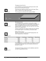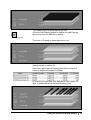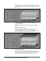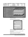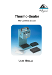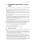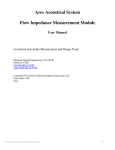
1
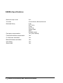
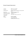
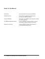
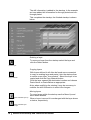
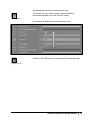
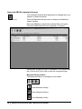
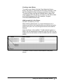
SB200a PCB Stackup and Construction Builder
SB200a User Guide
Polar Instruments Ltd
Polar Instruments Ltd.
Garenne Park
St. Sampson
Guernsey
Channel Islands
GY2 4AF
ENGLAND
Fax: +44 (0)1481 252476
email: [email protected]
http://www.polarinstruments.com
MAN 196–0402
SB200a User Guide
POLAR INSTRUMENTS LTD
COPYRIGHT
Copyright 2004 (c) by Polar Instruments Ltd. All rights reserved. This software and
accompanying documentation is the property of Polar Instruments Ltd and is licensed to
the end user by Polar Instruments Ltd or its authorized agents. The use, copying, and
distribution of this software is restricted by the terms of the license agreement.
Due care was exercised in the preparation of this document and accompanying
software. Polar Instruments Ltd. shall not be liable for errors contained herein or for
incidental or consequential damages in connection with furnishing, performance, or use
of this material.
Polar Instruments Ltd makes no warranties, either expressed or implied, with respect to
the software described in this manual, its quality, performance, merchantability, or
fitness for any particular purpose.
DISCLAIMER
1.
Disclaimer of Warranties
POLAR MAKES NO OTHER WARRANTIES, EXPRESS, IMPLIED OR STATUTORY,
REGARDING PRODUCTS. ALL OTHER WARRANTIES AS TO THE QUALITY, CONDITION,
MERCHANTABILITY, FITNESS FOR A PARTICULAR PURPOSE, OR NON-INFRINGEMENT
ARE EXPRESSLY DISCLAIMED.
2.
Limitation of Liability.
POLAR SHALL NOT BE RESPONSIBLE FOR DIRECT DAMAGES IN EXCESS OF THE
PURCHASE PRICE PAID BY THE END USER OR FOR ANY SPECIAL, CONSEQUENTIAL,
INCIDENTAL, OR PUNITIVE DAMAGE, INCLUDING, BUT NOT LIMITED TO, LOSS OF
PROFITS OR DAMAGES TO BUSINESS OR BUSINESS RELATIONS, WHETHER OR NOT
ADVISED IN ADVANCE OF THE POSSIBILITY OF SUCH DAMAGES, THE FOREGOING
LIMITATIONS SHALL APPLY, NOTWITHSTANDING THE FAILURE OF ANY EXCLUSIVE
REMEDIES.
TRADEMARKS
Copyright Polar Instruments Ltd. ©2004
Microsoft, Windows, Windows 95, Windows 98, Windows NT, Windows 2000, Windows
XP and Excel are registered trademarks of Microsoft Corporation.
IBM is the registered trademark of International Business Machines Corporation.
All other trademarks acknowledged.
SB200a Specifications
Maximum layer count
64+
Via rules
Conventional, blind and buried
Materials library
Foils
RC C foils
Cores
Pre-Preg
Solder mask
Ident
Peelable mask
Post press compensation
Yes (user defined)
Finished thickness compensation
Yes
Cu thickness calculation
Yes
Board thickness calculation
Yes
User library
Yes
Save builds
Yes
ii • SB200a PCB Stackup and Construction Builder
Personal Computer Requirements
Computer
IBM PC AT or compatible
Processor
Pentium 1GHz or better
Operating system
Windows 98 Microsoft Windows NT, Windows 2000
SP/XP
Environment
Latest .NET framework installed
System memory required
128MB recommended
Hard disk space required
200MB (min.)
Video standard
SVGA (1024 x 768 min.) Hi color 16 bit
CDROM drive
Mouse
Microsoft compatible
Licensing
Fixed: Parallel/USB key
Floating FLEXlm licence
(Windows and Linux servers only)
Personal Computer Requirements • iii
Guide To The Manual
Introduction
Introduces the Polar Instruments SB200a.
Installation/set up
Instructions for installing/uninstalling and
activating the SB200a software.
Using the SB200a
Discussion of the SB200a user interface; creating
and editing stackups.
The SB200a Materials libraries
Using the SB200a materials libraries, creating
new libraries, adding material to the library.
Design rule checking
Using the SB200a Design Rule Checker to
correct stackup design errors.
iv • SB200a PCB Stackup and Construction Builder
Contents
SB200a Specifications
ii
Personal Computer Requirements
iii
Guide To The Manual
iv
Contents
v
Introduction to the SB200a
1
The SB200a Stackup Builder
Materials library
Preferred builds
Dimensional information
Graphical interface
Installing the SB200a
Activating the SB200a
Licensing the SB200a using FLEXlm
Installing the software key
Uninstalling the software
Using the SB200a Stackup Builder
The SB200a Stackup and Construction Builder
The SB200a Menu System
The File menu
Saving stackups
Backing up stackups and libraries
The Edit menu
The Edit menu
The View menu
The SB200a toolbar
File operations
Adding layers to the stackup
Editing the stackup
Changing the stackup view
Managing the materials library
Creating a new stackup
Adding layers to the stackup
Adding a core layer
Editing the selected layer properties
Adding data file names
Changing a layer function
1
1
1
1
2
3
3
3
4
4
5
5
6
6
6
6
6
6
7
7
7
7
8
8
8
9
9
9
11
11
12
Contents • v
Exchanging layers
Adding Prepreg layers
Adding a layer of copper foil
Adding solder mask layers
Adding the Ident layers
Adding drill information
Deleting a layer
Copying layers
Moving layers
Displaying the stackup in 2-dimensional view
Using the SB200a materials libraries
Materials library toolbar
Creating a new library
Adding material to the library
Design Rule Checking
Viewing design rule errors
Correcting design rule errors
FLEXlm server-side installation
Step 1 – Starting the installer
Step 2 – Running LMTOOLS
Step 3 – Creating the HOSTID file
Step 4 – Configuring the SB200a service
Step 5 – Starting the server
Step 6 – Verifying the SB200a service
vi • SB200a PCB Stackup and Construction Builder
12
12
13
14
14
15
16
16
16
17
18
18
19
19
20
20
21
22
22
22
23
23
25
25
Introduction to the SB200a
The SB200a Stackup Builder
The Polar SB200a PCB Stackup and Construction Builder is
designed to reduce the amount of time consumed in PCB
stackup documentation and control. The SB200a offers both
interconnect designers (PCB layout engineers) and PCB
front-end engineers a fast and professional solution to layer
stackup creation. The SB200a is both graphical and easy to
use while providing formal documentation for everyone
involved in ensuring the correct materials are used in the
build process.
The SB200a allows the user to view stackup in 2d or 3d
format. Layer and material annotation is clear and easy to
read and each layer may be selected and queried to display
the associated material type and properties, including the
associated data file. Visible drill information ensures that
designers instantly know which layers support conventional,
blind and buried vias.
Materials library
The SB200a supports a flexible materials library. This allows
the designer to use standard materials data, and also
provides the facility to create new material libraries. PCB
fabricators can also build libraries of commonly stocked
materials to give interconnect designers visibility of materials
held in stock.
Preferred builds
PCB fabricators are able to create and share preferred builds
and exchange this information with designers. Build
information also includes blind and buried via information.
This simplifies the task of sharing stackup and drilling
information between board shops and the design community.
Dimensional information
Finished thickness is a critical dimension in many
applications, the SB200a keeps track of finished thickness
and tolerance, and allows fabricators the flexibility of adding
in house post press thickness for pre preg layers.
Additionally the SB200a takes into account plating thickness
where appropriate.
Introduction to the SB200a • 1
Graphical interface
The SB200a offers an easy to interpret graphical interface.
Clearly showing the layers supporting blind and buried vias,
the SB200a also records the data file for each layer
(including ident and peelable mask layers). The graphical
interface is especially designed to simplify the process of
communication between interconnect designer and
fabricator. OEMs who need to manage boards sourced from
multiple suppliers will also find this facility invaluable. In
addition to physical layers the SB200a adds mask and
notation for electrical layers.
2 • SB200a PCB Stackup and Construction Builder
Installing the SB200a
Activating the SB200a
Activation will depend on the license purchased. It will be
necessary to activate the product license prior to performing
calculations with the SB200a. The SB200a is licensed using
the FLEXlm License Manager or a software key connected to
either the parallel port (typically LPT1) or a USB port. The
FLEXlm licensing files should be installed and running on a
locally accessible server. The server must be running to
manage licensing.
Licensing the SB200a using FLEXlm
When the first stackup build is performed the SB200a
FLEXlm License finder asks for the name of the License
Server or License File.
Ensure the Specify the license Server option is selected
and press Next.
Enter the name of the License Server and press Next.
The name will normally be the Network Identification name of
the computer acting as the Licensing Server.
Installing the SB200a • 3
The SB200a will perform stackup builds within the terms of
the license purchased.
Installing the software key
If a software key is used insert the key into the parallel
printer port or USB port; if required, plug the printer cable
into the software key.
Note: If installing the software key on a Microsoft Windows
NT or Windows 2000/XP system it will be necessary to be
logged on as Administrator.
Uninstalling the software
To uninstall the SB200a software click the Windows Start
button and choose Settings and Control Panel.
Double-click Add/Remove Programs and choose SB200a
from the list. Click Remove.
4 • SB200a PCB Stackup and Construction Builder
Using the SB200a Stackup Builder
The SB200a Stackup and Construction Builder
Double-click the SB200a icon to start the SB200a program.
The main screen is displayed.
The SB200a screen comprises:
•
The menu bar — drop-down menus containing all the
SB200a commands
•
The tool bar — incorporating short cut tool buttons to
the most common menu commands
•
The stackup build and construction window — where
the board stack up is built and edited
•
Stack Up Notes/DRC — a free form text area for
explanatory or commentary notes/DRC
•
Stack Up Information properties area — table
containing information related to the whole stackup.
•
Selected Item Information area — properties table
containing the attributes of the layer currently selected
in the stackup
Using the SB200a Stackup Builder • 5
The SB200a Menu System
The File menu
The File menu allows for creation of new stackups, opening,
saving and printing existing stackups.
Saving stackups
Click the Save button to save the stackup. Users are
recommended to save the stackup frequently during the
stackup creation process to avoid data loss.
Backing up stackups and libraries
Stackup files (assigned the .stk extension) and library files
(assigned the .mlb extension) should be backed up to a
secure location.
The Edit menu
The Edit menu
The Edit menu contains most of the commands necessary to
create and modify board stack ups. The designer/fabricator
works within the free-form stackup build and construction
window and adds layers of core, prepreg, foil, etc., from the
materials library.
Layers can be moved up or down or copied and pasted, or
assigned properties as required. The SB200a will apply
design rules to the finished stackup to ensure compliance
with good board design, (for example, the SB200a will check
for symmetrical layers.)
6 • SB200a PCB Stackup and Construction Builder
The View menu
The View menu allows the SB200a to display the stackup in
a 2-dimensional or 3-dimensional aspect.
The SB200a toolbar
The SB200a toolbar comprises shortcut links to the most
popular commands.
Pause the mouse over each tool button to display the tool’s
screen tip
File operations
Create new stackup
Open existing stackup
Save stackup/changes
Adding layers to the stackup
Add foil layer to the stackup
Add resin coated copper layer
Add prepreg layer
Add core layer
Add solder mask
Add screened ident layer
Add peelable mask
Add mechanical/laser drill between layers
Using the SB200a Stackup Builder • 7
Editing the stackup
Delete selected stackup layer or drill
Swap selected material
Display properties dialog for the selected layer or drill
Copy material of the selected layer
Paste material above selected layer
Paste material below selected layer
Set the selected electrical layer as a signal layer
Set the selected electrical layer as a plane
Move selected layer up one layer
Move selected layer down one layer
Changing the stackup view
Display 2-dimensional view
Display 3-dimensional view
Managing the materials library
Display materials library
8 • SB200a PCB Stackup and Construction Builder
Creating a new stackup
The SB200a allows the designer to add or edit stackup
layers in any order, from top to bottom, bottom to top or from
the center layer outwards. In this example we create a four
layer stackup, starting at the center core layer and adding
layers above and below.
Adding layers to the stackup
Display materials library
Items added to the stackup are added from the currently
open materials library. The SB200a opens Program
Files\Polar\SB200\default.mlb if it exists; if a different library
is required open it via the Materials Library command.
Note: the SB200 does not ship with the default.mlb library.
For this discussion open one of the two sample library files,
SB200 inch.mlb or SB200 mm.mlb (stored in the Program
Files\Polar\SB200\Samples folder at installation time for a
default installation.)
Caution: Consistency of units
When defining dimensions for a stackup (for example, layer
thicknesses) ensure that all measurements are defined using
the same units (mils, mm, etc) throughout the structure and
its libraries.
Note: the libraries supplied for these examples are preloaded
with sample data only.
Click File|New to clear the stackup screen and notes and
information text areas.
Save stackup button
Click the Save button to save the stackup. Users are
recommended to save the stackup frequently during the
stackup creation process to avoid data loss. Stackup files
(.stk) and library files (.mlb) should be backed up to a
secure location.
Adding a core layer
Click the Add Core button, the core library is displayed
The core library contains full details of the core material,
including base and finished thicknesses, dielectric constant,
and upper and lower copper thicknesses.
Click on the column button to sort the library list by the
selected column.
Choose a core type from the list of cores and click the Add
Above button
Using the SB200a Stackup Builder • 9
Add core above selected layer
Add core below selected layer
The core is added to the stackup screen.
Stackup core layer
As each layer is added the stackup information table is
updated to reflect the current status of the stackup.
Stackup information table
With the core selected, the Selected Item table displays the
properties of the core.
Core layer information
10 • SB200a PCB Stackup and Construction Builder
Editing the selected layer properties
To change the properties of the selected object (for example,
to modify the value for the finished thickness of the
dielectric), right click the object in the stackup and choose
Properties from the shortcut menu; the Core Properties
dialog is displayed.
Note: the on-screen descriptive text to the left of each layer
is plain free form text derived from the layer properties and
can be modified using the layer properties dialogs.
When altering descriptions, keep the description short and
avoid using dimensional information in text fields which
produce on-screen display; if the dimensions specified in the
dialog’s other text boxes are subsequently changed the onscreen description may not match the true dimensions.
Core Properties
Change the Dielectric finished thickness to the corrected
value and click Apply.
Adding data file names
If available, add the data file name(s) to the upper and lower
copper layers and click Apply.
Close the dialog when all changes are completed.
Changes will be reflected in the Stackup Information table
Using the SB200a Stackup Builder • 11
Changing a layer function
In this example we change both signal layers above and
below the core dielectric to planes.
Click the lower signal layer and click the Set Layer Plane
button. Repeat for the upper signal layer.
Set Layer Plane
The changes are reflected in the stackup window
Exchanging layers
Library Swap button
To change just the core dielectric (leaving the copper
layers unaffected) select the core material (for example the
FR4 in the graphic above) and click the Swap Selected
Material button. Choose the new core type from the library
and click the Swap button.
The layer properties will change to reflect the new material
and changes appear in the Stackup Information table.
Adding Prepreg layers
With the core selected, click the Add Prepreg button; the
Add Prepreg library is displayed.
Add Prepreg button
The Prepreg library contains details of the Prepreg material,
including the Prepreg’s base and finished thickness and
dielectric constant.
Choose the Prepreg material from the database and click
the Add Prepreg Above button.
Add Prepreg Above
12 • SB200a PCB Stackup and Construction Builder
The Prepreg layer is added above the core.
Click the Add Prepreg button to display the Add Prepreg
library and click the Add Below button
Add Prepreg Below
The layer of Prepreg is added below the core.
Adding a layer of copper foil
Select the upper layer of Prepreg and click the Add Foil
button to display the copper foil library.
Choose the foil type and click Add Above, the copper foil
layer is added above the selected Prepreg layer.
Using the SB200a Stackup Builder • 13
Repeat the procedure for the lower Prepreg layer: select the
lower Prepreg layer and add a layer of copper foil below the
layer.
To alter the foil properties, right-click the foil layer and
choose Properties.
Note the stackup is built symmetrically about the center
layer.
Adding solder mask layers
With the upper layer of foil selected, click the Add
Soldermask button to add a layer of LPI soldermask above
the foil. Repeat the process for the lower foil layer.
Adding the Ident layers
Select the lower LPI soldermask layer and click the Ident
button to add a layer of Screened Ident below the layer. The
sample Ident library includes ink thickness and color.
14 • SB200a PCB Stackup and Construction Builder
Repeat for the upper layer.
Adding drill information
To add a drill information between layers click the Add Drill
button; the Add Drill dialog is displayed.
Choose the first and second electrical layer numbers (layers
1 and 4 in the example).
Specify the drill type, mechanical or laser and whether
through plated.
Optionally, add the NC drill data filenames.
Optionally, add the hole count, number of different hole sizes
and the minimum hole size. Click Add and close the dialog.
Using the SB200a Stackup Builder • 15
The drill information is added to the stackup. In the example
we have added drill information for through plated and nonthrough plated.
This completes the stackup; the finished stackup is shown
below
Deleting a layer
To remove a layer from the stackup select the layer and
click the Delete button.
Delete layer
Copying layers
Copy Material
With layers defined it will often be found more convenient
to copy an existing layer and paste it into the stackup than
to create a new layer “from scratch”. Select the layer to be
copied and click the Copy Material button.
Click the layer nearest the destination location and choose
Paste Above or Paste Below as appropriate
Note: when modifying the stackup it may be necessary to
redefine the drill information to reflect the changes.
Moving layers
Move selected layer up
one layer
To move layers within the stackup use the Move Up and
Move down buttons.
When a layer is moved it is exchanged with the layer above
or below, respectively.
Move selected layer
down one layer
16 • SB200a PCB Stackup and Construction Builder
Displaying the stackup in 2-dimensional view
To change the view of the stackup from its default 3dimensional aspect, click the View 2D button.
View 2D button
The stackup is displayed in 2-dimensional view.
Click the View 3D button to restore the 3 dimensional view.
Display 3Dl view
Using the SB200a Stackup Builder • 17
Using the SB200a materials libraries
The materials libraries allow designers to manage their own
libraries of board materials.
Materials Library
Click the Materials Library button to display the Materials
Library window.
When the SB200a is started the material library Program
Files\Polar\SB200\default.mlb is opened (if it exists).
Each library component type is accessible via its associated
tab. Click on the Tab to view or edit the component type.
Materials library toolbar
The Materials Library is managed via its toolbar
Clear Materials Library
Open Materials Library
Save Materials Library
18 • SB200a PCB Stackup and Construction Builder
Creating a new library
To create a new library click the Clear Materials Library
button; the library is removed from the library manager. Click
the Save Materials Library button to create the new library.
To have the library load as the SB200a starts, assign the
name default.mlb to the library and save it in the same folder
as the SB200 program files (for example, Program
Files\Polar\SB200\default.mlb).
Adding material to the library
Caution: Consistency of units
When defining dimensions, e.g. layer thicknesses, for a
stackup ensure that all measurements are defined using the
same units (mils, mm, etc) throughout the structure and its
libraries.
Open the library to be modified. To add material types to a
library click the associated component type tab; click into the
empty record at the bottom of each list and enter the material
details.
To delete a record, click the record selector and press
Delete.
Using the SB200a Stackup Builder • 19
Design Rule Checking
The SB200a includes facilities to check for errors in stackup
design, such as layers placed in invalid order or
asymmetrical structures.
The Design Rule Checker (DRC) displays results in the DRC
dialog. As each design rule is broken the SB200a increments
the error count on the DRC tab.
Viewing design rule errors
Click the DRC tab to view errors.
The Design Rule Checker checks include checking for:
Two Adjacent Copper Layers
Resin Coated Copper on Internal Layer
External Prepreg
Internal Solder Mask
Internal Ident
Internal Peelable Mask
Symmetry : Different Material Types
Copper not Balanced
The errors shown in the dialog above correspond to the
stackup structure on the facing page. Errors are highlighted
in red.
20 • SB200a PCB Stackup and Construction Builder
Correcting design rule errors
Users are strongly recommended to work through and
correct errors in the order in which the errors are listed.
In the example stackup one of the Prepreg layers (shown
selected) is external to the layer of copper foil. This will result
in three errors: the External Prepreg error, the Two Adjacent
Copper Layers error and the Symmetry: Different material
types error. Placing the Prepreg layer into its correct position
in the stack will clear both errors.
The Ident layer (normally the outermost layer) is located on
an internal layer.
Two layers of copper are adjacent (effectively a short circuit
between copper layers).
The stackup is built asymmetrically.
Move the layers to their correct location in the stackup to
correct errors. Note that clearing each error may clear other
errors in the process.
Using the SB200a Stackup Builder • 21
FLEXlm server-side installation
This document describes a simple FLEXlm server-side
installation for the Polar SB200a.
Full details of the FlexLm product capabilities are contained
in the the FlexLm User Manual or on the
www.macrovision.com web site.
Note: You will need to be logged into the server with
Administrator privileges to perform this installation.
Step 1 – Starting the installer
Insert the installation disk into the CDROM drive of the
server. Start the installer via Setup.exe on the supplied disk.
This will create a folder on the server which by default is:
C:\ProgramFiles\FlexLm\V9.2
Step 2 – Running LMTOOLS
Navigate to the folder created in Step 1 and run the
LMTOOLS.exe program.
LMTOOLS dialog box
FLEXlm server-side installation • 22
Step 3 – Creating the HOSTID file
Select the System Settings tab.
LMTOOLS System Settings
The System Settings page displays critical information about
your selected server machine. Click the Save HOSTID Info
to a File button.
This will create a text file that you will need to email to:
[email protected]
Note: Please also include within the email the Company
Name that you would like associated with the licence file.
Failure to do this will result in a delay in issuing the licence.
Once Polar Instruments has received and processed this
information you will be returned a custom licence file by
email.
Note: Until the custom licence file is correctly installed on the
server machine the SB200a software cannot be used. The
custom licence file is allocated to the nominated server
machine and cannot be used on any other server.
Step 4 – Configuring the SB200a service
Once you have received your custom licence file from Polar
Instruments copy it to the same folder that currently contains
LMTOOLS.exe.
Select the Config Services tab
FLEXlm server-side installation • 23
Config Services tab
In the Service Name dropdown enter the service name:
Polar SB200a
Use the three Browse buttons to select the lmgrd.exe file,
the SB200A.lic file and the Polar SB200A.log file.
Select the Use Services and Start Server at Power Up
checkboxes.
Polar SB200a
C:\Flex\lmgrd.exe
C:\Flex\SB200a.lic
C:\Flex\PolarSB200a.log
Config Services tab
Before leaving this page select the Save Service button to
store these settings.
24 • SB200a PCB Stackup and Construction Builder
Step 5 – Starting the server
Select the Start/Stop/Reread tab
Polar SB200a
Using license file: C:\Flex\SB200a.lic
Start/Stop/Reread tab
Select the Start Server button; this should be the only time
that you are required to do this as this service will be now be
run at the time of server start up.
Step 6 – Verifying the SB200a service
Select the Service/Licence File tab
This should now show the Polar SB200a Service.
Polar SB200a
Service/Licence File tab
This completes the server side installation; please refer to
the FLEXlm User Manual for additional information.
FLEXlm server-side installation • 25