1
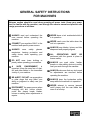
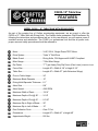
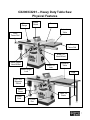
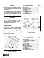
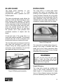
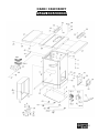
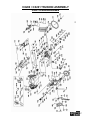
CX200-10” / CX201-10” HEAVY DUTY TABLE SAW WITH RIVING KNIFE User Manual TABLE OF CONTENTS General Safety Instructions..................................................................................... 3 Specific Safety Instructions..................................................................................... 4 CX200 Features...................................................................................................... 5 CX201 Features...................................................................................................... 6 Physical Features ................................................................................................... 7 Set Up..................................................................................................................... 8 Un-Packing & Inventory .......................................................................................... 8 Proper Grounding ................................................................................................... 10 Assembly ................................................................................................................ 11 CX200 Extension Table .......................................................................................... 13 CX201 Extension Table .......................................................................................... 14 Installing the Saw Blade.......................................................................................... 15 Fence Scale ............................................................................................................ 15 Blade Guard Installation.......................................................................................... 16 Connecting to a Dust Collector ............................................................................... 16 Basic Controls.........................................................................................................17 Test Run ................................................................................................................. 17 Blade Guard............................................................................................................ 18 Riving Knife............................................................................................................. 18 Work-Piece Inspection ............................................................................................ 19 Operations .............................................................................................................. 19 Through Cuts .......................................................................................................... 19 Non-Through Cuts .................................................................................................. 19 Ripping.................................................................................................................... 20 Crosscutting ............................................................................................................ 20 Miter Cuts ............................................................................................................... 21 Bevel Cuts .............................................................................................................. 21 Adjustments ............................................................................................................ 22 Main Table to Blade Parallelism.............................................................................. 22 Blade Guard Spreader & Riving Knife Alignment.................................................... 22 Tensioning the V-belt .............................................................................................. 23 Replacing the V-Belts ............................................................................................. 24 Maintenance ........................................................................................................... 24 Parts Breakdown & List.......................................................................................25-37 Warranty ................................................................................................................. 38 2 GENERAL SAFETY INSTRUCTIONS FOR MACHINES Extreme caution should be used when operating all power tools. Know your power tool, be familiar with its operation, read through the owner’s manual and practice safe usage procedures at all times. ALWAYS read and understand the user manual before operating the machine. CONNECT your machine ONLY to the matched and specific power source. ALWAYS wear safety glasses respirators, hearing protection and safety shoes, when operating your machine. DO NOT wear loose clothing or jewelry when operating your machine. A SAFE ENVIRONMENT is important. Keep the area free of dust, dirt and other debris in the immediate vicinity of your machine. BE ALERT! DO NOT use prescription or other drugs that may affect your ability or judgment to safely use your machine. DISCONNECT the power source when changing drill bits, hollow chisels, router bits, shaper heads, blades, knives or making other adjustments or repairs. NEVER leave a tool unattended while it is in operation. NEVER reach over the table when the tool is in operation. ALWAYS keep blades, knives and bits sharpened and properly aligned. ALL OPERATIONS MUST BE performed with the guards in place to ensure safety. ALWAYS use push sticks, feather boards or other safety devices to safely feed your work through the machine. ALWAYS make sure that any tools used for adjustments are removed before operating the machine. ALWAYS keep the bystanders safely away while the machine is in operation. NEVER attempt to remove jammed cutoff pieces until the saw blade has come to a full stop. 3 CX200/CX201 SPECIFIC SAFETY INSTRUCTIONS NEVER use a saw blade that has missing carbide teeth, loose teeth, or chipped or broken teeth. NEVER stand directly in line with the saw blade when feeding stock into the saw. NEVER place your fingers or hands in the line of cut. If you slip, your hands or fingers may come into contact with the blade. Always use a push stick when ripping narrow pieces. NEVER allow visitors or helpers to stand in line with the saw blade. ALL GUARDS must be in place while operating the table saw to ensure safety. ALWAYS feed the stock smoothly. Do not force or twist the work-piece while cutting. NEVER allow anyone to “assist” you by holding your work-piece at the outfeed end. MAKE SURE before making any adjustments, the switch is in the “OFF” position and the cord is un-plugged. NEVER LEAVE the table unattended while it is running. saw DO NOT attempt to remove jammed pieces unless the table saw has come to a complete stop and the power switch has been turned to the OFF position and cord is unplugged. NEVER attempt to cut stock “freehand”, always use the rip fence or miter gauge. ALWAYS make sure that the rip fence is properly squared to the saw blade to prevent kickback. ALWAYS make sure that your saw is in a stable position. Cutting heavy or long stock may alter the stability of the saw. In the event that this may occur, make sure that the saw should be firmly bolted to the floor. ALWAYS be sure that if using a mobile base, wheels are firmly locked before turning the saw on. ALWAYS use a feather board and/or hold-downs to support your work-piece when necessary. MAKE SURE you have read and understood all the safety instructions in the manual and you are familiar with your table saw, before operating it. If you fail to do so, serious injury could occur. WARNING The safety instructions given above can not be complete because the environment in every shop is different. Always consider safety first as it applies to your individual working conditions. 4 CX200–10” Table Saw FEATURES MODEL CX200 – 10” TABLE SAW WITH RIVING KNIFE As part of the growing line of Craftex woodworking equipment, we are proud to offer the CX200 a 10” Table Saw with Riving Knife. The Craftex name guarantees Craft Excellence. By following the instructions and procedures laid out in this user manual, you will receive years of excellent service and satisfaction. The CX200 is a professional tool and like all power tools, proper care and safety procedures should be adhered to. Motor .............................................. 3-HP, 220-V, Single Phase TEFC Motor Drive System .................................. Triple “V” Belt Drive Blade Guard ...................................Riving Knife, CSA Approved & UL897 Compliant Miter Gauge.................................... T-Slot Miter Gauge Rip Fence .......................................“T” Type Heavy Duty Rip Fence (Cam Lever) w/Optical Cursor Fence Size...................................... Length 48” x Width 4-1/8” x Height 2-1/2” Table Size....................................... Length 40” x Width 27” (with Extension Wings) Floor to Table Height ...................... 34” Maximum Blade Diameter .............. 10” Riving Knife/Spreader Thickness.... 0.1” Arbor Size....................................... 5/8” Arbor Speed ................................... 4300 RPM Maximum Width of Dado ................ 13/16” Maximum Depth of Cut @ 90°........ 3-1/8” Maximum Depth of Cut @ 45° ........ 2-3/16” Maximum Rip to Right of Blade ...... 30” Maximum Rip to Left of Blade......... 12” Dust Collection Ports ...................... One 4” Port Dimensions.....................................Length 62” x Width 41” x Height 40” Approximate Weight .......................550 lbs. 5 CX201–1” Table Saw FEATURES MODEL CX201 – 10” TABLE SAW WITH 50” RAILS & EXTENSION TABLE As part of the growing line of Craftex woodworking equipment, we are proud to offer the CX201 a 10” Table Saw with 50” Rails, Riving Knife and Extension Table. The Craftex name guarantees Craft Excellence. By following the instructions and procedures laid out in this user manual, you will receive years of excellent service and satisfaction. The CX201 is a professional tool and like all power tools, proper care and safety procedures should be adhered to. Motor .............................................. 3-HP, 220-V, 12.8 Amp, Single Phase TEFC Motor Drive System .................................. Triple “V” Belt Drive Blade Guard ...................................Riving Knife, CSA Approved & UL897 Compliant Miter Gauge.................................... T-Slot Miter Gauge Rip Fence .......................................“T” Type Heavy Duty Rip Fence (Cam Lever) w/Optical Cursor Fence Size...................................... Length 48” x Width 4-1/8” x Height 2-1/2” Table Size....................................... Length 73-3/4” x Width 27” (with Extension Wings) Floor to Table Height ...................... 34” Maximum Blade Diameter .............. 10” Riving Knife/Spreader Thickness.... 0.1” Arbor Size....................................... 5/8” Arbor Speed ................................... 4300 RPM Maximum Width of Dado ................ 13/16” Maximum Depth of Cut @ 90°........ 3-1/8” Maximum Depth of Cut @ 45° ........ 2-3/16” Maximum Rip to Right of Blade ...... 50” Maximum Rip to Left of Blade......... 12” Dust Collection Ports ...................... One 4” Port Dimensions.....................................Length 82” x Width 41” x Height 40” Approximate Weight .......................590 lbs. 6 CX200/CX201 – Heavy Duty Table Saw Physical Features Blade Guard Miter Gauge Fence Extension Table Front Fence Rail Rear Fence Rail Blade Tilt Hand Wheel Blade Height Hand Wheel Blade Tilt Lock Extension Table Blade Height Lock Legs ON / OFF Magnetic Switch Motor Cover Power Cord Table Tilt Scale 4” Dust Port 7 SETUP Before setting up your machine you should read and understand the instructions given in this manual. The unpainted surfaces of this table saw are coated with a rust preventive waxy oil and you will want to remove this before you begin assembly. Use a solvent cleaner that will not damage painted surfaces. LIST OF CONTENST A. B. C. D. E. F. G. QTY Table Saw........................................ Extension Wings .............................. Cabinet Door.................................... Fence............................................... Fence Rails & Tube ......................... 10” Blade ......................................... Magnetic Switch............................... 1 2 1 1 3 1 1 WARNING CX200/CX201 is a very heavy machine, do not over-exert yourself. For safe moving method use fork truck or get the help of an assistant or friend. UNPACKING The machine is properly packaged and shipped completely in crates for safe transportation. When unpacking, carefully inspect the crates and ensure that nothing has been damaged during transit. Open the crates and check that the machine and the parts are in good condition. Figure-2 Inventory LIST OF CONTENTS H. I. J. K. L. M. N. O. P. Q. R. QTY Table Insert ...................................... Blade Guard & Spreader.................. Push Stick........................................ Miter Gauge ..................................... Riving Knife...................................... Hand Wheel ..................................... Hand Wheel Lock............................. Hand Wheel Handle......................... Dust Port.......................................... Hardware Bag .................................. Fence Rail Tape Scale..................... 1 1 1 1 1 2 2 2 1 1 1 Figure-1 Inverntory 8 CX200 & CX201 EXTENSION TABLE While doing inventory, if you can not find any part, check if the part is already installed on the machine. Some of the parts come assembled with the machine because of shipping purposes. When setting up your machine, you will want to find an ideal spot where your table saw will most likely be positioned most of the time. Consider your complete work environment as well as working comfortability with the table saw before placing your machine in the ideal spot. Figure-3 Inventory LIST OF CONTENTS S. T. U. V. QTY Extension Wing (CX201) ................. Legs (CX201) .................................. Foot Pads........................................ Extension Wing (CX200) ................. 1 2 2 1 Figure-4 Minimum CX200 & CX201 working space for 9 PROPER GROUNDING Grounding provides a path of least resistance for electric current to reduce the risk of electric shock. WARNING CX200/CX201 is equipped with a 220-V single phase motor. Improper connection of the equipmentgrounding conductor can result in a risk of electric shock. Check with a qualified electrician if you are in doubt as to whether the outlet is properly grounded. To prevent electrical hazards, have a qualified electrician ensure that the line is properly wired. This appliance is for use on a circuit having a normal of 220 volts. Make sure that the appliance is connected to an outlet having the same configuration as the plug. If an adaptor plug is used, it must be attached to the metal screw of the receptacle. It is strongly recommended not to use extension cords with your CX200/CX201. Always try to position your machine close to the power source so that you do not need to use extension cords. Incase if you really find it necessary to use an extension cord, make sure the extension cord does not exceed 50-feet in length and the cord is 14-gauge to prevent motor damage. Your CX200/CX201 should be wired with a plug having 3-prongs to fit a 3 prong grounding receptacle as shown in figure-5. Do not remove the grounding prong to fit it into a 2-pronged outlet. Always check with a qualified electrician if you are in doubt. Figure-5 220-Volts Outlet for CX200/CX201 10 ASSEMBLY To assemble your CX200/201, read and understand the text and figures given. Install the blade tilt hand wheel onto the hand wheel shaft and secure it using set screw provided. See figure-8. Take the magnetic switch out of the saw cabinet and loosen the bolt securing the shipping brace, and remove the brace. Reinstall the bolt and washers and save the shipping brace. Figure-8 Securing the blade tilt hand wheel Now, thread the hand wheel lock into the center of the hand wheel and tighten it. Figure-6 Shipping brace location Thread the hand wheel handle onto the hand wheel and tighten using a proper size wrench. Attach the cabinet door by inserting the door pins into the hinge sockets on the cabinet. See figure-7. Figure-9 Hand wheel lock and handle installed Figure-7 Installing the cabinet door Install the blade height hand wheel in the same manner. 11 Attach the dust port to the saw and secure it using the knob as shown in figure-10. Place a straight-edge on the main table and the extension wing, and make sure they are flat with each other. If the mating surface of the extension wing tilts down, use a masking tape along the bottom edge of the main table to shim the extension wing up. Figure-10 Installing the dust port Remove the screws and washers from the edges of the main table and inspect the mating surfaces of the extension table and main table for any foreign material that can cause misalignment when assembled. Make sure the mating surfaces of the main table and the extension wings are clean and attach the extension wings to the table with the help of an assistant holding the table. Secure it using cap screws and washers provided. See figure 11. Figure-12 Using masking tape to shim the extension wing up If the mating surface of the extension wing tilts up, use a masking tape along the top edge if the main table to shim the extension wing down. Figure-13 Using masking tape to shim the extension wing down Figure-11 Installing the extension wings When the table is reinstalled, remove the excessive masking tape using a blade. 12 Attach the front fence rail to the table and the extension wing using nuts, bolts and washers provided. See figure-14. Figure-16 Installing rear fence rail Figure-14 Installing front fence rail CX200 EXTENSION TABLE Now, install the fence rail tube onto the front rail using cap screws, washers and flat washers provided. See figure-15. Install the extension table between the front and rear fence rails, securing it to the rails using hex nuts, hex bolts and washers provided. Figure-15 Installing the fence rail tube Figure-17 Installing the extension table for CX200 Attach the rear fence rail to the extension wings and the main table and secure it using hex bolts and washers provided. See figure-16. Make sure the top edge of the rear rail is flush with the bottom part of the T-slots on the table. Place a straight-edge across the extension wing and the extension table and adjust the extension table so that it is flush with the extension wings and the main table. 13 CX201 EXTENSION TABLE Get an assistant to hold the extension table between the front and rear fence rails. Secure the extension table to the rails using hex bolts, hex nuts and washers provided with the extension table. Thread the foot pads into the legs as shown in figure 18 and do not tighten the jam nut at this time. Place a straight-edge across the extension wings and the extension table and level the extension table by adjusting the feet, so that the extension is flush with the extension wings and the main table. Once the table surfaces are flush with each other, tighten the hex nuts on the feet up, against the leg to lock the feet. To install the fence, place it on the rails, on the right hand side of the blade and push the fence handle down to lock the fence on the rails. Figure-18 Connecting legs to each other Place the legs under the table and adjust the feet until the table sits properly on both legs and tighten the jam nut Secure the legs to the end of the table using cap screws and washers provided. See figure19. Figure-19 Installing CX201 extension table Figure-20 Installing the fence on the rails Attach the magnetic switch to the front rail and secure it using screws and washers. Figure-21 Installing the magnetic switch 14 INSTALLING THE SAW BLADE pointer window and re-install it on the right side of the fence. Remove the screw securing the table insert to the table and remove the table insert. Raise the arbor all the way up using the blade height hand wheel located on the front of the saw and set the blade to 0degree. Remove the arbor nut and the arbor flange and install the 10” blade provided. Make sure the teeth of the blade are facing the front of the saw. Install the arbor flange and the arbor nut and tighten using arbor wrenches provided. Figure-23 Installing pointer window To Install the Fence Scale: Slide the fence against the saw blade and push the fence handle down to lock it on the rails. Figure-22 Installing the blade FENCE SCALE Before installing the fence scale on the rail tube, determine whether you want to use the pointer window to the right or left side of the fence. It is recommended to mount the pointer window to the right side of the fence so that the work-piece does not cover the pointer window while cutting operation. If the machine comes with the pointer window mounted to the left side of the fence, simply loosen the screws on the Place the tape scale on the fence and make sure the “0” is aligned with the red line on the pointer window, and mark the “0” on the fence tube with a pencil. Remove the fence and peel off the tape. Align the “0” mark on the tape scale with the pencil mark on the tube and attach the tape scale on the tube. IMPORTANT To get accurate cuts, it is very important to attach the tape scale on the fence tube, aligning the “0” perfectly with the pencil mark that you made. Adjust the pointer window if required by loosening the two screws holding the pointer window to the fence and position it left or right. 15 INSTALLING BLADE GUARD Install the table insert and slide the knurled knob out, rotating it forward so that it engages the upper bracket. CONNECTING TO A DUST COLLECTOR CX200/CX201 features a 4” diameter dust port to connect to a dust collector. When connecting to a dust collector, use a proper sized hose and make sure all the connections are sealed tightly. It is recommended to use a proper sized dust collector with the CX200/CX201 to ensure adequate dust collection. Figure-24 Using knurled knob to secure the spreader Now, slide the blade guard spreader, down into the adjustment block and rotate the knurled knob to disengage the bracket. The locking pin engages the hole in the center of the spreader. Make sure the spreader is locked properly. Figure-26 Connecting to a dust collector The blade guard should move freely and touch the table surface and should swing high enough to allow the work-piece fed easily while cutting operation. WARNING The fine dust particles produced by the table saw can go into your lungs and cause serious respiratory problems. Make sure to wear a dust mask and connect the table saw to a proper dust collection system while operating it. Figure-25 Blade guard installed 16 BASIC CONTROLS TEST RUN The basic controls of this machine are shown in the figure-27. Use the figure and read the text to understand what the basic controls of your CX200/CX201 are. Once you have assembled your machine completely, it is then time for a test run to make sure that the machine works properly and is ready for operation. During the test run if there is any unusual noise coming from the machine or the machine vibrates excessively, stop the machine immediately and disconnect from the power source and investigate to find out the problem with your machine. Figure-27 Basic controls on CX200/CX201 Magnetic Switch The magnetic switch on your CX200/CX201 has a green button to turn the machine “ON” and a red button to turn the machine “OFF”, when pressed. Blade Height Hand Wheel It is used to raise and lower the blade. The hand wheel features a locking knob at its center, which is used to lock the hand wheel. If you want to adjust the blade height, loosen the hand wheel lock and turn the hand wheel. When the blade is at the desired height, tighten the lock. Blade Tilt Hand Wheel It is used to adjust the angle of the blade. The hand wheel features a lock in its center, which is used to lock the hand wheel. If you want to adjust the blade angle, loosen the locking knob and turn the hand wheel. When the blade is at the desired angle, tighten the lock. READ THE MANUAL Before starting the table saw, make sure that you have read and understood the manual and you are familiar with the functions and safety features on this machine. Failure to do so may cause serious personal injury. During the test run you should make sure that the machine operates properly when turned ON. Check all the safety features on the machine and make sure all the safety features work properly. WARNING The safety instructions given in this manual can not be complete because the environment in every shop is different. Always consider safety first as it applies to your individual working conditions. 17 BLADE GUARD RIVING KNIFE The blade guard assembly on your CX200/CX201 consists of a clear polycarbonate shield, spreader and antikickback pawls. The riving knife is a metal plate which prevents the newly cut work-piece from pinching at the backside of the blade and causing kickback. Basically the riving knife does the same job as the spreader. But the main difference is that the riving knife is installed below the blade height while the spreader is installed higher than the blade. The clear polycarbonate guard allows the operator to see the blade cutting the workpiece during cutting operation. The guard covers the blade on both sides and lifts up as the work-piece is fed into the blade and returns to the table surface when the workpiece has passed through the blade. It prevents the wood chips to fly and injure the operator and it also prevents from accidental contacts of objects with the blade. At the back side of the guard there is a metal plate called a spreader. The spreader prevents the kerf of the work-piece from pinching the blade and causing kick back. The kick back pawls are designed such that they allow the work-piece to move only forward. During the cutting operation if the work-piece moves backward, the anti kick back pawls will dig into it and stop it. Figure-29 Riving knife The riving knife is installed when doing nonthrough cuts using a standard table saw blade and for the cutting operations when the blade does not cut all the way through thickness of the work-piece. WARNING DO NOT use the riving knife with dado blades. If used, the riving knife will be higher than the dado blade and the workpiece will hit the riving knife. Height Difference: Figure-28 Blade guard assembly The riving knife should be installed with 1mm to 5mm height difference with the blade height. It is recommended to keep 3mm to 8mm distance between the blade (from the carbide tip) and the riving knife. 18 WORK-PIECE INSPECTION Before cutting the work-piece, make sure to inspect it for nails, staples, small pieces of stone or metal and any other object which is dangerous to come on contact with the blade. If the wood contains any of these objects and it comes in contact with the blade, the object might fly and hit the operator or seriously damage the blade. For a safe cutting method always inspect your workpiece carefully before cutting and wear eye protection. Some woods with excessive twisting or wrapping are un-stable while cutting. This situation can be dangerous, because during operation the work-piece can move unexpectedly which can either damage the blade or hurt the operator. If the wood is slightly cupped, make sure the cupped face of the wood is held against the table or the fence. If the bowed side of the work-piece is held against the table or the fence, there will be a great possibility that the work-piece move unexpectedly while cutting, and cause kickback or injury to the operator. Some stock with large knots can damage the blade and wet stock will give a poor result. WARNING The information above is just a guideline for you to understand how to cut a workpiece with slight cupping. If you are not sure and do not have any experience in cutting cupped stock, do not cut it. Failure to follow these instructions might bring personal injuries to the operator or serious damage to the blade. OPERATIONS Before doing the operation, make sure all the parts of the machine are assembled properly and you have done the test run. Make sure you have read the manual and you are familiar using the table saw, knowing all the safety features on this machine. THROUGH CUTS The operation, in which the saw blade cuts the work-piece completely, is called through cut. Ripping, cross cuts, miter cuts and beveled cuts are examples of through cuts. Figure-30 Shows an example of through cut For clarity the blade guard assembly is not shown in figure-30 but for your safety it is highly recommended to use blade guard when performing through cuts. NON-THROUGH CUT The operation, in which the work-piece is passed over the saw blade and it does not cut the work-piece all the way through its thickness, is called non-through cut. 19 Since the blade guard can not be used when doing non-through cuts, there is great possibility of kickback. Make sure to have the riving knife installed, when using standard saw blade to perform non-through cuts. reach the full speed and feed the workpiece through the blade using a push stick, until the work-piece completely passes the saw blade. See figure-32. Figure-32 Ripping operation Figure-31 shows an example of nonthrough cut with standard saw blade For clarity figure-31 does not show riving knife, but it is highly recommended to install the riving knife when performing nonthrough cuts with standard saw blade. After the work-piece is cut, let the blade come to a complete stop and then remove the cut-off pieces. WARNING RIPPING Cutting solid wood with the grain and cutting down the length of the work-piece is called ripping. With the power “OFF”, adjust the fence on the rails according to the desired width of the cut. Turn the table height hand-wheel to set the guide post assembly 1/4” above the work-piece. Make sure that blade guard assembly is working properly and install other safety devices like feather board, if needed. Connect the cord to the power source and turn the table saw “ON”. Let the blade to Do not use your fingers to feed narrow work-pieces into the blade. Always use a push stick to prevent the possibility of injury. CROSSCUTTING Cutting solid wood across the grain and cutting plywood across the width of the work-piece is called cross-cutting. Remove the fence and mark the work-piece where you want to start the cut from and make sure the miter guide is at 90° position on the miter slot. Place the work-piece on the table so that the marked point is aligned 20 with the blade and the blade is cutting the waste side of the line. Connect the cord to the power source and turn the table saw “ON”. Let the blade to reach its full speed and hold the work-piece against the face of the miter gauge. Slowly push the work-piece with the miter gauge and until it is completely past the blade. Let the blade come to a complete stop and remove the cut-off work-pieces. Figure-34 Marking the angle of cut BEVEL CUTS The CX200/CX201 blade can be tilted to the left between 0° and 45° by rotating the blade tilt hand wheel. This feature of the saw allows making bevel cuts. Figure-33 Crosscutting operation MITER CUTS Miter cut is an angled crosscut performed in the same manner as crosscut, using miter gauge. Place the face of the miter gauge against the edge of the work-piece and miter gauge bar across the face of the work-piece. Use the bar as a guide and mark the angle of cut with a pencil as shown in figure-34. Place the miter gauge back into the T-slot and hold the work-piece against the face of the miter gauge. Push the work-piece with the miter gauge slowly against the blade until the work-piece is completely past the blade. To make bevel cuts, rotate the blade tilt hand wheel to the desired angle, looking at the tilt scale and lock the hand wheel by tightening the lock at the center of the hand wheel. After that, proceed to make the cut in the same manner as in “Cross Cutting”. See page-20. For more accurate cuts angles, use a digital angle finder. Model# B2646 Model# WR300 21 ADJUSTMENTS MAIN TABLE TO BLADE PARALLELISM Your CX200/CX201 will give a better result if the main table is parallel to the blade. If it is not parallel, the result you will get will be poor and low quality. To adjust the table: Make sure the switch is in the “OFF” position and the cord is unplugged from the power source. Loosen the four mounting bolts (shown in figure-36) securing the table on the cabinet and adjust the table to get equal measurements on both sides of the blade. Once the table is parallel to the blade, retighten the mounting bolts. To check if the table is parallel to the blade, use an adjustable square and measure the distance between the miter slot on the table and the edge of the blade (front or back) as shown in figure-35. Figure-36 Mounting bolts location Figure-35 Measuring the distance using an adjustable square Now, lock the square in place and mark the blade with a marker where you made the measurement. Rotate the blade so that the mark is opposite to the first position (front or back) and slide the square to check if the blade is at the same distance with the miter slot. The measurement should be equal on both sides. If the measurements are not the same, the table needs to be adjusted parallel to the blade. BLADE GUARD SPREADER & RIVING KNIFE ALIGNMENT The blade guard spreader and riving knife must be aligned with the blade for safe and accurate cutting operation. If the blade guard spreader or the riving knife is not aligned with the blade, the work-piece will be pushed sideways during operation and increasing the risk of kick back. Make sure the switch is “OFF” and check the spreader or riving knife alignment using a straight-edge. Raise the blade to the maximum height using the blade height hand-wheel. Place the straight edge against the top and bottom part of the spreader or riving knife as shown in figure-37. 22 To adjust the alignment: Turn “OFF” the table saw and remove the cord from the power source. Remove the table insert and loosen the two cap screws on the mounting block and adjust the set screws to move the spreader/riving knife. The set screws are to control the top, side (left & right) and bottom adjustment of the spreader/riving knife. Figure-37 Using a straight-edge to check the top and bottom alignment If the spreader or riving knife is not parallel with the blade, remove it and place it on a flat surface. Check if it lays evenly on the flat surface along its length. If the spreader or riving knife does not lie evenly, bend it with your hands until it is straight. The spreader or riving knife mounting position can be adjusted by adjusting the set screws located on the spreader/riving knife mounting block. Adjust the two side screws to an equal amount to move the front of the spreader/ riving knife left or right. Now, check the alignment, using a straightedge as shown in figure-37. Once the spreader/riving knife is in the correct position, tighten the two cap screws on the mounting block. TENSIONING THE V-BELT The three V-belts stretch with use and needs to be checked and tensioned properly as the table saw is used. Turn the table saw “OFF” and remove the cord from the power source. Lower the blade to the maximum and open the motor cabinet. Loosen the hex nuts securing the motor as shown in figure-39 and move the motor slightly up and down. Check the tension on each V-belt and press the motor down to tension the belts. Figure-38 Pairs of adjusting screws for spreader/riving knife position 23 REPLACING THE V-BELTS Turn the table saw switch “OFF” and remove the cord from the power source. Lower the blade to the maximum and open the motor cabinet. Loosen the hex nuts securing the motor as shown in figure-39 and move the motor up and remove the Vbelts off the pulleys. Install the new V-belts and onto the pulleys and lower the motor to tension the belts. When the belts are correctly tensioned, tighten the hex nuts and close the motor cabinet. Figure-39 Motor mounting hex nuts Once there is approximately 1/2" deflection in the belts when applying moderate pressure using your finger, re-tighten the hex nuts. MAINTENANCE 1. The unpainted components such as the precision-ground cast-iron table top should be protected with a coat of paste wax and then buffed dry. 2. Regularly vacuum all sawdust from the saw’s interior and vacuum the motor openings as well. 3. Check drive belts for wear and correct tension on a regular basis. 4. Check that the blade guard and anti kickback pawls operate properly. Figure-40 Correct tension on the V-belt 24 CX200 / CX201 BODY PARTS BREAKDOWN 25 CX200 / CX201 BODY PARTS LIST REF# DESCRIPTION QTY REF# 1 2 3 4 CABINET CAP SCREW M10-1.25×25 LOCK WASHER 10MM FLAT WASHER 10MM 1 4 4 4 42 43 44 45 5 6 7 8 9 10 14 15 18 19 20 21 22 23 24 25 26 27 28 29 30 31 32 33 34 36 ANGLE SCALE STRAIN RELIEF CABINET PLATE PHLP HD SCR M6-1×12 FLAT WASHER 6MM LOCK WASHER 6MM MOTOR COVER KNOB M6-1 CLEANOUT DOOR DOOR LATCH KNOB M8-1.25 FLAT WASHER 8MM LOCK WASHER 8MM HEX NOT M8-1.25 DUST HOOD PHLP HD SCR M8-.8×8 TABLE EXTENSION WING CAP SCREW M8-1×30 LOCK WASHER 8MM FLAT WASHER 8MM TABLE INSERT SET SCREW M5-.8×12 PHLP HD SCR M5-.8×12 PHLP HD SCR M5-.8×20 DADO INSERT 1 1 1 5 7 3 1 1 1 1 1 1 1 1 1 4 1 2 6 6 6 1 8 2 2 1 40 41 NAME PLATE RIVET SHIPPING BRACE 4 1 46 46-1 46-2 47 48 49 50 51 52 53 54 55 55-1 55-2 55-3 55-4 55-5 56 63 64 65 65V2 66 68 69 70 71 72 DESCRIPTION QTY HEX BOLT M10-1.5×20 FLAT WASHER 10MM LOCK WASHER 10MM HEX NUT M10-1.5 1 1 1 1 DUST CLIP UPPER BRUSH LOWER BRUSH PHLP HD SCR M4-.7×12 FLAT WASHER 4MM LOCK WASHER 4MM HOOK INT TOOTH WASHER 6MM LIMIT PLATE HEX NUT M5-.8 PHLP HD SCR M5-.8×20 MAG SWITCH ASSEMBLY MS-15 CONTACTOR CHINT NC1-18 OL RELAY CHINT NR2-25 12~18 1 1 1 3 3 3 3 1 1 5 3 1 1 1 1 1 1 1 1 1 1 1 1 2 2 2 2 1 SWITCH BOX FRONT/BACK MAG SWITCH COVER SCREW ON/OF SWITCH CHINT NP2 SWITCH BRACKET STRAIN RELIEF MOTOR CORD 14AWG×3C POWER CORD V1.01.09 POWER CORD W/PLUG V2.12.09 BLACK TRIM TAPE HEX BOLT M6-1×12 BUTTON HD CAP SCR M5-.8×16 LOCK WASHER 5MM FLAT WASHER 5MM PUSH STICK 26 CX200 / CX201 TRUNION ASSEMBLY PARTS BREAKDOWN 27 CX200 / CX201 TRUNION ASSEMBLY PARTS LIST REF# 101 102 102-1 103 104 105 106 107 108 109 110 111 112 113 114 115 116 117 118 119 120 121 122 123 124 125 126 127 128 129 130 131 132 133 134 134-1 134-2 134-3 DESCRIPTION HAND WHEEL LOCK HAND WHEEL HANDLE HAND WHEEL SET SCREW M5-.8×12 ANGLE POINTER-1 SET SCREW M5-.8×6 ANGLE POINTER-2 CAP SCREW M6-1×12 LOCK WASHER 6MM FLAT WASHER 6MM HEX NUT M6-1 ANGLE POINTER BRACKET CAP SCREW M5-.8×25 PLATE CAP SCREW M8-1.25×25 LOCK WASHER 8MM PIN-LOCK-SHAFT KEY 5×5×36 ANGLE SHAFT LOCK COLLAR SET SCREW M6-1×8 LOCK WASHER 18MM COPPER WASHER 18MM WORM SET SCREW M6-1×10 FRONT TRUNNION CAP SCREW M10-1.5×30 FLAT WASHER 10MM LOCK WASHER 10MM HEX NUT M10-1.5 BELT SPZ 625 MOTOR PULLEY SET SCREW M5-.8×12 KEY 5×5×30 MOTOR 3HP 220V 1-PH FAN CONER MOTOR FAN R CAP 25M 370V 1-3/4×3 QTY 2 2 2 2 1 1 1 1 1 1 1 1 2 1 2 2 4 2 1 2 4 2 4 2 2 1 2 2 2 2 3 1 4 1 1 1 1 1 134-4 134-5 134-6 134-7 135 136 137 138 139 140 141 142 143 144 145 146 152 153 154 155 157 158 159 163 164 165 166 167 168 169 170 171 172 173 174 175 176 177 178 R CAP ACITOR COVER S CAP 200M 250V 1-1/4×2-3/4 S CAP ACITOR COVER WIRING JUNCTION BOX ORIENTATION PIN ROLL PIN 4×28 HEX BOLT M12-1.75×100 FLAT WASHER 12MM LOCK WASHER 12MM HEX NUT M12-1.75 MOTOR FRAME SUPPORT SET SCREW M8-1.25×12 SET SCREW M8-1.25×30 HEX NUT M8-1.25 HIGH SHAFT LOCK NUT M18-1.5 HEX BOLT M8-1.25×20 HEX NUT M8-1.25 HEX BOLT M8-1.25×35 FLANGE CASTING SLEEVE SET SCREW M8-1.25×8 COMPRESSION SPRING BALL REAR TRUNNION ADJUST BOLT CAP SCREW M8-1.25×30 FLAT WASHER 8MM LOCK WASHER 8MM HEX NUT M8-1.25 HIGH SHAFT KEY 6×6×50 GEARED BEARING HOUSING HEX BOLT M10-1.5×45 LOCK WASHER 10MM FLAT WASHER 10MM ARBOR NUT ARBOR FLANGE BLADE 10″40T BLADE ARBOR 1 1 1 1 1 1 1 2 1 1 1 2 1 1 1 1 1 2 1 1 1 1 1 1 2 2 2 2 2 1 1 1 1 1 1 1 1 1 1 28 179 180 181 182 183 184 185 186 187 188 195 196 197 198 199 200 201 202 203 204 205 206 207 208 209 210 211 213 214 215 216 217 218 219 220 221 222 223 224 225 226 230 231 KEY 5×5×30 BALL BEARING 6005 2Z COLLAR BLADE ARBOR ARBOR PULLEY COLLAR BLADE ARBOR FLANGE RING PHLP HD SCR M5-.8×12 LOCK WASHER 5MM FLAT WASHER 5MM LOCK NUT M16-1.5 LEFT BRACKET RIGHT BRACKET CAP SCREW M8-1.25×30 FLAT WASHER 8MM LOCK WASHER 8MM HEX NUT M8-1.25 BULL GEAR SPLITTER ADJUST BLOCK FLAT WASHER 6MM LOCK WASHER 6MM CAP SCREW M6-1×25 SET SCREW M6-1×12 SPLITTER TIGHTEN CLIP LOCK WASHER 6MM HEX BOLT M6-1×20 ORIENTATION BAR ROLL PIN 5×25 LOCK WASHER 5MM CAP SCREW M5-.8×25 GEAR CAP SCREW M10-1.5×40 FLAT WASHER 10MM LOCK NUT M10-1.5 GEAR SLEEVE PLATE GEAR SET SCREW M6-1×20 HEX NUT M6-1 FENDER WASHER 10MM FLAT WASHER 8MM LOCK WASHER 8MM CAP SCREW M8-1.25×20 SPACER POSITION PIN SET 1 2 1 1 1 1 3 3 3 1 1 1 4 4 4 4 1 1 2 2 2 4 1 1 1 1 2 2 2 1 1 1 1 1 1 3 3 1 1 1 1 3 1 232 233 234 LOCK WASHER 4MM SET SCREW M4-.7×12 TRUNNION 2 2 1 29 CX200 / CX201 BLADE GAURD PARTS BREAKDOWN 30 CX200 / CX201 BLADE GAURD PARTS LIST REF# DESCRIPTION QTY REF# DESCRIPTION QTY 315 ELASTIC PIN 1 339 HEX HEAD BOLT 4 319 SPRING 1 340 GUARD SUPPORT 4 321 LOCK NUT 1 341 PAN HEAD SCREW 1 322 SUPPORTING ARM 1 342 SPACER 2 323 PAN HEAD SCREW 1 345 SPACER 2 324 FLAT WASHER 2 346 PAN HEAD SCREW 1 326 TOP GUARD 1 348 FLAT WASHER 10 327 PAN HEAD SCREW 2 349 PAWL 2 328 FRONT GUARD 1 350 SPLITTER 1 331 SIDE GUARD 2 351 RIVING KNIFE 1 332 GUARD CLAMP 1 352 RIVET 1 335 LOCK NUT 3 353 RIVING KNIFE HOOK PLATE 1 336 PAN HEAD SCREW 4 354 HEX BOLT 2 337 ELASTIC PIN 1 355 PAN HEAD SCREW 1 31 CX200 / CX201 MITER GAUGE PARTS BREAKDOWN & PARTS LIST REF# 401 402 403 404 405 406 407 408 409 DESCRIPTION MITER BAR GIB SET SCREW M4-.7*6 CAP SCREW M4-.7*14 MITER RING FLAT HD SCR M5-.8*8 MITER BODY PIVOT PIN MITER GUAGE BODY MITER STOP PIN KNOB QTY REF# 1 2 4 2 1 1 1 1 1 410 411 412 413 414 415 416 417 418 419 DESCRIPTION MITER STOP PIN BLOCK COMPRESSION SPRING MITER STOP PIN CAP SCREW M4-.7*14 POINTER MITER GUAGE FLAT WASHER 4MM LOCK WASHER 4MM PHLP HD SCR M4-.7*8 MITER KNOB FENDER WASHER 10MM QTY 1 1 1 2 1 1 1 1 1 1 32 CX200 / CX201 FENCE PARTS LIST REF# 502 503 504 505 506 507 508 509 510 511 DESCRIPTION QTY REF# FANCE FACE CAP SCREW M6-1*16 GLIDE PAD FENCE SCALE WINDOW SET SCREW M12-1.75*15 PHLP HD SCR M5-.8*10 LOCK WASHER 5MM INDICATOR FENCE BODY 2 18 2 1 4 2 2 2 1 512 513 514 515 516 517 518 519 520 SET SCREW 2 521 DESCRIPTION HEX BOLT M6-1*40 LOCK NUT M6-1 HEX BOLT M10-1.5*45 LOCK NUT M10-1.25 CAM FOOT MAGNET CAM FENCE LOCK KNOB SET SCREW M12-1.75*30 SPECIAL LOCKING NUT M121.75 QTY 1 1 1 1 1 1 1 1 1 4 33 CX200 – 30” RAILS & EXTENSION TABLE PARTS BREAKDOWN 34 CX200 – 30” RAILS & EXTENSION TABLE PARTS LIST REF# 601 602 603 604 605 606 607 608 DESCRIPTION INSERT FENCE GUIDE TUBE SCALE FRONT RAIL CAP SCREW M6-1*16 LOCK WASHER 6MM FLAT WASHER 6MM HEX BOLT 5/16-18*1-1/2 QTY REF# 2 1 1 1 5 13 13 2 609 610 611 612 613 614 615 DESCRIPTION LOCK WASHER 8MM FLAT WASHER 8MM REAR RAIL HEX BOLT M8-1.25*40 HEX NUT M8-1.25 TABLE BOARD HEX BOLT M8-1.25*30 QTY 22 34 1 6 18 1 3 35 CX201 – 50” RAILS & EXTENSION TABLE PARTS BREAKDOWN 36 CX201 – 50” RAILS & EXTENSION TABLE PARTS BREAKDOWN REF# 601 605 606 607 608 609 610 612 613 614 DESCRIPTION INSERT FENCE CAP SCREW M6-1*16 LOCK WASHER 6MM FLAT WASHER 6MM HEX BOLT 5/16-18*1-1/2 LOCK WASHER 8MM FLAT WASHER 8MM HEX BOLT M8-1.25*40 HEX NUT M8-1.25 TABLE BOARD QTY REF# 2 5 13 13 2 22 34 6 18 1 615 616 617 618 619 620 621 622 623 624 DESCRIPTION LEG FOOT HEX BOLT M8-1.25×60 CAP SCREW M6-1*16 CAP SCREW M8-1.25*20 HEX BOLT M8-1.25*30 GUIDE TUBE SCALE FRONT RAIL REAR RAIL QTY 2 2 2 6 4 3 1 1 1 1 37 WARRANTY CRAFTEX 3 YEARS LIMITED WARRANTY Craftex warrants every product to be free from defects in materials and agrees to correct such defects where applicable. This warranty covers three years for parts and 90 days for labour (unless specified otherwise), to the original purchaser from the date of purchase but does not apply to malfunctions arising directly or indirectly from misuse, abuse, improper installation or assembly, negligence, accidents, repairs or alterations or lack of maintenance. Proof of purchase is necessary. All warranty claims are subject to inspection of such products or part thereof and Craftex reserves the right to inspect any returned item before a refund or replacement may be issued. This warranty shall not apply to consumable products such as blades, bits, belts, cutters, chisels, punches etceteras. Craftex shall in no event be liable for injuries, accidental or otherwise, death to persons or damage to property or for incidental contingent, special or consequential damages arising from the use of our products. RETURNS, REPAIRS AND REPLACEMENTS To return, repair, or replace a Craftex product, you must visit the appropriate Busy Bee Tools showroom or call 1800-461-BUSY. Craftex is a brand of equipment that is exclusive to Busy Bee Tools. For replacement parts directly from Busy Bee Tools, for this machine, please call 1-800-461-BUSY (2879), and have your credit card and part number handy. All returned merchandise will be subject to a minimum charge of 15% for re-stocking and handling with the following qualifications. Returns must be pre-authorized by us in writing. We do not accept collect shipments. Items returned for warranty purposes must be insured and shipped pre-paid to the nearest warehouse Returns must be accompanied with a copy of your original invoice as proof of purchase. Returns must be in an un-used condition and shipped in their original packaging a letter explaining your reason for the return. Incurred shipping and handling charges are not refundable. Busy Bee will repair or replace the item at our discretion and subject to our inspection. Repaired or replaced items will be returned to you pre-paid by our choice of carriers. Busy Bee reserves the right to refuse reimbursement or repairs or replacement if a third party without our prior authorization has carried out repairs to the item. Repairs made by Busy Bee are warranted for 30 days on parts and labour. Any unforeseen repair charges will be reported to you for acceptance prior to making the repairs. The Busy Bee Parts & Service Departments are fully equipped to do repairs on all products purchased from us with the exception of some products that require the return to their authorized repair depots. A Busy Bee representative will provide you with the necessary information to have this done. For faster service it is advisable to contact the nearest Busy Bee location for parts availability prior to bringing your product in for repairs. 38