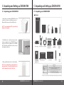
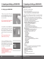
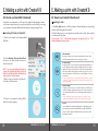
1
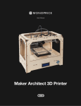
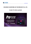
Think!
Make!
Touch!
Multiple Perfection, Desktop 3D Printer EDISON H700
USER MANUAL
This User Manual is designed to
help you start your experience with
3DISION H700. In order to achieve
great results, you will need to experiment and tinker. That’s why it’s
so crucial to take the time to learn
about your new machine. In this
User Manual, you will learn the basics of the 3DISON H700, as well as
how to unpack it safely and get it set up.
Okay. Let’s get it started.
TABLE OF CONTENTS
A. Safety Information
4
B. Welcome to 3DISON H700!
B1 About 3DISON H700
5
Specifications
B2 3DISON H700 Overview
7
C. Unpacking and setting up 3DISON H700
C1 Unpacking your 3DISON H700
8
C2 Setting up your 3DISON H700
10
D. Getting started: Filament Loading and Leveling the printing bed
D1 Filament Loading and Unloading
12
D2 Leveling the printing bed
14
E. Making a print with CreatorK 8
E1 CreatorK 8 Overview
16
E2 How to use CreatorK 8
16
F. Troubleshooting
F1 Troubleshooting (FAQ)
24
F2 Support Contact
26
Annex1. Exchanging the Extruder for the Metal Clay Printing
Installation of the Universal Extruder
27
After-treatment for Metal Print-out
30
Annex2. Extra Features
Laser Engraver
32
WiFi Camera
35
Embedded Battery
37
3DISON H700 User Manual V.1
3
A. Safety Information
B. Welcome to ∃DISON H700!
B1. About 3DISON H700
WARNING The 3DISON H700 generates high temperatures and includes moving parts that
can cause injury. Never reach inside 3DISON H700 while it is in operation.
WARNING There is a risk of shock. This product is not user serviceable.
WARNING Do not leave the 3DISON H700 unattended during operation.
WARNING Using the laser engraver requires instruction from the salesperson.
Thus, not instructed user is prohibited to use the function.
CAUTION Wearing protective glasses is recommended before using the laser engraver.
CAUTION When opening the 3DISON H700 for service, ensure that the power supply
is turned off and the cord is disconnected from the wall socket.
3DISON H700 is a desktop 3D printer based on the fused filament fabrication (FFF) method. 3DISON H700 is a world-class Desktop 3D printer boasting up to 25 micron(0.025 mm)
of superfine layer and speed of 1000mm/sec. 3DISON H700 features versatility when it
comes to wider options of materials such as metal paste as well as filament types just by
interchanging its extruder.
Besides, 3DISON H700 performs the function of cutting or carving with the laser engraver. This printer also comes with an internal WiFi Camera enabling monitoring in different
locations and embedded back-up battery in case of power failures.
※ FFF method : This method works by laying down consecutive layers of material at high
temperatures allowing the adjacent layers to cool and bond together before the next layer
is deposited.
Specifications
Printing
Method of printing
Fused Filament Fabrication (FFF)
Maximum Build Size
CAUTION Only use power supply provided with your 3DISON H700.
Printing Speed
41.6 ℓ (290mmX205mmX700mm)
40mm/sec ~ 1000mm/sec
CAUTION Do not print using materials that have not been approved by ROKIT.
Hot-end(nozzle) Size
0.4mm, 0.6mm (an 0.2mm nozzle additionally provided)
Layer Resolution
25 ~ 600micron (100~300micron recommended)
Positioning Precision
X, Y : 11micron, Z : 2.5micron
Printing Material
- Spool Type:
PLA, ABS, Nylon, Flexible-plastic, HIPS, PVA, Heat-resistant PLA,
Wood, Stone, Engineering-plastic(Thermoplastic) etc.
- Paste Type:
Metal Paste(Silver, Bronze, Copper), Chocolate Paste etc.
CAUTION The socket outlet must be located near the equipment and must be easily accessible.
KC, CE, FCC certification - 3DISON H700 is certificated by KC, CE, and FCC which
indicates that 3DISON H700 meets the requirements of customer protection on
safety, health, and environment in Korea, European, and the U.S.
4
3DISON H700 User Manual V.1
(* the speed of 1000mm/sec is possible in acceleration mode)
(*Please visit our website as often as possible and meet newly added and improved
materials which are optimized to 3D desktop printer 3DISON.
http://en.3disonprinter.com/ )
3DISON H700 User Manual V.1
5
B. Welcome to ∃DISON H700!
B. Welcome to ∃DISON H700O!
B2. 3DISON H700 Overview
Specifications
Hardware
Software
Extruder
Dual Extruder System,
Universal Extruder
Control Program
CreatorK
Shaft Thickness
X : 8mm, Y, Z : 12mm
Operating System
Windows, Mac OS X
Belt/ Pulley
Internal LED Lighting
LED for checking
operation of the
heated bed
2GT Belt / Pulley
O
O
(for checking
the working status)
Compatible File Format
STL, OBJ
O
Laser Engraver
O
Monitoring WiFi Camera
O
Embedded Battery
O
Hardware
4
6
Electrical
7
100 ~ 220v, 50/60Hz
Input
3
24v, 9.0A
Output
Inner Thermometer
5
2
Stand-alone SD card
USB Cable
Connectivity
8
9
10
11
Sound
Average Operational Noise
About 50 dBA.
Physical Dimensions
Storage Temperature
10℃ ~ 40℃
Extruder Temperature
190℃ ~ 300℃ or more
Frame Dimension
Total shipping weight
511mmX402mmX1030mm
32.5 kg
Front view
1
1
3
7
10
6
Upper view
3DISON H700 User Manual V.1
Back view
Side view
Door 2 LCD thermometer of the heated bed
Printing bed 4 Extruder 5 Roof case 6 LCD keypad
8 SD Card slot 9 USB drive port
Arrows and OK button
Power socket 11 Power switch
3DISON H700 User Manual V.1
7
C. Unpacking and Setting up ∃DISON H700
C. Unpacking and Setting up ∃DISON H700
C1. Unpacking your 3DISON H700
C1. Unpacking your 3DISON H700
Hardware
1. Open the box containing 3DISON H700. Then
you will see a foam case containing accessories.
Remove this foam case and check what is in it.
NOTE: You can download a PDF copy of this User
Manual on our website.
Printer body
2. Carefully remove a cardboard and protective
air bag covering the body of 3DISON H700, and
now you should see a glimpse of your 3DISON
H700. Take the box with the accessories out and
check what is in the box.
Power supply
PET tape
Power cable
Hex wrench
USB cable
Grease
Filament spool
(700g/1EA) x 2
SD card
Laser
engraver Kit
Tweezers
Universal
Extruder
User manual
WIFI Camera
(+LAN cable,
Installation CD)
3. Now you finally set it down on a stable surface.
NOTE: Do not discard the box and protective air
bags. Save these - they will be handy if you ever
need to transport the printer in the future.
Embedded Battery
User manual
Spanner
Spare
Nozzle
∃DISON H700
∃DISON H700 Printer Tool Kit
Filament Box
Accessories
Printer Body
PET Tape, Hex Wrench, Grease, Spanner, SD Card(4G)
Filament Spool x 2 (700g/ 1 EA )
Power Supply and Cable, USB Cable, Spare nozzle Tweezers for removal
Universal Extruder(for Paste-type Printing)
Options
Laser Kit, WIFI Camera, Embedded Battery
※ Please visit our website to purchase additional printing materials and accessories.
8
3DISON H700 User Manual V.1
3DISON H700 User Manual V.1
9
C. Unpacking and Setting up ∃DISON H700
C. Unpacking and Setting up ∃DISON H700
Display Menu Introduction
C2. Setting up your 3DISON H700
1. Create from SD : To load a file from SD Card
2. Preheat : To preheat the hot-end(nozzle)
- Extruder : by setting On/Off you can start preheating of the extruder
- Platform : by setting On/Off you can start preheating of the print bed
1. Make sure the power switch is Off. Locate the
power cord and plug it into the power input port at
the back of the 3DISON H700. Plug the power cord
into an electrical outlet.
3. Utilities : It will lead to 12 different options for hardware. You do not want to change the
settings without any specific explanation because they are only for developers or aftersales service
- Monitor mode : it shows current temperature of the extruder and printing status
- Filament loading : to put the filament into the extruder or pull it out of the extruder
- Preheat settings : to set up temperature and the printing bed
- Level Build Plate : to manually level the printing bed
- Pre-leveling : to level the printing bed before starting Auto-leveling
- Home Axes : To default the position of X, Y, Z axis
- Bot Statistics : Shows the operation time spent printing.
- Life Time: Total operation time of 3DISON H700
- Last Print: Last build time
- Filament: Total amount of filament used (in meter)
- Fil. Trip: Amount of filament used for the last build (in meter)
- Filament Odometer : Not only this shows the filament information, but also you can de
fault the trip value here.
- Life: Total amount of filament used (in meter, unable to reset)
- Trip: Amount of filament used for the last build (in meter)
- General Settings : To configure sound, LED color or etc
- Ditto Printing Off
- Override GCTemp OFF
- Pause with heat OFF
- Sound ON/OFF
- Heat LEDs ON/OFF
- LED Color :to change LED colors.
- Accelerate : To accelerate the extruder speed
- Extruders : To choose SINGLE or DOUBLE depending on 3DISON H700
- Extruder Hold ON/OFF
- HBP Installed NO
- Tool Offset Sys NEW
- Check SD Reads YES
- P-Stop Control OFF
- Profile
- Home Offsets
- Jog Mode : To control manually the location of the extruder and the build platform
* Press the 3D button to go back to the main menu
- Disable Steppers : To stop the motor.
- Enable Steppers : To start the motor.
- Blink LEDs : To make LED lamp flickering
- Calibrate Nozzles
- Restore Settings :To initialize 3DISON H700
- Eeprom
- Version Information : It shows the firmware version.
NOTE: The socket outlet must be located near the
equipment and must be easily accessible.
2. The on/off button (‘– | O’) of the 3DISON H700 is
located in the upper part on the back of the machine.
The ’O’ represents off and the ‘–’ represents on.
When the switch ON ‘–’ the 3DISON H700 is turned
on and should start up. Press the power button to
start. NOTE: It is recommended to turn off the
3DISON H700 when it is NOT in use.
3. Once you see the LCD display as shown in the
picture, load filament and then level your the printing bed for the first time. You can load or unload filament, or adjust the horizontality of the printing bed
by selecting the concerned menu Utilities.
Tip. LCD Display
Four Arrow buttons surround a central OK button.
Use the arrows to navigate through the LCD menus
OK button is to make selections.
The left arrow often allows you to go back or
cancel an action.
●
●
●
10
3DISON H700 User Manual V.1
3DISON H700 User Manual V.1
11
D. Getting started:
Filament Loading and Leveling the Printing Bed
D1. Filament Loading and Unloading
D. Getting started:
Filament Loading and Leveling the Printing Bed
D1. Filament Loading and Unloading (Continued)
When loading
When Unloading
1. Go to the LCD panel and select Utilities > Filament Loading. Select Load Right or Load Left
depending on which side you want to load the
filament. Then the extruder will start preheating.
1. To remove the filament from the extruder, select
Utilities>Filament Loading and select Unload
Right or Unload Left depending on which side
you want to remove the filament.
2. When the extruder is completely heated with
the alarm, put the filament spool into the roof case
and insert the filament into the hole in the middle
of the roof case.
2. When the extruder is completely heated with an
alarm, locate the extruder to the middle.
NOTE: Put left filament into the front hole and right
filament into back hole on the roof case.
3. After opening the front door, check to see if the
inserted filament is in, then locate the extruder to
the middle.
3. Pull the filament out of the extruder with the
spring block pressed.
4. Push the filament into the blue cap on the extruder
by pressing the spring block until you feel the motor
pulling in it. Wait until you see the filament coming
out from the extruder nozzle.
NOTE: Please make sure to keep the end of
curved filament straight before inserting.
4. Press the OK button to stop unloading.
5. Press OK button to stop loading.
12
3DISON H700 User Manual V.1
3DISON H700 User Manual V.1
13
D. Getting started:
Filament Loading and Leveling the Printing Bed
D. Getting started:
Filament Loading and Leveling the Printing Bed
D2. Leveling the Printing Bed (Continued)
D2. Leveling the Printing Bed
Leveling before 3D printing is so crucial that it can influence the quality of the print-out. If the
printing bed is too far from the extruder’s nozzles, or if one part of the bed is farther away from the
nozzles than another part, your 3D prints might not stick to the bed.
Meanwhile, if the printing bed is too close to the extruder’s nozzles, the bed can block the filament
from extruding from the nozzles. This can also scratch the printing bed and tear the PET tape on it.
When using Standard Leveling (manually adjusting)
When using Auto-Leveling
1. Place the A4 size paper first before using
Auto-leveling functions. Select Utilities > AutoLeveling in the display menu.
1. Press the power button to start to adjust the
horizontality of the printing bed. Open the front
door and put a sheet of A4 paper onto the printing
bed before manual leveling.
NOTE: The thickness of A4 size paper is about
0.1mm and this paper is used in leveling the bed
to keep 0.1mm space between the nozzle and
the printing bed.
NOTE: The thickness of A4 size paper is about
0.1mm and this paper is used in leveling the bed
to keep 0.1mm space between the nozzle and
the printing bed.
2. Select Utilities > Standard Leveling on the
display menu.
2. When the extruder comes to the center, adjust
4 round knobs while trying to pull forward the A4
paper to verify the space as the same manner as
Standard Leveling (See item 4 in page 14).
3. Level the printing bed by adjusting the round
knobs each time when the extruder reaches to
the front, rear, left, right and center in sequence.
(Press the OK button so that the extruder move to
another point.)
NOTE:
In case of using Auto-Leveling, it is okay to level
the center of the printing bed only before use
unlike Standard Leveling.
It is recommendable to use Standard Leveling
one time in 10 times of Auto-leveling, or when
physical shock occurs to the printing bed.
●
●
NOTE:
At this time, it is important that you should turn
the round knobs as same degree as possible at
the same time using both hands.
If knobs are turned to the left, the gap between
the nozzle and the printing bed will increase. If
knobs are turned to the right, the gap between
the nozzle and the printing bed will decrease.
4. Upon completion of adjusting the round knobs each time when the nozzle reaches to
the printing bed in sequence, pull forward the A4 size paper and if the A4 size paper touches
the nozzle and slides with feeling of a little bit scratching, leveling has been completed.
Press OK button to finish the leveling.
NOTE: In CreatorK, uncheck the mark in the Auto-leveling item when generating Gcode.
●
●
14
3DISON H700 User Manual V.1
3. Insert the SD Card on the top of the printer and
select the file on LCD panel. It starts to print with
auto leveling function.
NOTE: In CreatorK, check the mark in the
Auto-leveling item when generating Gcode.
3DISON H700 User Manual V.1
15
E. Making a print with CreatorK 8
E1. CreatorK 8 Overview
Rokit Inc. has developed CreatorK 8 to help its users to easily convert STL and OBJ files
into G Code, X3G format that can be 3D printed with this 3D printer.
You can always expect the best output by changing a variety of settings on CreatorK 8.
Menu Bar Overview
E. Making a print with CreatorK 8
2. Follow the directions to install the software. The
installation of Python 2.7.6 and USB driver is
automatically implemented at the same time.
※ Python : It is one of the widely used programming languages which enable the slicing program
named Skeinforge to activate.
Generating G-code
Save into SD Card
Connecting
: When you connect your computer and CreatorK8 with USB cable
Disconnecting
Build
: When you want to print out the x3g file directly through USB cable
Pause
3. Go to the Desktop and you can see the “CreatorK” generated. Once you opened CreatorK 8, select Machine > Machine Type. You should select
corresponding Machine Type of 3DISON+ single,
3DISON+ duo, 3DISON MULTI, 3DISON PRO or
3DISON H700.
4. In order to select the language displayed on this software, please refer to the below
images(it shows how to change Korean into English). Finally, close the CreatorK 8 and
restart it. Now CreatorK will be ready to use.
Generating G code to use
Laser Engraver
E2. How to use CreatorK 8
Installing CreatorK 8
1. Run “CreatorK V8 Install” setup file.
16
3DISON H700 User Manual V.1
3DISON H700 User Manual V.1
17
E. Making a print with CreatorK 8
E. Making a print with CreatorK 8
E2. How to use CreatorK 8 (Continued)
E2. How to use CreatorK 8 (Continued)
Basically, it is recommended to use SD card to save .x3g file for 3D printing for safety in
case of power outage. However, you can also print directly on your CreatorK by connecting
your computer to the printer with the USB cable without saving and using SD card.
Connecting to Printer on CreatorK 8
Generating G-code
1. Select File > Open and choose STL file you want to 3D print. Otherwise you can just drag
and drop the 3D image file into CreatorK 8.
2. When the file appears, you can adjust the size and the position of the object using the
icons below on the menu bar.
1. Connect your computer to the printer with the
USB cable.
Tip. If you push “Ctrl Z” it will undo the last function. The opposite of Ctrl Z is “Ctrl Y”
which commands reverses the undo.
Mirror function
If you want to change x, y, z’s mirror, click and put the mouse pointer on the
box. Click right mouse button, and you can adjust x, y, z mirrors.
2. Go Select Machine >Connection(Serial Port)
and choose one of the detected serial ports on
the same menu bar.
Position change
Using the 4 arrow icon, you can move the object. After clicking this button,
you can adjust the position using direction keyboards.(It moves 1mm per
click) And you can also move the position of the object using right button
of the mouse. When clicking right mouse button, you can see x, y, z and
center of the platform. You should choose center of platform every time
you print out.
NOTE : If you are using Windows 8 and want to
connect the computer and printer, please visit
Rokit Inc’s website and refer to the instruction to
install a driver to use this function.
3. After choosing your serial port, click the Connect button on the menu bar.
※ NOTE : Since 3DISON is based on a FFF(Fused Filament Fabrication) method in the 3D printer,
the object piles up in layers on the plate. Therefore, if it is not fixed upon the surface, you may not
get the result you expected.
Rotation change
Using this circle arrow icon, you can rotate the object as you wish to print
out. When clicking the right mouse button, you can see the screen below.
You can rotate the object by X, Y, Z axis or by dragging it with the left mouse
button.
※ NOTE : Depending on the rotation, the quality of objects may vary. The support is created
automatically if the tilting degree of the angle is at least 45°. So this process is very important.
4. Connect to your printer by clicking ”Build”
button to start your printing.
Rescale
You can adjust the size using this magnifying glass icon. By dragging up and
down mouse, you can rescale the object. And when you click on the platform,
you can rescale the object to the maximum size. If you enter one, the others
will change in proportion.
18
3DISON H700 User Manual V.1
3DISON H700 User Manual V.1
19
E. Making a print with CreatorK 8
E. Making a print with CreatorK 8
E2. How to use CreatorK 8 (Continued)
E2. How to use CreatorK 8 (Continued)
3. Once you finished, click on the G-code icon on the
far left to generate G-code. Then a pop-up window will
show up to save or not to save the .stl file which you
have edited in location or size etc. After this, you can
see this display.
2) Support
(Right after
removing a raft
and supports)
Tip. 3DISON’s software CreatorK 8 is based on the Skeinforge,
which has a plenty of settings. We are providing about 9
appropriate printing options so that any users can set up the
profile easily.
But, please note that you should enter each settings unless
you choose a specific printing option. (Uncheck the mark in the
Advanced Setting item.)
Full Support
Exterior Support
Raft(Base)
Following are specific explanations about the items
you should set up before generating G-code. Your
print-out’s quality and time will be affected.
1) Printing Option
There are basic profiles optimized to print out what you want conveniently.
(suggested but not required)
※ If you don’t want to use these printing option, generate your own printing
option by selecting GCode-Edit Slicing Profiles and clicking any profile and Copy.
① High Speed : 0.2 mm layer height for big-sized object
- 700 mm/sec on 3dison Pro and 3dison H700
- 300 mm/sec on 3dison Multi
② Standard : 0.2 mm layer height for mid-sized object
- 100 mm/sec on 3dison Pro and 3dison H700
- 100 mm/sec on 3dison Multi
③ High-Precision : 0.05 mm layer height for small-sized object
- 40 mm/sec on 3dison Pro and 3dison H700
- 40 mm/sec on 3dison Multi
④ Supreme-Precision : 0.025 mm layer height for small sized and smooth surface
- 40 mm/sec on 3dison Pro and 3dison H700
- 40 mm/sec on3dison Multi
※ The thinner the layer height the more the time is required to finish 3D printing
⑤ Laser : to cut 3 mm-thick acryl and 2 mm-thick plywood
⑥ Metal(Silver), ⑦ Metal (bronze), ⑧ Metal (Cooper), ⑨ Metal (Steel)
※ When generating Gcode before starting metal printing, be sure to choose the corresponding ‘printing option’ depending on materials. These settings are optimized to the material and theses are provided by the developers of ROKIT Inc.
20
None : 3DISON H700 would not build support, but only raft.
Exterior Support : Choose if there is a space between the bottom surface of the object and the plate.
Full Support : Choose if there is a space in the middle of the object.
3DISON H700 User Manual V.1
Tip. According to how you locate the
object, different shape of supports will be
printed. Minimizing supports as possible
leads to better results as well as saving
the material used for support.
(Before removing a raft and supports)
3) Use Auto Leveling You can choose auto leveling function optionally. If you want to adjust the printing bed manually, don’t check the box.
4) Advanced Settings If you check advanced setting box, you can find several setting options for printing. There are four categories in this advanced setting.
Settings
① Object Infill (%)
You can enter a number between 10 and 100 to fill inside.
Tip. It determines the density. If the density is not an important
factor, you may set it up to less than 50 to save the overall printing
time and material.
② Layer Height (mm)
You can enter a number between 0.05 and 0.3 for layer height.
Tip. The higher the layer is, the less the printing time. It is recommend-able for you to enter the number of over 0.1 mm in this item.
③ Number of Shells
You can enter a number from 0 to 3 to determine the thickness
of outer cover and it depends on the object infill settings. When
you don’t want to make a shell, you should fill 100% inside.
Tip. When you want to enter ‘0’ for shell, you should fill ‘100%’ inside.
3DISON H700 User Manual V.1
21
E. Making a print with CreatorK 8
E. Making a print with CreatorK 8
E2. How to use CreatorK 8 (Continued)
E2. How to use CreatorK 8 (Continued)
④ Feedrate (mm/s)
This shows how fast the extruder moves per second when it prints. You can choose between 20 and 1000.
The lower the speed, the less the vibration and the output has smoother surface. The speed of 80~100 is
recommended.
⑤ Travel Feedrate
This shows how fast the extruder moves per second when it does not print. The same number of feed rate
is recommended.
⑥ Print Temperature
This determines the extruder’s temperature at which the filament is melted. The temperature is variable depending on the materials. 195-215℃ for PLA, 235-250 ℃ for ABS recommended.
⑥ Heat Bed Temperature
70-80℃ for PLA, 145-150 ℃ for ABS.
Material
When you use different diameter of filaments, you should input corresponding diameters.
Extruder
It indicates nozzle’s diameter. 3DISON H700 applies 3 different nozzle diameters : 0.2mm, 0.4mm and 0.6mm. You should select corresponding diameters when using different nozzles.
Default
Click ‘Set Default Value’ if you want to change values which were changed in Advanced Settings to initial set value.
4. After setting all the options, click generate G-code
button which is at the bottom of the pop-up. And
then you can see G-code build process screen. This
process is a slicing process enabling 3DISON to 3D
print the STL 3D image.
Printing with Dual nozzle system
1. Prepare two STL or OBJ files which compose a
single object. Click G-code bar on the top of the
window. Click Merge.stl for Dual Extrusion to
merge into one g-code file.
NOTE : You CANNOT use support function in the
dual nozzle system. For two files cannot mesh with
each other if the supports are printed.
2. Choose two of each files(①, ②) you want to merge and designate the location to save.
Then create the name of the G-code file to be generated. Then click merge button. You will
see the two pop-up windows that settings must be made separately.
①
②
①
②
①
②
5. Once finished this work, SD card icon color will
change, indicating G-code has been generated successfully. And then click the SD-Card button to save
the file in the SD Card.(.x3g)
22
3DISON H700 User Manual V.1
3DISON H700 User Manual V.1
23
F. Troubleshooting and Maintenance
F. Troubleshooting and Maintenance
F1. Troubleshooting (FAQ)
F1. Troubleshooting (FAQ)
Hardware
Hardware
Q. What if the filament is not properly discharged?
A1
There are a few causes to prevent filaments from coming out well. One of the most common causes is
when is clogged. When this happens, set the extruder temperature higher than 240℃ at [Utilities] > [Preheat
Setting], and use [Preheat] function of display menu to melt the filaments accumulated inside the nozzle,
whereby the nozzle can be unclogged. (Reduce the extruder temperature again after use).
If the method mentioned above fails to solve the problem, use a hex wrench to unscrew the two bolts positioned at an upper surface of the extruder and the two bolts positioned at a lower surface of the extruder,
separate the two parts and check if filament scraps clog the nozzle hole. Next, unclog the nozzle hole using
a long unfolded clip or a smallest hex wrench provided at the time of purchase while the extruder is under a
preheated state (do the separation work while the power is turned off after preheat. Malfunction may occur if
fan separation work is performed while the extruder is under the preheat state)
A2
Malfunction may also occur when the gear extruding the filament is not properly operated. If malfunction occurs, dismantle the extruder, and remove the wastes accumulated on the gear using a brush such as
tooth brush, then the problem can be solved.
A3
It is also important to set the extruder temperature according to material. If the extruder temperature
is too high or too low, the material may hold together, or may not be properly solved to prevent a smooth
output. Be sure to check the proper temperature according to the used material.
Q. What if the printed object is generated with shrinkage?
A1
It is important to control an ambient temperature of printed object under FFF method in
which filaments are melted and stacked at a high temperature and stacked. When an ambient temperature of printed material is low, shrinkage might happen, and it may also occur if no heat exceeding a predetermined temperature is applied to the output board depending on used material. In
order to prevent shrinkage, the temperature inside the printer must be maintained at a predetermined level or the temperature of output board must be adjusted according to used material.
※ Temperature inside the printer may change depending on the season and surrounding
environments.
Software
Q.Is design also available from the dedicated 3DISON’s software (CreatorK)?
A1
The dedicated 3DISON’s software (CreatorK) is an optimized program to enable a simple
setting 3D printing whereby no design correction is allowed. Manufacturing and designing of 3D
modeling file must use 3D design program.
Q. What if the printed material is not properly stuck to the printing bed?
Q. Can MAX OS X use the dedicated 3DISON software (CreatorK)?
A1
If the printed material is not properly stuck to the output board, or if the printed material is not properly outputted, it means that there is a problem in a gap between the nozzle and the output board. If this
problem occurs, select [Utilities] > [Standard Leveling], adjust round knobs underneath the printing bed, and
properly adjust the gap between the printing bed and the nozzle. This problem can be easily solved if Auto
Leveling function of EDISON H700 is used (See page 15).
A2
The temperature of the printing bed may also be a cause preventing the printed object from being
properly attached to the printing bed, which can be solved by setting a proper temperature of heated bed
catering to the material to be used. In general, the temperature for PLA is in the range of 60℃ ~ 80℃, and the
temperature of ABS requires a bed temperature of above 110℃.
24
3DISON H700 User Manual V.1
A1
Dedicated 3DISON’s software (CreatorK) supports Window and Mac operating systems. These
operating systems can easily be installed and used.
Q. What types of 3D files are required to use the laser engraver?
A1
STL file that is identical to the existing 3D modeling file is required. However, the modeling
must be performed in such a manner that a shape to be cut be done in a linear format of 1mm
width, and a thickness to be cut be three times thicker. The modeled STL file can be easily used by
selecting a laser mode on Creator K.
3DISON H700 User Manual V.1
25
F. Troubleshooting and Maintenance
Annex1. Exchanging the Extruder for the Metal Clay Printing
F1. Troubleshooting (FAQ)
3DSION Metal Clay Printing
Material
Q. Is it possible to use material purchased from other companies?
This metal kit comes with the printer. Final product is made by the process of 3D printing
the metal clay through the nozzle and then firing the metal clay. For this interesting 3D
printing, you should first open the metal kit.
What’s in the METAL KIT
A1
We recommend that you use a certified genuine filament in order to guarantee a stable output and product protection. You might not be able to get after-sales service benefits if non-genuine
filament is used.
Universal Extruder
Motor Cable
Syringe
Q. Is it possible to print in filament format using a metal material?
A1
The metal material is provided in a paste type in a dedicated cartridge, not in the filament
type. Various materials may be outputted including a metal material and chocolate by replacing an
extruder part from which material is extruded.
F2. Contract Support
For service assistance after purchase, please contact us to the phone number or email below.
T : +82-2-867-0182
F : +82-2-865-0182
Email : [email protected]
Extruder Stopper
Stainless Stell Mrush
Ceramic Tile
METAL KIT
1 Universal Extruder
(it consists of syringe in which metal clay is contained and an extruder which discharges
required quantity)
1 Ceramic tile (used as print bed)
1 Motor cable
1 Stainless steel brush (for processing after firing)
1 Nozzle
1 Extended stopper (for the limited switch)
※ Visit our website to purchase additional accessories (metal clay syringes, coal
crumbs, cube box etc.) and get further information on metal clay 3D printing.
- Metal clay syringes : Silver/ Bronze/ Copper/ Steel
- Coal crumbs (carbon for preventing the metal binder from meeting with Oxygen)
- Cube box (for containing coal crumbs with the metal clay printout when firing)
Please refer to our website for more information and latest news and questions regarding
our products on our website. (http://en.3disonprinter.com/)
Mini Electric Kiln
26
3DISON H700 User Manual V.1
3DISON H700 User Manual V.1
Cube box
Coal crumbs
27
Annex1. Exchanging the Extruder for the Metal Clay Printing
Annex1. Exchanging the Extruder for the Metal Clay Printing
3DSION Metal Clay Printing
3DSION Metal Clay Printing
1. How to install and use extruder
⑤ Attach the Extended Stopper to the lower part of Z
axis to make the printing bed stop at the fixed distance
for metal printing. (Use stopper in the image1 for 3DISON
Multi and use stopper in the image2 for 3DISON H700.
They differ in length.)
① First, open the box and take the metal extruder
out of the box. Release 2 bolts on the base part and
separate the extruder installed in 3DISON H700.
Pull all of the cables out of the PCB and keep the
bunch of nozzles separately.
② Install the metal extruder by fastening the bolts
with a hex wrench. Connect supplied motor cables
to the motor and PCB.
Image 2
Image 1
③ Take the syringe out of the box and insert the
yellow nozzle in the head of the syringe. Insert the
syringe in the installing part of the extruder and
cover it.
⑥ Put the ceramic tile on the bed after save x3g. file
in the SD card. Select file to print and start printing.
NOTE : In case the thickness of layer is out of the
range 0.7~1mm when printing, adjust the thickness
by re-tuning the leveling. Or tighten the bolt (small
set screw in the gear) using a supplied hex wrench
makes thicker layer and releasing the bolt makes
thinner layer.
NOTE : Check if discharging goes well by pressing
the piston to take about 4~5cm of clay.
④ Turn the biggest gear to the front as shown in the
image so that the belt will be as tight aspossible.
Steel
28
3DISON H700 User Manual V.1
3DISON H700 User Manual V.1
Bronze
Silver
Copper
29
Annex1. Exchanging the Extruder for the Metal Clay Printing
Annex1. Exchanging the Extruder for the Metal Clay Printing
3DSION Metal Clay Printing
3DSION Metal Clay Printing
2. How to do a after-treatment for metal print-out : Firing method after 3D printing
Sample should be processed in after-treatment process of drying and firing when metal
paste is still in clay condition after being printed. Process for after-treatment depending on
material is as follows;
1) Silver paste
① Take out printed clay with the tile and dry it for 24 hours by natural drying or dry it by
warming for at least 1 hour using hair dryer or dry it by heating in the mini toaster oven for
10 minutes in 200°C. Print-out which has been completely dried and cooled down can be
detached from the tile easily.
NOTE : Be careful that print-out which is not completely dry, might be difficult to get complete firing and liable to crumble.
2) Copper/Bronze/Steel paste
① Take out output clay with the tile and dry it for 24 hours by natural drying or dry it by
warming for at least 1 hour using a dryer. Print-out has been completely dried can be
detached from the tile easily.
② Prepare firing for dried sample using cube and carbon which are optional items. Build
up about 3cm of carbon on the cube and put the sample on it and bury the sample entirely
by pouring carbon on the sample as much as possible and then close the cover.
<Comparison of set temperature and firing time by material> Copper
Bronze
Steel
Set temperature: 980°C
Firing time: 4 hours total
Set temperature:
130°C>>843°C Firing time: 9 hours total
Set temperature:
778°>>990°C
Firing time: 1 hour in 778°C,
additional firing in 990°C for
2 hours
② Put the dried print-out in the electric kiln and set temperature at 780°C and fire it for 10
minutes. Then silver clay changes into fine silver. Switch off the kiln and open the door to
cool down the heat enough before taking the print-out out of the kiln.
* After set at 130°C,
increase by 130°C per an
hour up to 843°C. I.E.
130°C>260°C>390°
C>520°C>650°C>780°C>843°C
NOTE : Mini electric kiln which ROKIT Inc. provides or any electric kiln which can be heated
up to 980°C can be used but quality of fired output may vary depending on the kiln.
NOTE : Use tongs or wear gloves when take the sample out of the kiln to avoid scald.
③ As the surface of the print-out taken out of the kiln has binder powder on it, brush off
the surface using stainless steel brush provided in the kit box and silvery product will be
completed.
NOTE : Cube and carbon are recyclable (only the part which has not changed into white
ash by oxidation).
※ TIP
NOTE : Brush thoroughly every corner for completion.
30
③ Upon completion of firing, switch off the kiln and open the door to cool down the heat
enough. If the heat cools down to room temperature, finish work by taking the sample out
of the cube and brushing the sample using stainless steel brush.
Be careful of scald when use toast oven or kiln and especially, in case the output has been
fired in kiln, cool the output enough by opening the door at least an hour before take the
printed object out of the kiln.
When you print in the tile after dry in toast oven, the output will not be separated easily unless
you cool it enough so cool it for at least 30 minutes before you separate the output and then
put it on wire mesh and put in the kiln.
3DISON H700 User Manual V.1
3DISON H700 User Manual V.1
31
Annex2. Extra Features
Annex2. Extra Features
Laser Engraver
Laser Engraver
(Laser Engraver / WiFi Camera / Embedded Battery)
With this laser engraver, it is possible to cut off a thin wood or acrylic board what you design
in 3D modeling tool. Before you start installing using this laser engraver, please make sure to
be EXTRA PRECAUTIOUS when handling the laser engraver.
(Laser Engraver / WiFi Camera / Embedded Battery)
⑤ Insert the laser nozzle bar into the laser mount
and fix it.
⑥ Switch on power after connecting the laser
connector to the PCB connector.
(This symbol stands for warning in using lasers.)
1. How to install
① Power must be off before installation for your
safety.
WARNING : Do NOT disassemble the laser mounted in the aluminum socket. This is designed for user’s safety. A laser is a light source that can be dangerous to people exposed
to it. Even low power lasers can be hazardous to a person’s eyesight.
NOTE : Before exchanging the existing extruder, please make sure that the hot end reaches
the printing bed.
② Separate the existing extruder connector and
PCB connector.
1. How to use
③ Release connecting two bolts between the nozzle mount and the existing extruder using a hex
wrench and then separate.
① Put the plywood or acrylic plate to cut on the
printing bed of the printer.
② Perform 3D modeling for the shape to cut in line
of 0.4mm width and store the 3D modeling in STL
file format.
The height of the object on 3D modeling should be
1 mm.
④ Assemble the laser mount in the right direction
on the separated nozzle mount and fix it using a
connecting bolt.
NOTE : In using this laser engraver, it is possible to
cut a maximum 3 mm-high acryl and a maximum
2 mm-high plywood.
32
3DISON H700 User Manual V.1
3DISON H700 User Manual V.1
33
Annex2. Extra Features
Annex2. Extra Features
Laser Engraver
WiFi Camera
(Laser Engraver / WiFi Camera / Embedded Battery)
(Laser Engraver / WiFi Camera / Embedded Battery)
It is now now more convenient to check on the printing progress with the Wifi camera. You
can promptly take action to solve any kind of trouble using smart phone application (VS Cam).
Following is the instruction on how to utilize WiFi Camera monitoring through your mobile
or computer.
③ Import worked .stl file after execute CreatorK 8
and click G-code generating button on the top.
1. Connecting to your mobile
① Connect the Internet router to WIFI Camera via
LAN cable. About one minute of booting time is
required.
④ Select Laser Mode in Printing Option and click
Generate Gcode.
② Download “VsCam” app using a mobile phone.
(Android and IOS are supportable)
⑤ Transfer the generated Gcode to another Gcode
optimized to use the laser function by clicking
Laser Icon.
③ Enter [Add Camera] after execution of ‘VsCam
app’ to input UID number attached to a rear surface
of body, and input an initial PIN (personal identification number) 888888.
⑥ Save the generated Gcode for laser use in the
format of x3g in SD Card. Then directly insert it in
the printer and turn on the printer.
④ Click an added camera to set IPCAM for wireless
connect-ion.
[Camera settings] > [WIFI settings] > [WIFI Manager] > select a currently used wireless SSID > finish by inputting PIN.
NOTE : Go to Utilities < Laser Blinking to check if
laser works properly or not. This blinking lasts for 5
seconds.
NOTE : Before using the laser engraver, make sure
that ‘Standard Leveling’ has been completed.
(refer to page 13)
34
3DISON H700 User Manual V.1
3DISON H700 User Manual V.1
35
Annex2. Extra Features
Annex2. Extra Features
WiFi Camera
WiFi Camera
(Laser Engraver / WiFi Camera / Embedded Battery)
⑤ You can check an image in real time by clicking
the added camara to ‘VsCam app’.
(Laser Engraver / WiFi Camera / Embedded Battery)
④ Connect the camera to the program by double
clicking IP Camera on the right. Once you have
checked the connection, Click a button at right of
mouse to select [Camera Options].
NOTE :
● The wireless connection may generate a
problem if the Internet router SSID (wireless
network name) is inputted with special
characters, Hangul and/or word spacing,
so you must check the SSID when connecting.
PIN may be changed after installation.
About two minutes of booting time is required after removal of LAN cable connected
to the camera.
● When the wireless SSID is not set with PIN, simply click OK button without inputting
the PIN.
●
●
⑤ Click [Set WIFI]>[Search Signals] on the option
screen. Select currently used wireless SSID > click
[Set] button > click [OK] button after inputting PIN.
Once the message saying to disconnect LAN Cable
appears, disconnect.
2. Connecting to your computer
① Connect the Internet router to WIFI Camera via
LAN cable. About one minute of booting time is
required.
NOTE :
The wireless connection may generate a problem if the Internet router SSID (wireless network name) is inputted with special characters, Hangul and/or word spacing, and therefore,
it is imperative that SSID be checked when connecting.
● PIN may be changed after installation.
● About two minutes of booting time is required after removal of LAN cable connected to the
camera.
● When the wireless SSID is not set with PIN, simply click OK button without inputting the PIN.
●
② Install the IP Camera Super Client by executing
the CD enclosed in the product.
Embedded Battery
Embedded battery prevents emergent situation which is unexpected stopping supply of
electricity during printing. Continuous printing without stopping is possible even if
the power cord is pulled off by mistake or in case of sudden blackout.
③ Enter Add Camera after execution of the program to input UID number attached to a rear surface of body, and input an initial PIN (personal identification number) 888888.
36
3DISON H700 User Manual V.1
Output Power
Maximum Run Time
Battery Type
22.2 Vdc / 5200 mAh
About 40 min. Lithium
3DISON H700 User Manual V.1
37
Memo
38
Memo
3DISON H700 User Manual V.1
Multiple Perfection
Desktop 3D Printer
E DISON H700
E DISON 3D PRINTER c ROKIT Inc.
B-1106 Kabul Great Valley 60-5
Gasan-dong Geumcheon-gu Seoul Korea
http://en.3disonprinter.com/
T. 02-867-0182
F. 02-865-0182
E-mail. [email protected]