1
Topology User Manual
Kittel Austvoll
This version of the manual applies to NEST 1.9.r8375 and later.
Contents
1
Introduction
The topology module is used to create connections between layers of nodes. Creating a connection between two layers of nodes consists of two main processes:
• Creating your layers
• Connecting the layers
The module can either be accessed through the NEST SLI executable or through
the PyNEST interface. In this userguide we’re using the PyNEST interface.
Before using the module you need to import it in addition to the nest module
itself. We import nest.topology here under the short name topo and will use
that throughout this manual. Thus, all commands from the Topology module
need to be prefixed with topo., while commands from nest proper are prefixed
with nest..
import nest
import nest.topology as topo
PS! More information about how to use the different commands included in the
module can be found at the NEST helpdesk.
PPS! Please send bugs and other feedback to nest user@nest-initiative.
org!
2
Creating your layers
Layers are created with the command CreateLayer. The CreateLayer command
adds a new node of the type layer or the type layer unrestricted to your simulation network. The difference between the two layer types is that the unrestricted
layer can place its nodes freely in space while the regular layer is restricted to a
fixed node grid. The layer (or unrestricted layer) model inherit from the subnet
model, making the layer node both a subnet and a layer.
1
Being a subnet all regular node and subnet commands can be used on the
layer node. SetStatus, GetStatus and PrintNetwork are some examples of subnet
or node commands that can be usefull when working with layers.
The CreateLayer command accepts a dictionary as its sole input argument.
We’ll first go through how to set up this dictionary to create a layer node, then
how to set up this dictionary to create a layer unrestricted node.
2.1
Creating a fixed grid layer
The most basic fixed grid layer dictionary contains the parameters:
• rows - number of nodes along the y-dimension of the layer
• columns - number of nodes along the x-dimension of the layer
• elements - node models used in the layer
• extent - the spatial dimensions (width and height) of the layer
All these parameters should in most cases be included when creating a fixed
grid layer. The extent parameter takes on the default values [1.0, 1.0] if nothing
else is specified.
According to these input parameters the layer subnodes are distributed on
a fixed grid, where the rightmost node is placed on the rightmost edge, the
leftmost node is placed on the leftmost edge and so on, and where the other
nodes are distributed uniformly throught the rest of the space.
2.2
Setting up the elements parameter
Each position in the layer corresponds to a node in the layer node vector. The
nodes in the layer node vector can either be single nodes or subnets. A single
node is created by passing the name of the node to the elements parameter
"elements": "iaf_neuron"
A subnet of nodes can be created by enclosing several neuron types in brackets.
Each bracket indicates a subnet.
# Create a subnet of nodes consisting of a single iaf_psc_alpha
# node and a wrapped subnet of two more iaf_neurons.
"elements": [["iaf_neuron", 2], "iaf_psc_alpha"]
The single node or the subnet of nodes created with the elements parameter
will never occupy more than one place in the layer node vector no matter how
many subnets that are wrapped within one another.
The elements parameter adds a third dimension to the 2-dimensional layer.
Each node in the elements parameter is associated with a specific depth. The
nodes within the topmost subnet in the elements structure is given a depth equal
2
to their local id within that subnet. If only a single neuron exists at the topmost
elements level it is given the depth 1. In the description of the ConnectLayer
command you’ll see how this third dimension can be used to create connection
patterns in a 3D layer structure.
For SLI users: A subnet of nodes can be created by passing a SLI procedure
to the elements parameter. The nodes created with the SLI procedure will
automatically be placed inside a main element subnet. The elements procedure
should keep the size of the SLI stack unchanged!
/elements {/iaf_neuron 2 Create ;}
Example: Creating a 3 by 4 layer of iaf-neurons
layer = topo.CreateLayer({"rows": 3,
"columns": 4,
"extent": [1.0, 1.0],
"elements": "iaf_neuron"})
2.3
Studying the layer with the PrintNetwork command
The PrintNetwork command can help us to get a better understanding of the
layer node hierarchy. Observe how the 2D layer uses a 1D node vector to store
its nodes. The layer uses column wise folding to convert between the 1D node
vector and the 2D space.
Example: Viewing the layout of a 3 by 4 layer of iaf-neurons
nest.PrintNetwork(1, layer)
+-[1] layer dim=[12]
|
+-[1]...[12] iaf_neuron
2.4
Wrapping the layer edges
The layer can be wrapped or cut-off (truncated) at the edges. The edge is by
default cut-off. By setting the dictionary parameter edge wrap to true the edges
will be wrapped instead.
nest.SetStatus(layer, {"edge_wrap": True})
2.5
Changing the 2D position of the layer
The previously introduced extent parameter together with the center parameters decide the position of the layer in the 2D space. The edges of the layer can
be found by taking the position of the center and adding or subtracting half of
the extent distance. The layer center is by default set to (0.0, 0.0). The layer
nodes are distributed uniformly throughout this space.
3
nest.SetStatus(layer, {"center": [0.0, 0.0]})
2.6
A complete fixed grid layer dictionary
topo.CreateLayer({"rows": 3,
"columns": 4,
"extent": [1.0, 1.0],
"center": [0.5, -1.4],
"elements": ["iaf_neuron", "iaf_psc_alpha"],
"edge_wrap": True})
2.7
The unrestricted layer
The unrestricted layer is very similar to the fixed grid layer. The only exception
is that the unrestricted layer nodes can be placed freely in the space that the
layer occupies. The nodes are placed with the positions dictionary parameter.
The positions parameter is an array that contains information about the xand y-coordinates of the layer nodes. Each element in the array corresponds to
a node in the layer node vector.
The node positions have to be within the area defined by the extent and
center parameters!
The layer nodes can either be single neurons or subnets of neurons.
Example: Creating a layer consisting of three nodes at the positions
(-0.5, 0.3), (0.0, 0.4) and (0.5, -0.2)
topo.CreateLayer({"extent": [1.0, 1.0],
"elements": "iaf_psc_alpha",
"positions": [[-0.5, 0.3], [0.0, 0.4], [0.5, -0.2]]})
For advanced users: The unrestricted layer uses a quadtree structure to
organize its nodes. The quadtree structure divides the space occupied by the
layer into different regions of nodes. The number of nodes allowed in each region
is decided by a predefined constant variable. Advanced users or developers can
manipulate this variable by adding the quadrant max nodes variable to the layer
dictionary. Most users don’t need to change this variable!
Example: Changing the layout of the quadtree structure
nest.SetStatus(layer, {"quadrant_max_nodes": 100})
2.8
When to use a fixed grid layer and when to use an
unrestricted layer
In many situations the choice of layer type will be decided by the nature of the
layer connection desired. However in some cases the same network could be
4
connected with both a fixed grid and an unrestricted layer. In that case it is
your choice which type of layer you want to use. In general a fixed grid layer is
faster than an unrestricted layers for most connection regions.
3
Connecting your layers
Once we’ve created our layers we can create connections between them. In the
topology module connections between layers are created with the ConnectLayer
command. Connections are always created between two layers at a time (or
between a layer and itself). The connections are created by specifiying which
kind of connection pattern we wish to create, and then iterate through one of
the layers and create this connection pattern for each node in that layer. In
most cases the iterating node will connect to a region directly below it in the
2D space. To find out which position this corresponds to in the connecting layer
the extent and center layer parameters have to be taken into account.
The ConnectLayer command accepts the GIDs of two layers and a special
connection dictionary describing the nature of the connection as input.
topo.ConnectLayer(source_gid, target_gid, dictionary)
The first GID passed to the command is the source layer of the connection
(the layer that emits the neural spikes). The second GID is a reference to the
target layer.
In the following sections we’ll see how the connection dictionary is created.
3.1
The connection type
The connection type parameter can be specified as convergent (previously receptive field) or divergent (perviously projective field). A convergent connection
is a connection between a group (or region) of source nodes and a single target
node. A divergent connection is a connection between a single source node and
a group (or region) of target nodes.
dict = {"connection_type": "divergent",
# other parameters
}
3.2
The synapse type
The synapse model used in the connections can be set with the synapse model
parameter. If no synapse model is set the /static synapse model will be used.
dict = {"connection_type": "divergent",
"synapse_model": "tsodyks_synapse",
# other parameters
}
5
3.3
Defining the region from which to pick connection
nodes
The region (or group) which we will pick nodes from is defined by the mask
parameter. The mask defines a region in a 2D space (where the layers reside)
from which to pick nodes from. The region can be defined as a rectangular,
circular or a doughnut parameter.
The rectangular, the circular and the doughnut parameters are all dictionaries. The rectangular dictionary contains information about the lower left
and upper right corner of the mask region. The circular dictionary contains
information about the radius of the mask region. The doughnut dictionary is a
special circular region where an inner radius and an outer radius is defined.
The position of the mask is given relative to the position of the calling node
in the iterating layer. As an example we can look at a convergent connection
between a target node at position (0.3, -0.1) connecting to a region in a corresponding source layer. The region is specified as rectangular with an lower left
corner at (-0.1, -0.1) and a upper right corner at (0.1, 0.1). The modified region
(relative to the target node) for the source layer will then be a square having
an lower left corner at (0.2, -0.2) and a upper right corner at (0.4, 0.0).
Example: Creating a rectangular mask region
dict = {"connection_type": "divergent",
"mask": {"rectangular": {"lower_left": [-0.3, -0.25],
"upper_right": [0.3, 0.25]}}}
Example: Creating a circular mask region
dict = {"connection_type": "divergent",
"mask": {"circular": {"radius": 0.3}}}
Example: Creating a doughnut mask region
dict = {"connection_type": "divergent",
"mask": {"doughnut": {"inner_radius": 0.1,
"outer_radius": 0.4}}}
Both the connection type and the mask parameter are mandatory in a connection dictionary.
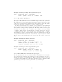
3.4
Setting the weights, delays and kernel of the mask
region
Connections initialised from different positions within the mask region can be
given different weights, delays and kernel values. The kernel parameter is a
special parameter that decides the likelihood of creating a specific connection
within the region. These parameters can either be given as constant values
6
or they can be calculated based upon the distance between the different mask
positions and the mask center. The following functions can be used to generate
values for these parameters.
• gaussian: c + p center ∗ e−(distance−mean)
2
/(2∗sigma2 )
• gaussian2D: c + p center ∗
−(
e
(x−mean x)2
sigma x2
+
(y−mean y)2
sigma y 2
−
2∗(x−mean x)∗(y−mean y)∗rho
)/(2∗(1−rho2 ))
sigma x∗sigma y
• linear: a ∗ distance + c
• exponential: c + a ∗ e−distance/tau
• uniform: [min, max] - random number
In addition the following parameters can be added to any of the functions:
• min - the minimum value that the function will return
• max - the maximum value that the function will return
• cutoff - the function will return 0 if it has a value less than the cutoff
value
• cutoff distance - the function will return 0 if the distance is more than the
set cutoff distance
• anchor - array with new center of parameters region
Example: Three different ways to set up the weights, delays and
probabilities parameters
dict = {"connection_type": "divergent",
"mask": {"circular": {"radius": 0.3}},
"delays": 1.3,
"weights": {"gaussian": {"sigma": 1.5, "p_center": 2.0,
"c": 1.0, "mean": 0.1}},
"kernel": {"linear": {"a": -0.5, "c": 1.0,
"min": 0.4, "max": 0.9}}}
Note for developers and advanced users Other distribution functions can
easily be added to the list of already existing functions.
3.4.1
Combining different parameter functions
Advanced users can combine the different parameter functions to create even
more complex connection patterns.
7
Example: Using a combination of different parameter objects
dict = {"connection_type": "divergent",
"mask": {"circular": {"radius": 0.3}},
"kernel": {"combination": [{"gaussian": {"sigma": 0.3,
"anchor": [0.3, 0.3],
"cutoff": 0.4}},
{"gaussian": {"sigma": 0.3,
"anchor": [-0.3, -0.3],
"cutoff_distance": 0.7}}]}}
3.5
Creating 3D connections with the topology module
With the help of the layer elements parameter 3D connections can be created
with the topology module. In contrast to the 2D connections which are spatially
dependent, the 3D connections are dependent upon node depth and node type.
The 3D connection pattern is set in the sources and targets parameter dictionaries. The sources parameter applies to the source layer, the targets parameter
applies to the target layer.
These dictionaries can contain the parameters model and lid. The model
parameter decides which model type that is used in the connection. The lid
decides which depth we should pick nodes from. Only one model type or one
depth can be specified for each call to ConnectLayer. If these parameters are
omitted all model types and all depths are connected to.
By wrapping subnets within subnets in the depth column many nodes can
be placed at the same depth in the layer. By using the CopyModel command
to create our own model types we can create our own model labels used with
this connection parameter.
Note to developers: If CopyModel is on its way out of NEST this command
has to be replaced with the new command.
Example: Only connecting to excitatory nodes at depth 2
# Create two neuron types
nest.CopyModel("iaf_neuron", "my_excitatory")
nest.CopyModel("iaf_neuron", "my_inhibitory")
# Create a single layer
dict = {"rows": 3,
"columns": 4,
"extent": [1.0, 1.0],
"elements": ["my_excitatory", ["my_inhibitory", "my_excitatory"]]}
layer = topo.CreateLayer(dict)
8
# Connect layer to itself
dict = {"connection_type": "divergent",
"mask": {"circular": {"radius": 0.1}},
"targets": {"lid": 2,
"model": "my_excitatory"}}
topo.ConnectLayer(layer, layer, dict)
3.6
Limiting the number of synapses per node
In the topology module the connection type parameter is particularly important when used together with the number of connections parameter. The number of connections parameter limits the maximum number of connections that
are allowed for each source (for convergent connection) or target (for divergent
connection) node. If used correctly this parameter would create a source layer
where all the nodes have the same number of synapses (for divergent connection), or a target layer where all the nodes receive the same number of input
synapses (for convergent connection).
Whether to allow autapses (connections to oneself) and multapses (many
identical connections) can also be set together with this parameter. The allow autapses and allow multapses parameters are by default set to true. PS!
The allow autapses parameter doesn’t have an effect when used independently
of the number of connections parameter.
Example: Limiting the number of synapses per target node to 100
unique synapses
dict = {"connection_type": "divergent",
"mask": {"doughnut": {"inner_radius": 0.1,
"outer_radius": 0.3}},
"number_of_connections": 100,
"allow_multapses": False}
3.7
Creating a fixed grid connection dictionary
All the features of the unrestricted layer connection dictionary are valid for fixed
grid connection dictionaries. In addition the fixed grid connection dictionary
includes some extra optional parameters.
The fixed grid layer includes an extra mask region parameter. Instead of
defining the rectangular mask parameter in terms of continuous spatial distances the rectangular mask can be defined in terms of discrete row and column
distances. The row and column distances are given with respect to the node
resolution of the layer which the mask is attached to. Using such a mask region
speeds up the connection process in most cases.
9
Example: Creating a simple fixed grid mask region
dict = {"connection_type": "convergent",
"mask": {"grid": {"rows": 2, "columns": 3}}}
3.7.1
The anchor parameter
The center of the mask grid region is by default set in the upper left node of the
grid region. This center can be moved with the help of the anchor parameter.
The mask grid row and column values starts with [0, 0] in the upper left corner
of the region, and increases downwards and to the right in the grid. The anchor
is given as a dictionary containing a row and a column position.
For fixed grid layers there also exists an anchor parameter for the individual
layers in the connection. The layer anchor helps in further re-positioning of the
layer without altering the layer parameters. The layer anchors can be given
in terms of row/column or x/y coordinates. In contrast to the row/column
coordinates, which increase downwards and to the right in the space, the x/y
coordinates increases as we move upwards and to the right in the coordinate
system (like we’re used to). If the layers are given row/column anchor points all
other spatial information such as the extent and the center are ignored. In this
case the layer is automatically given the extent [1.0, 1.0] and the center [0.0,
0.0].
Example: Adding the anchor parameter
dict = {"connection_type": "divergent",
"mask": {"grid": {"rows": 2, "columns": 3}},
"anchor": {"row": 2, "column": -1},
"sources": {"anchor": {"x": 0.3, "y": -0.5}}}
Example: Creating a centered grid mask region
dict = {"connection_type": "divergent",
"mask": {"grid": {"rows": 9, "columns": 7},
"anchor": {"row": 5, "column": 4}}}
3.7.2
Other differences between the layer types
The fixed grid layer allows for an additional kind of initialisation of the weights,
delays and kernel parameters. For this layer type the parameters can also be
initialised as an array of decimal numbers. Where each array element correspond
to a position in the mask region. The array elements are given columnwise. This
parameter type can only be used together with a grid mask region.
10
Example: Initialising the weights parameter with an array of decimal
values
dict = {"connection_type": "convergent",
"mask": {"grid": {"rows": 2, "columns": 3}},
"weights": [0.5, 0.6, 0.3, 0.2, 0.4, 0.2]}
4
4.1
Other commands
GetElement
The GetElement command can be used to retrieve a node at a specified layer
position in a fixed grid layer. The position is given on the format [column row].
The command only accepts fixed grid layers.
layer = topo.CreateLayer({"rows": 5,
"columns": 4,
"extent": [1.0, 1.0],
"elements": "iaf_neuron"})
# Retrieve node at column 2 and row 3
print nest.GetElement(layer, [2, 3])
4.2
GetPosition
The GetPosition command retrieves the position of a specific node. The position
is returned on the format [x, y].
layer = topo.CreateLayer({"rows": 5,
"columns": 4,
"extent": [1.0, 1.0],
"elements": "iaf_neuron"})
print nest.GetPosition([nest.GetLeaves(layer)[0][2]])
4.3
GetRelativeDistance
This command returns the spatial distance between two nodes. The wrapped
distance is returned if edge wrapping is used.
layer = topo.CreateLayer({"rows": 5,
"columns": 4,
"extent": [1.0, 1.0],
"elements": "iaf_neuron"})
node_a = [nest.GetLeaves(layer)[0][2]]
node_b = [nest.GetLeaves(layer)[0][3]]
11
print topo.GetRelativeDistance(node_a, node_b)
4.4
LayerGidPositionMap
The command prints a list of the layer nodes and their corresponding positions.
layer = topo.CreateLayer({"rows": 5,
"columns": 4,
"extent": [1.0, 1.0],
"elements": "iaf_neuron"})
topo.LayerGidPositionMap(layer, ’out.txt’)
4.5
PrintLayerConnections
Prints a list of connections for a layer together with the connection weights,
delays and the distances between the source and target nodes.
##Create and connect layers here
# ...
# ...
topo.PrintLayerConnections(layer, ’static_synapse’, ’out.txt’)
5
Using MPI with the topology module
The topology module can easily be used on MPI systems. The efficiency of the
module on the MPI system various according to the connection specifications.
If we’re using the convergent connection type the connection efficiency scales
linearly with the increase in processor power. The divergent connection type is
not that well suited for use on MPI systems and offers little efficiency increase
despite the increase in overall processing power.
Note to developers When using the convergent option the target node can
be identified early in the connection process and the process aborted if the node
isn’t local. For the divergent option the target node is identified at the very end
of the connection process and this approach thus leads to little or no efficiency
increase.
6
Using the topology module from the NEST/SLI
executable
The PyNEST topology functions are designed so as to map directly to the SLI
NEST executable functions. There are however a few exceptions to this.
12
The elements parameter: From SLI this parameter can only be initialised
as either a single model name or as a procedure. Array of modelnames are not
allowed.
Passing filenames: Topology functions that request a filename in PyNEST
would in most cases ask for a filestream in SLI.
Literals: Modelnames used as dictionary parameters that are passed as strings
in PyNEST are passed as literals in SLI.
7
7.1
Case studies
A gaussian distributed network
In this case study we’ll reconstruct the network described in the article Activity
dynamics and propagation of synchronous spiking in locally connected random
networks by Mehring et al. (Biological Cybernetics, 88, 395-408, 2003). You
probably have to scale down this network if you want to recreate it on your own
personal computer.
7.1.1
Creating our layers
The network consists of a single layer of excitatory and inhibitory iaf-neurons
connected to it self. Because of density differences in the distribution of the two
neuron types we’ll create a separate layer for the each neuron type.
The excitatory layer consists of 90.000 iaf-neurons placed on a fixed square
grid (300 by 300 nodes). The layer has a width of 2 mm and a height of 2 mm.
We’ll use mm as the unit of choice in our layer. The layer is wrapped at the
edges.
Excitatory layer dictionary
excitatory_dict = {"rows": 300,
"columns": 300,
"extent": [2.0, 2.0],
"elements": "iaf_neuron",
"edge_wrap": True}
The inhibitory layer consists of 22500 iaf-neurons with the same layer dimensions.
Inhibitory layer dictionary
inhibitory_dict = {"rows": 150,
"columns": 150,
"extent": [2.0, 2.0],
13
"center": [0.0, 0.0],
"elements": "iaf_neuron",
"edge_wrap": True}
After creating the layer dictionaries the two layers can be created.
Creating the layers
exc = topo.CreateLayer(excitatory_dict)
inh = topo.CreateLayer(inhibitory_dict)
You might be interested in replacing the iaf-neuron model type with a model
of your own. Or create a SLI script to go through and modify the iaf-neurons
to the nature used in the article. In this case study we’re only interested in the
connection network so we’ll skip this part.
7.1.2
Connecting the layers
Next we have to create the connection dictionaries. We’ll create one dictionary
for the excitatory neurons and one for the inhibitory neurons. We want to create
a network were each neuron receives a fixed set of inputs (11250 (9000 excitatory,
and 2250 inhibitory)). So we’ll set the connection type to receptive field connect,
and the maximum number of connections to 9000 for the excitatory dictionary
and 2250 for the inhibitory dictionary. We’ll allow multapses and autapses.
The synaptic delay is set to 1.5 ms. The weight of the signals coming from
inhibitory neurons should be four times larger than the signals coming from
excitatory neuron. We’ll set the excitatory mask weight to the arbitrary value
1.0 and the corresponding inhibitory mask weight to 4.0.
The probability of connecting two nodes is dependent upon distance and is
described by a gaussian function with a standard deviation of 0.3. The size of
the mask region is not described in the article. So we’ll set this to an arbitrary
large number. The connection process will be much faster by decreasing this
number. The connecting nodes are drawn at random from this mask region.
After finding a pair of nodes that we want to connect a random number is
drawn, if this random number is lower than the probability of connection then
the connection is created, otherwise the process is repeated.
The connection dictionaries
exc_par = {"connection_type": "convergent",
## We’ll use a circular mask with a
## radius of 1.8.
## The validity of this mask size
## has to be discussed.
"mask": {"circular": {"radius": 1.8}},
"weights": 1.0,
"delays": 1.5,
14
"kernel": {"gaussian": {"sigma": 0.3,
"p_center": 1.3}},
"allow_autapses": True,
"allow_multapses": True,
"number_of_connections": 9000}
inh_par = {"connection_type": "convergent",
"mask": {"circular": {"radius": 1.8}},
"weights": 4.0, # the weight of inhibitory connections are
# four times as high as excitatory.
"delays": 1.5,
"kernel": {"gaussian": {"sigma": 0.3, "p_center": 1.3}},
"allow_autapses": True,
"allow_multapses": True,
"number_of_connections": 2250}
Connecting the layers
topo.ConnectLayer(exc,
topo.ConnectLayer(exc,
topo.ConnectLayer(inh,
topo.ConnectLayer(inh,
7.1.3
exc,
inh,
inh,
exc,
exc_par)
exc_par)
inh_par)
inh_par)
External input
The layer should also receive input from an external poisson generator. We’ll
connect this generator with regular connection functions. The generator needs
to be initialised properly.
pois = nest.Create("poisson_generator")
nest.DivergentConnect(pois, nest.GetNodes(exc)[0])
nest.DivergentConnect(pois, nest.GetNodes(inh)[0])
7.2
Combining a circular and a doughnut region
In the article Statistical analysis of spatially embedded networks: From grid to
random node positions Voges et al. describes a node network where each node
have both a set of close-by neighbour connections and a few selected long range
connections. Such a network can be created by combining the circular and the
doughnut mask region.
The circular mask region will in this case be responsible for the close-by
connections and the doughnut region will be responsible for the long range
connections.
The circular mask region Below follows an arbitrary example of how to set
up the regions. The probability of connection, weights, number of connections
have to be set up to suit your need.
15
{"connection_type": "convergent",
"mask": {"circular": {"radius": 1.0}}}
The doughnut mask region
{"connection_type": "convergent",
"mask": {"doughnut": {"inner_radius": 1.5, "outer_radius": 2.0}},
"number_of_connections": 10}
7.3
Another arbitrary example
import nest
## Initialising module
nest.sli_run("topology using")
## Create layers
layer_settings = {"rows": 9,
"columns": 8,
"extent": [4.0, 5.0],
"center": [1.0, -1.0],
"elements": "iaf_neuron",
"edge_wrap": False}
source = topo.CreateLayer(layer_settings)
layer_settings["extent"] = [2.0, 2.0]
target = topo.CreateLayer(layer_settings)
## Connect layers
connection_settings = {"connection_type": "convergent",
"mask": {"circular": {"radius": 2.0}},
"weights": 1.0,
"synapse_model": "static_synapse"}
topo.ConnectLayer(source, target, connection_settings)
8
List of commands
Topology module
CreateLayer
ConnectLayer
GetElement
GetPosition
16
GetRelativeDistance
LayerGidPositionMap
PrintLayerConnections
Other useful commands
SetStatus
GetStatus
PrintNetwork
17