1
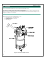
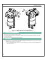
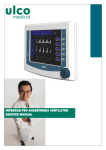
AB800 ABSORBER
USER MANUAL
AB800 User Manual
This page intentionally left blank
2
AB800 User Manual
Copyright © 1993, 2005 by Ulco Medical
All rights reserved.
No part of this publication may be reproduced in any form, in an electronic retrieval system or otherwise,
without the written permission of the Ulco Medical.
All Ulco products are subject to a program of continuous development and the manufacturer reserves the right
to make alterations in design and equipment without prior notice.
Document Number: AB8-UM-001
Version: 1.3
3
AB800 User Manual
This page intentionally left blank
4
AB800 User Manual
Table of Contents
1 Introduction ................................................................
................................................................................................
..................................................................
.................................. 7
1.1
Warranty Statement.......................................................................................................... 7
1.2
About this manual............................................................................................................. 7
1.3
Intended Use..................................................................................................................... 8
1.4
Device Classification......................................................................................................... 8
1.5
Background....................................................................................................................... 8
1.6
Safety Precautions............................................................................................................ 9
1.6.1
Before the first use............................................................................................... 9
1.6.2
Follow the Instructions for Use............................................................................. 9
1.6.3
Liability for proper function or damage ................................................................ 9
1.6.4
Maintenance and Repairs.................................................................................... 9
1.6.5
Use of anaesthetic agents ................................................................................... 9
1.6.6
Power Connection ................................................................................................ 9
1.6.7
Monitoring and alarms ....................................................................................... 10
2 Using the Absorber ................................................................
.....................................................................................
..................................................... 11
2.1
Background..................................................................................................................... 11
2.2
Mounting......................................................................................................................... 11
2.3
Circle Circuits .................................................................................................................. 12
2.4
Physical Features............................................................................................................ 12
2.5
2.6
2.4.1
Scavenge Connector .......................................................................................... 13
2.4.2
Ventilator hose connector .................................................................................. 13
2.4.3
Identification Label............................................................................................. 13
2.4.4
Manual Bag Arm................................................................................................. 13
AB800 Front and top view components ......................................................................... 14
2.5.1
The 22 mm. Inspiratory and Expiratory male cones:.......................................... 14
2.5.2
The Bypass Control............................................................................................. 14
2.5.3
Canister Assembly.............................................................................................. 15
2.5.4
Canister locking system ..................................................................................... 15
2.5.5
The Mode Control Knob ..................................................................................... 15
2.5.6
The APL Valve..................................................................................................... 16
2.5.7
The Fresh Gas Connector................................................................................... 16
2.5.8
The Patient Pressure manometer connector ..................................................... 16
Circuits............................................................................................................................ 17
5
AB800 User Manual
2.6.1
Circle system ...................................................................................................... 17
3 Care and Cleaning ................................................................
......................................................................................
...................................................... 19
3.1
Cleaning intervals ........................................................................................................... 19
3.2
Methods for cleaning the AB800 Absorber: ................................................................... 19
3.2.1
Method A ............................................................................................................ 19
3.2.2
Method B............................................................................................................ 19
4 Servicing and Maintenance ................................................................
........................................................................
........................................ 25
4.1
AB800-99 Service Kit ..................................................................................................... 25
4.2
Tools to be used ............................................................................................................. 25
4.3
Preparation to Service AB800 Absorber......................................................................... 26
4.4
Service Procedure........................................................................................................... 26
4.5
Test of AB800 absorber.................................................................................................. 34
5 Technical Information ................................................................
.................................................................................
................................................. 35
5.1
Principle of operation...................................................................................................... 35
5.2
Control of excess gases .................................................................................................. 35
5.2.1
Automatic ventilation ......................................................................................... 35
5.2.2
Manual ventilation ............................................................................................. 35
5.3
Technical Specifications ................................................................................................. 35
5.4
Test Standards................................................................................................................ 35
5.5
Symbols .......................................................................................................................... 36
6 Assembly Drawings................................
Drawings ................................................................
.....................................................................................
..................................................... 37
7 Terms and conditions ................................................................
.................................................................................
................................................. 44
6
AB800 User Manual
1 Introduction
Introduction
1.1
Warranty Statement
All Ulco products are guaranteed to be free of defects of workmanship or material for a period of two years
from the date of delivery. The following are exceptions to this warranty:
1. Defects caused by misuse, mishandling, tampering or by modifications not authorized by Ulco are not
covered.
2. Rubber and plastic components and materials are warranted free of defects at the time of delivery.
Any product which proves to be defective in workmanship or material will be replaced, credited or repaired
with Ulco holding the option. Ulco is not responsible for deterioration, wear or abuse. In any case, Ulco will not
be liable beyond the original selling price.
Goods are subject to the terms of applicable warranty. Defective products will be accepted for return at Ulco's
discretion, and only during the warranty period. Application of this warranty is subject to the following
conditions:
1. Ulco or its authorized agents must be promptly notified, in writing upon detection of the defective material
or equipment.
2. Defective material or equipment, must be returned, shipping prepaid, to Ulco or its authorized agent.
3. Examination by Ulco or its authorized agent must confirm that the defect is in fact covered by the terms of
this warranty.
4. Ulco or its agent must receive notification in writing, of defective material or equipment no later than two
(2) weeks following expiration of this warranty.
In order to assume complete protection under this warranty, the installation and commissioning report, and/or
periodic manufacturer's service record (if applicable) must be returned to Ulco within 2 weeks of receipt of the
equipment.
The above is the sole warranty provided by Ulco. No other warranty expressed or implied is intended.
Representatives or agents of Ulco are not authorized to modify or amend the terms and conditions of this
warranty.
1.2
About this manual
This manual provides information for the preparation, assembly and maintenance of the AB800 CO2 circle
absorber, together with suitable equipment from the Ulco range. Although this equipment has been carefully
designed for simplicity of assembly and use, it is recommended that the contents of this manual be studied
before attempting preparation or maintenance of the equipment. Explanatory diagrams are provided in order
to help the reader understand the concepts described.
This manual is a supporting document for the operation and maintenance of the Ulco AB800 CO2 circle
absorber. It should be read in conjunction with other relevant information such as the manual(s) for the
vaporizer and anaesthesia machine (if applicable).
7
AB800 User Manual
1.3
Intended Use
The AB800 CO2 Absorber is a circle rebreathing system for providing continuous gas inhalation anaesthesia for
human adults and children (above 5kg body weight).
The apparatus is intended for used solely in an operating or induction room.
The apparatus is intended to be used with hospital anaesthetic workstations and ventilators complying with
IEC 60601-2-13.
The apparatus is intended to be use under the continuous control of a person suitably trained and clinically
qualified in its use.
To comply with the Anaesthetic workstation station standard IEC 60601-2-13, the AB800 CO2 Absorber must
be used with adequate monitoring and alarms. The stated monitors and alarms can be found in Section 1.6.7
of this manual.
1.4
Device Classification
The AB800 CO2 Absorber is classified as follows:
• Type CF applied part
1.5
Background
The forms the gas supply end of a circle rebreathing circuit for the purposes of anaesthetic gas delivery. It
provides the one-way valves which form the expiratory and inspiratory limbs of the circuit. It allows a means of
introducing fresh gas to the circuit via the inspiratory limb and provides means for controlled flow through a
soda-lime absorber canister on the expiratory limb of the circuit for the removal of CO2.
The system can be used with high flow, low flow or minimal flow of fresh gas for patient ventilation.
In addition, positive pressure ventilation may be delivered by means of a manual bag or a bellows system
driven by an anaesthetic ventilator (the ventilator is not part of the AB800). A manual switch controlled by the
user determines which of these positive pressure sources is connected to the circle system. The switch is
normally at the “bag” position for manual ventilation of the patient, and is switched to the “ventilator” position
when automatic ventilation is required.
The AB800 CO2 Absorber forms part of a semi-closed patient breathing system which employs a circle
absorber for the elimination of CO2. The system can be used with high flow, low flow or minimal flow of fresh
gas for patient ventilation.
The circle absorber section of the AB800 consists of a canister for the soda-lime absorbent and a machined
block containing the interconnections between the absorber system and the external connectors. The sodalime canister can accommodate up to 1 kg of soda-lime and is made of reusable polysulphone. The canister
fits to the under side of the AB800 system with a lever locking system.
The AB800 also employs a graduated lever control valve which allows the proportion of expired gas flowing
through the absorber to be controlled, allowing the patient's end tidal CO2 to be adjusted by the anaesthetist.
CO2 circle absorbers such as the AB800 are engineered to very high standards of design and finish and all
units are able to accommodate the most comprehensive specifications required in modern anaesthesia.
8
AB800 User Manual
The AB800 has been designed to be used in conjunction with the Signet 615 Anaesthetic Workstation, which
provides a mounting bracket suitable for attachment of the absorber.
1.6
1.6.1
Safety Precautions
Before the first use
The unit must be connected to an anaesthesia machine and tested in accordance with the pre-use checklist
supplied with the machine. When using the AB8000 with conventional Boyle's type anaesthesia machines the
user must ensure that the correct ventilation mode (Manual or Automatic) is selected on the absorber prior to
commencing ventilation of the patient. Select VENTILATOR for mechanical ventilation or MANUAL BAG for hand
ventilation.
1.6.2
Follow the Instructions for Use
In order to use the equipment, these instructions must be fully read and understood and strictly followed. Any equipment
mentioned is only to be used for the intended purpose.
1.6.3
Liability for proper function or damage
This equipment is an adjunct to patient safety and it must in no way replace the normal monitoring by skilled personnel.
The manufacturers accept no responsibility for incidents arising from either incorrect use or malfunction of this
equipment.
If the equipment is serviced or repaired by persons not employed or authorised by Ulco, or if the equipment is not used
for the purposes for which it is intended, then the liability for the proper function of the equipment is transferred to the
owner/operator.
Where, the Signet 615 is assembled with other components of an anaesthetic system, such as ventilators or breathing
systems, and Ulco did not supply these components, then the personnel performing the assembly are responsible for
providing a checklist for the anaesthetic system.
1.6.4
Maintenance and Repairs
An authorised Ulco Technical Service Representative must perform maintenance of this equipment. Ulco products in
need of factory repairs must be sent to the nearest local agent or direct to Ulco.
Ulco recommends that anaesthesia products/equipment be serviced at intervals stated in Section Error! Reference
source not found. of this manual. Periodic Manufacturer’s Service Contracts are available for products manufactured and
or sold by Ulco. These agreements are available from Ulco Technical Services.
1.6.5
Use of anaesthetic agents
Explosive anaesthetic agents, such as ether or cyclopropane, must not be used due to the risk of fire. Ulco accepts no
liability if the wrong anaesthetic agent is used.
1.6.6
Power Connection
Ulco equipment is to be used only in rooms with mains power supply installations complying with national safety
standards.
Electrical connections for other equipment not listed here should only be made following consultations with the
respective manufacturers or other expert.
For full details of the electrical environment in which the Signet may be used see Section Error! Reference source not
found. of this document.
9
AB800 User Manual
1.6.7
Monitoring and alarms
If the unit alarms, check the patient. Establish that the patient is being ventilated correctly.
This unit must be used in conjunction with equipment providing the following alarms and monitoring capabilities:
• Inspiratory oxygen concentration
• Anaesthetic agent concentration
• Airway pressure
• CO2 concentration
• Exhaled volume
• Breathing system integrity
• Continuing pressure
These will help ensure patient safety, make precise ventilation possible and so achieve the best possible ventilator
parameters for the patient.
10
AB800 User Manual
2 Using the Absorber
Absorber
2.1
Background
CO2 circle absorbers such as the AB800 are engineered to very high standards of design and finish and all
units are able to accommodate the most comprehensive specifications required in modern anaesthesia. Circle
absorbers such as the AB800 are designed to be used with anaesthetic machines such as the Signet 615
which provides a mounting bracket suitable for attachment of the absorber. The Signet 615 can also be
upgraded from its basic configuration with other optional accessories and attachments including a full range
of patient monitors to provide a comprehensive anaesthesia workstation.
2.2
Mounting
The soda-lime absorber mount bracket attaches to the post towards the front of the machine. The absorber
mount sits over the upright and should be allowed to seat itself into position. The top locking screw and side
locking screw can then be fastened to hold in position. The exhaust (Pink scavenge hose) can then be
attached to the 30mm exhaust valve scavenging outlet. The absorber fresh gas hose from the common gas
outlet can now be connected to the fresh gas inlet on the side of the absorber. This connection hose is made
from strong Polyurethane hose so it will not perish. No latex tubing is used in Ulco machines.
Figure 1: Mounting the AB800 absorber
11
AB800 User Manual
2.3
Circle Circuits
ircuits
For this the absorber fresh gas input is connected to the common gas outlet.
Ulco absorber 1 or 2kg model with bag/vent switch (Part No AB 800)
This version has separate limbs for the ventilator and manual bag. Selection is made by switching the knob,
either to the bag or ventilator position. This version eliminates the need to remove the manual bag from the
single limb to attach it to the ventilator.
2.4
Physical Features
When viewed from the back the following can be seen:
• Scavenge connector 30mm Male cone
• Ventilator bellows hose connector
• Identification Label
• Manual Bag Arm
•
Figure 2: Rear view of AB800 absorber
12
AB800 User Manual
2.4.1
Scavenge Connector
The Pink scavenge hose connector is fitted with 2 different size connectors:
1 x 19 mm. Male connector
1 x 30 mm Female connector
The 19 mm male connector attaches to the Scavenge block of the anaesthetic machine and the 30 mm
female connector is connected to the absorber 30 mm male cone.
2.4.2
Ventilator hose connector
The blue Ventilator Hose is connected to the 22 mm male cone at the back of the absorber and the other end
is connected to the ventilator patient 22 mm male cone.
2.4.3
Identification Label
The Identification label has the name and address of the manufacturer as well as the serial number engraved.
The serial number must be stated when information regarding the unit is sought.
2.4.4
Manual Bag Arm
The manual re-breathing bag fitted with a male bag mount, is connected to the 22 mm. Female port on the
swivel arm.
When viewed from the front and top the following can be seen:
• 22/15mm Inspiratory Male cone
• ON / OFF Control
• 22/15mm Expiratory Male cone
• Canister assembly
• Canister support
• Canister locking system
• Ventilation Mode Control Knob
• APL Valve (This valve also acts as a Pressure limiting valve and is factory set to max 80 cm/H2O but
can be set lower)
• Removable valve cover
• Silicone shutter unidirectional valves
• Fresh Gas Connector
• Patient Pressure manometer connector
13
AB800 User Manual
Figure 3: Front and side view of AB800 absorber
2.5
2.5.1
AB800 Front and top view components
The 22 mm. Inspiratory and Expiratory male cones:
The white (clear) circuit hoses from the patient ‘Y’ piece are connected to these 2 cones.
2.5.2
The Bypass Control
This control is used to bypass the soda lime absorber so that the patient re-breaths some of the exhaled gases
in order to raise the CO2 level. This control may be used in place of a reduced ventilation rate to elevate the
CO2 level, because when reducing the ventilator rate, the O2 level is also reduced; whereas using the bypass
control on the absorber, only the CO2 level is increased.
The amount of re-breathing may be increased, by turning the control to the left, or decreased by turning the
control to the right.
14
AB800 User Manual
Note
The Bypass control in the absorber OFF position is also used to isolate the canister(s) and enable soda lime
recharge during a procedure. No fresh gas loss will occur if the canister(s) are removed during use when
Bypass control is in the absorber OFF position. Ensure that canisters are filled with fresh soda lime at the start
of procedure(s).
2.5.3
Canister Assembly
The AB800 can be supplied with a single plus spare canister (1 kg.), or with dual canisters as a 2 kg assembly.
The canisters are made from polysulphone and can be autoclaved.
2.5.4
Canister locking system
To remove the canister(s), undo the handle latch by turning sideways, then push the canister(s) release handle
down to vertical until canister(s) are free. Push canister(s) down then out of the cradle. To insert canister(s),
place the raised part of the base plate into the recess of the sliding plate, and lift the canister release handle
up and latch.
2.5.5
The Mode Control Knob
This knob must be used to select either manual or mechanical ventilation. In Ventilator Mode, the expired
gases are channelled direct from the expiratory port and shutter valve, to the ventilator bellows. When the
bellows are compressed to deliver a breath, the gases are returned to the patient via the Soda Lime and fresh
gas input, to the Inspiratory port via the Inspiratory shutter valve.
If the bypass control is fully to the right, the absorber is ON. (See page 9 for more information). All of the
delivered gas volume is passed through the soda lime before it is delivered to the patient. If the bypass control
is set towards the left, the absorber is OFF, and depending on the setting, some or all of the delivered volume
will bypass the soda lime before it is delivered to the patient. This is used to adjust the inspired CO2 level.
Excess gas spill is automatically controlled by the ventilator.
Set the control to the OFF position before removing the canister to replace soda lime.
In the Manual Bag Mode, the expired gases are channelled direct from the expiratory port and shutter valve, to
the re-breathing bag and to the APL valve. When the bag is compressed to deliver a breath, the gases are
returned to the patient via the Soda lime and fresh gas input, to the Inspiratory port via the Inspiratory shutter
valve. If the bypass control is fully to the right all the delivered volume is passed through the soda lime before
it is delivered to the patient. If the bypass control is set towards the left, depending on the setting, some or all
of the delivered volume will bypass the soda lime before it is delivered to the patient; this is used to adjust the
inspired CO2 level.
15
AB800 User Manual
2.5.6
The APL Valve
This valve controls the spill (excess gas flow) in the circuit and has to be manually adjusted to the required
setting by the operator. The excess gas spilled by the APL valve is channelled direct to the scavenging system
via the 30 mm male connector at the rear of the absorber head. The APL valve will only rotate through 360O
and has a range from 0 to 80 cm/H2O. The maximum pressure limit setting is adjustable. Factory setting is 80
cm/H2O. The APL valve maximum setting can be set between 80 or 60 cm/H2O by removing the control knob
and moving the cir-clip to the lower slot. Connect the ‘Y’ piece to the manual BAG port with a manometer
gauge in between when adjusting the APL valve as a bag limits the pressure to about 40 cm/H2O.
Open fully when spontaneous ventilation is selected. Minimum pressure is 2 – 3 cm/H2O
Figure 4: Location and sectional view of APL valve
2.5.7
The Fresh
Fresh Gas Connector
This connector is used to attach the Fresh Gas Hose from the Patient Block CGO on the anaesthetic machine
to the AB800 Absorber.
2.5.8
The Patient Pressure manometer connector
This connector accepts a quick connect system, either direct or via a small bore tube to a manometer or other
patient pressure measuring device and is used for connecting to a workstation. A rear mounted manometer
can be fitted for use with standard machines.
16
AB800 User Manual
2.6
2.6.1
Circuits
Circle system
Patient usage:
Ensure that the proposed breathing circuit is compatible with the AB800 Absorber.
Turn on the ventilator and adjust the timing, volume and pressure to approximate requirements. Connect the
patient and then make the final fine adjustments to suit the characteristics of the lungs (i.e. individual
variation in compliance, airways resistance and required minute volume). Check that the expiratory pressure
falls to zero (unless PEEP is set) at each cycle (i.e. no obstruction in the expiratory pathway).
Pollution control systems may be attached to the exhaust of the ventilator. It is important to guard against
possible obstruction and excess suction. Both will be indicated on the ventilator gauge (not returning to zero if
obstructed or the bellows being sucked up during the expiratory period if the suction is too high and a negative
pressure is being generated).
Confirm adequate ventilation of the patient by observing good chest movement with each inspiration. Make
sure all connections are leak free and firmly connected. Unnecessary high inspiration pressures should be
avoided. Set the inspiratory pressure and time so that the selected volume is delivered just before the
inspiration ends to obtain a plateau. With the circle system ensure that the absorber is turned to VENTILATOR
mode if mechanical ventilation is selected or to MANUAL BAG if manual or spontaneous ventilation is selected.
17
AB800 User Manual
This page intentionally left blank
18
AB800 User Manual
3
3.1
Care and Cleaning
Cleaning intervals
The absorber should be cleaned on a regular basis and in accordance with Hospital Infection Control
guidelines, usually after an infected case, or at the end of each day.
If an inline bacterial filter is fitted to the expiratory port of the absorber, cleaning will only be needed once a
month.
Note:
Note: The filter should be replaced in accordance with the manufacturer’s recommendations.
3.2
3.2.1
Methods
Methods for cleaning the AB800 Absorber:
Method A
Wash with mild soap and warm water, or if contaminated the whole absorber may be gas sterilised. A
disinfectant may be diluted with the water. First wipe the whole absorber with a damp sponge containing
disinfectant, then remove the lid and shutter valves and wipe down.
3.2.2
Method B
Dismantle the absorber as follows.
1. Loosen the knurled screws and remove the clear lid
Figure 5: Removing the absorber lid screws
19
AB800 User Manual
Figure 6: Removing the absorber lid
2. Remove the silicone shutters by gently lifting from the base NOT from the flaps.
Figure 7: Removing the silicon shutter valves
20
AB800 User Manual
3. To release and remove the canister(s), undo the handle latch by turning sideways.
Figure 8: Unlocking the canister release mechanism
4. Push the release handle down to vertical until canisters are free.
21
AB800 User Manual
Figure 9: Operating the canister release mechanism
5. Push canister(s) down then out of the cradle. Then dispose used soda lime (see suppliers recommended
procedure for disposal of soda lime).
22
AB800 User Manual
Figure 10: Removing the soda lime canisters
6.
7.
8.
9.
Wash all the absorber components. Do NOT use caustic cleaning fluids.
The Canister(s) and silicone shutter can be autoclaved.
The Absorber head can be put through a washer at 80O
Dry thoroughly before assembly, low pressure warm air should be passed trough the head by attaching a
hose to the expiratory port of the absorber.
23
AB800 User Manual
This page intentionally left blank
24
AB800 User Manual
4 Servicing and Maintenance
4.1
AB800AB800-99 Service Kit
-
4.2
1 off OR-5008
2 off OR-5014
1 off OR-5017
1 off OR-5021
1 off OR-5024S
3 off OR-5028
1 off OR-5042
1 off OR-5113S
1 off OR-5114
1 off OR-5115S
1 off OR-5116
5 off OR-5117
1 off OR-5218S
2 off OR-5224S
2 off OR-5356S
1 off OR-5432
2 off AB802262
2 off WAM6P
2 off WA-DZUS
O-ring
O-ring
O-ring
O-ring
O-ring
O-ring
O-ring
O-ring
O-ring
O-ring
O-ring
O-ring
O-ring
O-ring
O-ring
O-ring
U-Cap
Washer
Washer
Tools to be used
-
1.5mm, 2.5 mm and 4 mm Allen keys
Philips screwdriver
Flat screwdriver
1” spanner
Silicone grease Molykote 111.
25
AB800 User Manual
Figure 11: AB800 Absorber Front and Rear View
4.3
4.4
Preparation to Service AB800 Absorber
Make sure that the anaesthetic machine is OFF.
Disconnect AB800 absorber from anaesthetic machine. This is remove inspiration, expiration, scavenger
and fresh gas hoses.
Disconnect quick fitting to monitor patient pressure.
Service Procedure
1. Replacement of o-rings OR-5116, OR-5218S, OR-5432S and OR-5356S by removing the two canisters
AB20401. Refer to Figure 12 and Figure 13.
a. Turn the AB203040 handle retainer (the one that hold into lock position the handle AB203041) to
the release position.
26
AB800 User Manual
Figure 12: Unlocking Canisters
b. Push down the handle AB203041 and then remove the subassembly canister AB20401, base
plate AB20402 and tube assembly AB205 from the AB800 absorber.
c. Replace o-rings OR-5116, OR5218S, OR-5432S and OR-5356S then smear them with silicone
grease Molykote 111.
d. Reassemble o-rings and the other components in the reversal order as they were disassembled.
e. With the canister AB20401 in its working position pull up the handle AB203041 and lock it in
position by turning the handle retainer AB203040.
27
AB800 User Manual
Figure 13: Removal of o-rings on canister assembly
2. Replacement of o-rings OR-5117 from the CO2 control spool AB802054.. See Figure 14..
a. Unscrew the lever ON-OFF of the CO2 control spool valve AB802052.
b. Remove the knob AB802051 and then remove the three screws SM0316C with a Philips
screwdriver.
c. Reassemble the lever ON-OFF AB802052 and pull out the spool subassembly valve AB802054
and spool retainer AB802053.
d. Replace and smear with silicone grease the three o-rings OR-5117.
e. Reassemble the components in the reverse way they were disassembled.
28
AB800 User Manual
Figure 14: Removal of O-ring OR-5117 from spool assembly
3. Service of o-rings OR-5117 and OR-5115 from AB8023 Manual Bag Assembly. Refer to Figure 15.
a. Remove the two screws SM0616CSK from the AB8023 manual bag assembly with a 4mm Allen
key.
b. Pull out the AB8023 manual bag assembly from the AB8021 absorber head.
c. Replace and smear with silicone grease Molykote 111 the o-ring OR-5115.
d. By using a 1” spanner unscrew the AB802306 bolt from the AB802304 adaptor tube.
e. Replace and smear with silicone grease the two o-ring OR-5117.
f. Reassemble o-rings and the other components in the reversal order as they were disassembled.
29
AB800 User Manual
Figure 15: Service of o-rings from Manual Bag Assembly AB8023
4. Service of o-rings OR-5024S, OR-5021 and OR-5113S from the APL valve EX800. Refer to Figure 16.
a. Unscrew SM0506G grub screw from the APL valve control knob EX801 by using a 2.5mm Allen
key.
b. Remove the APL control knob EX801 from the APL valve EX800.
c. Remove the SM0305G grub screw with a 1.5mm Allen key and then unscrew and remove the
EX802 body from the AB800 absorber.
d. Replace the o-ring OR-5024S and smear it with silicone grease Molykote 111.
e. Remove the actuator adjustor EX804 with a flat screwdriver from the removed EX800 APL valve.
f. Replace the o-ring OR-5113S and smear it with silicone grease Molykote 111.
g. To replace the o-ring OR-5021 removes the circlip EX8031 from any of the ends of the EX803
actuator housing.
h. Reassemble o-rings and the other components in the reversal order as they were disassembled.
30
AB800 User Manual
Figure 16: Service of o-ring on APL Valve Assembly EX800
5. Service of o-rings OR-5224S and replacement of washers WAM6P and WA-DZUS from absorber head
AB8021. Refer to Figure 17.
a. To replace the o-rings OR-5224S unscrew by hand the fasteners AB80102.
31
AB800 User Manual
b. Pull out the lid AB80101 and then replace the two o-rings OR-5224S and smear them with silicone
grease.
c. Replace the washers WA-M6P and WA-DZUS.
d. Reassemble the lid AB80101 and screw the fasteners AB80102 back in to the AB800 absorber.
Figure 17: Service of o-rings under lid AB80101
6. Service of the o-rings OR-5028 and OR-5042 from the absorber head AB8021. Refer to Figure 18.
a. Remove plugs HPLG08 and then unscrew the four SM0550SC screws with a 4mm Allen key.
b. Pull out absorber valve housing AB801 and replace o-rings OR-5028 and OR-5042, but smear
them with silicone grease when assemble.
c. Reassemble the other components in the reversal order as they were disassembled.
32
AB800 User Manual
Figure 18: Service of o-rings under AB801 Valve Housing Absorber
7. Service of the U-cap AB802262 and o-ring OR-5008 from under AB801 Absorber Head. See Figure 19.
a. Remove grub screws SM0506G from Bag/Vent Switch AB80221
b. Remove Bag/Vent Switch AB80221
c. Turn around the absorber head and remove the screws SM0420CSK with a Phillips screw driver.
d. Remove the shaft AB80223 and other components.
e. Remove the U-caps AB802262 with a flat screwdriver and replace them with new ones, smear
them with Molykote grease.
f. Replace o-ring OR-5008 from shaft AB80223 and also smear it with Molykote grease.
g. Reassemble all components in the reverse way they were removed, including the reassembly of
AB801 Valve Housing into AB800 Absorber.
33
AB800 User Manual
Figure 19: Service of Bag Vent Switch
4.5
Test of AB800 absorber
absorber
1. Preparation:
a.
b.
c.
d.
e.
Remove EX801 knob
Connect quick fitting to monitor patient pressure.
Connect medical gas supply to the machine.
Connect fresh gas hose to AB800 absorber.
Switch ON the anaesthetic machine.
2. Calibration of AB800 absorber.
a.
b.
c.
d.
e.
f.
g.
34
Open Oxygen knob fully on the fresh gas rotameter
Close the APL valve
Move the cir-clip to the lower slot.
Connect the ‘Y’ piece to the manual BAG port with a manometer gauge in between when
adjusting the APL valve as a bag limits the pressure to about 40 cm/H2O.
Using a large flat bladed screwdriver, adjust the EX804 body so that the maximum pressure is
between 70 and 80 cmH2O
Open the valve fully. Adjust the EX804 body so that the minimum pressure is 2 – 3 cmH2O
Replace the circlip and the EX801 knob
AB800 User Manual
5 Technical Information
5.1
Principle of operation
Fresh gas from the common gas outlet passes via the fresh gas hose connector into the absorber upstream of
the Inspiratory silicone shutter valve, the position of the fresh gas entry is such that the shutter valve prevents
fresh gas from entering the inspiratory limb during expiration. Fresh gas enters the Inspiratory limb during
inspiration to the patient, and passes to the expiratory limb during expiration.
From the expiratory port gas passes via the expiratory shutter valve into the selection chamber in the absorber
head. This chamber has a single input port and two output ports: one output port is connected to the
VENTILATOR channel and the other output port is connected to the MANUAL BAG channel.
The Mode control when turned to either VENTILATOR or MANUAL BAG selects that particular channel and
closes off the other, thus allowing the expired gas to flow either to the ventilator bellows or the manual bag
depending on the mode selected.
Squeezing the bag or bellows, forces the gas through the soda lime canister. As the expiratory shutter valve
prevents flow back to the expiratory limb, the only port open is the one leading to the soda lime chamber and
back to the inspiratory port, the flow from this port can be diverted by the bypass valve so that all or part of the
volume passes through the soda lime thus allowing a controlled amount of exhaled gas containing expired
CO2 to be channelled into the inspiratory line where it joins the fresh gas to be delivered to the patient.
5.2
Control of excess gases
5.2.1
Automatic ventilation
During controlled (mechanical) ventilation the ventilator controls the spill of excess gas and channels that
excess to the scavenge system.
5.2.2
Manual ventilation
When on Manual or Spontaneous ventilation, the APL valve is adjusted to set the spill of excess gas and divert
that spill to the scavenge system if fully open a PEEP of 2 to 3 cm/H2O is normal.
5.3
Technical Specifications
Resistance@ 60 LPM:
Absorber compliance:
Leakage:
Exp. 6 cmH2O, Insp. 5 cmH2O
0.9 ml/hPa
50 ml/min
Soda lime capacity of reusable absorber canister:
1000g (enough to absorb about 130 L of CO2)
One-way shutter valve, pressure generated (when wet): 1.2 cm/H2O
One-way valve, opening pressure (when wet):
1.0 cm/H2O
Weight:
5.4
5 kg (without absorbent)
Test Standards
The ventilator was tested in accordance with the following standards to ensure that any faults do not result in
dangerous conditions:
Functional safety:
IEC 60601-2-13, ISO 8835-2
35
AB800 User Manual
5.5
Symbols
These symbols may appear on the workstation and its associated equipment.
Symbols
Refer to
accompanying
documents
36
Protective
Earth
Equipotential
Grounding
Alternating
Current
Manufacturer
Power Off
(pneumatic
and electrical)
Type CF
Applied Part
Date of
Manufacture
Power On
(pneumatic
and electrical)
AB800 User Manual
6 Assembly Drawings
•
Exploded view of Absorber Head and Canisters.
•
Assembly drawings.
37
AB800 User Manual
ULCO MEDICAL
APL VALVE
ULCO
MEDICAL
38
AB800 ABSORBER
AB800 User Manual
AB800 ABSORBER
39
AB800 User Manual
APL VALVE
ULCO
MEDICAL
40
AB800 User Manual
41
AB800 User Manual
42
AB800 User Manual
43
AB800 User Manual
7
Terms and conditions
All merchandise to be returned must have prior written authorisation by Ulco, and a valid Return Goods
Authorisation (RGA) number shall appear on the shipping label, packing slip, purchase order and any
other related documents. When requesting authorisation to return material, the following information
should be provided:
1.
2.
3.
4.
Customer purchase order and date.
Ulco invoice number and date, and method of shipment (See delivery document).
Part number, quantity, and description of goods to be returned.
Reason for returning goods.
The following are acceptable reasons for return of goods:
1. Material failure within warranty period.
2. Service or repairs.
3. Ordered in error or duplication of order.
Any shipping errors or shortages of goods must be reported to Ulco within seven (7) days of receipt of such
goods.
Goods are subject to any terms of any applicable warranty. Premature failure of products shall be accepted
for return at Ulco’s discretion, and only during the warranty period.
Goods to be returned which are not under warranty should have been purchased within thirty days of request
for return, and returned within thirty days after request. Goods shall be returned unused, and in Ulco
containers. Goods may be subject to a 20% restocking charge, with the exception of goods failure within the
warranty period or due to Ulco error.
The following merchandise is not eligible for return, unless proven defective:
1.
2.
3.
4.
Sterile material, unless shipped in error by Ulco.
Rubber and plastic components that have been used.
Specially ordered or produced items.
Goods that have been altered or abused.
All items to be returned shall be shipped, including RGA number, to:
Ulco Medical
25 Sloane St
Marrickville NSW 2204
Australia
44
GOODS RETURN AUTHORISATION
RGA Number
Customer Details
Name
Address
State/Country
Postcode
Returned Product
Date of Purchase
Date of return
Reason for returning goods (please give a short description of the fault):
Signature
Return to
ULCO Medical
25 Sloane St
Marrickville NSW 2204
Australia
In the European Community, returned goods authorities should be obtained from:
Advena Ltd.
PO Box 30, Leominster HR6 0ZQ UK
Telephone +44(0)1568-620080
Fax +44(0)1568-620078