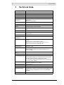
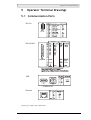
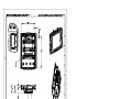
1
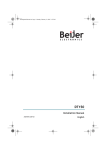
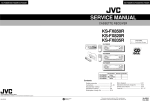
MITSUBISHI ELECTRIC Mac E Series Human Machine Interface Installation Manual E1101 Art. no.: 169279 10 02 2006 Version A MITSUBISHI ELECTRIC INDUSTRIAL AUTOMATION Foreword Installation manual for the E1000 series operator terminals Foreword The E1000 operator terminal is developed to satisfy the demands of humanmachine communication. Built-in functions such as displaying and controlling text, dynamic indication, time channels, alarm and recipe handling are included. The operator terminal work, for the most part, in an object-oriented way, making it easy to understand and use. The configuration operation of the terminal is made in a personal computer, using the configuration tool EDesigner. The project is then transferred and stored in the operator terminal. The operator terminal can be connected to many types of automation equipment, such as PLCs, servos or drives. In this manual the expression “the controller“ is used as a general term for the connected equipment. This manual explains how to install the operator terminal. Please refer to the reference manual for further information. Mitsubishi Electric AB, MA00779, 2005-01 The information in this document is subject to change without notice and is provided as available at the time of printing. The manufacturer reserves the right to change any information without updating this publication. The manufacturer assumes no responsibility for any errors that may appear in this document. Read the entire installation manual prior to installing and using this equipment. Only qualified personnel may install, operate or repair this equipment. The manufacturer is not responsible for modified, altered or renovated equipment. Because the equipment has a wide range of applications, users must acquire the appropriate knowledge to use the equipment properly in their specific applications. Persons responsible for the application and the equipment must themselves ensure that each application is in compliance with all relevant requirements, standards and legislation in respect to configuration and safety. Only parts and accessories manufactured according to specifications set by The manufacturer may be used. THE MANUFACTURER SHALL NOT BE LIABLE TO ANYONE FOR ANY DIRECT, INDIRECT, SPECIAL, INCIDENTAL OR CONSEQUENTIAL DAMAGES RESULTING FROM THE INSTALLATION, USE OR REPAIR OF THIS EQUIPMENT, WHETHER ARISING IN TORT, CONTRACT, OR OTHERWISE. BUYER’S SOLE REMEDY SHALL BE THE REPAIR, REPLACEMENT, OR REFUND OF PURCHASE PRICE, AND THE CHOICE OF THE APPLICABLE REMEDY SHALL BE AT THE SOLE DISCRETION OF THE MANUFACTURER. Mitsubishi Electric, MA00779 Foreword Mitsubishi Electric, MA00779 Table of Contents Table of Contents 1 Safety Precautions............................................................................. 1-1 1.1 UL Installation............................................................................... 1-1 1.2 General .......................................................................................... 1-1 1.3 During Use .................................................................................... 1-1 1.4 Service and Maintenance................................................................ 1-2 1.5 Dismantling and Scrapping............................................................ 1-2 2 Installation ....................................................................................... 2-1 2.1 Space Requirements ....................................................................... 2-1 2.2 Installation Process......................................................................... 2-1 2.2.1 Mode Switches ............................................................................................... 2-3 2.2.2 Connections to the Controller ........................................................................ 2-3 2.2.3 Other Connections and Peripherals ................................................................ 2-3 3 Technical Data ................................................................................. 3-1 4 Chemical Resistance ......................................................................... 4-1 4.1 Metal Casing.................................................................................. 4-1 4.2 Keyboard and Display.................................................................... 4-1 4.2.1 Autotex F250.................................................................................................. 4-1 4.2.2 Touch Screen Surface ..................................................................................... 4-2 5 Operator Terminal Drawings ........................................................... 5-1 5.1 Communication Ports.................................................................... 5-1 5.2 E1101 Outline ............................................................................... 5-2 Mitsubishi Electric, MA00779 Table of Contents Mitsubishi Electric, MA00779 Safety Precautions 1 Safety Precautions Both the installer and the owner and/or operator of the operator terminal must read and understand this installation manual. 1.1 UL Installation Power, input and output (I/O) wiring must be in accordance with Class 1, Division 2 wiring methods (Article 501-4 (b) of the National Electric Code, NFPA 70) and in accordance with the authority having jurisdiction. 1.2 General – Only qualified personnel may install or operate the operator terminal. – The operator terminal must be installed according to the installation instructions. – The operator terminal is designed for stationary installation on a plane surface, where the following conditions are fulfilled: • no high explosive risks • no strong magnetic fields • no direct sunlight • no large, sudden temperature changes – Never allow fluids, metal filings or wiring debris to enter any openings in the operator terminal. This may cause fire or electrical shock. – The operator terminal fulfills the requirements of article 4 of EMC directive 89/336/EEC. – Storing the operator terminal where the temperature is lower/higher than recommended in this manual can cause the LCD display liquid to congeal/become isotopic. – The LCD display liquid contains a powerful irritant. In case of skin contact, wash immediately with plenty of water. In case of eye contact, hold the eye open, flush with plenty of water and get medical attention. – The supplier is not responsible for modified, altered or reconstructed equipment. – Use only parts and accessories manufactured according to specifications of the supplier. – Peripheral equipment must be appropriate for the application and location. – The figures in this manual serves an illustrative purpose. Because of the many variables associated with any particular installation, the supplier cannot assume responsibility for actual use based on the figures. – The supplier neither guarantees that the operator terminal is suitable for your particular application, nor assumes responsibility for your product design, installation or operation. 1.3 During Use – Keep the operator terminal clean. – Emergency stop and other safety functions may not be controlled from the operator terminal. – Do not use too much force or sharp objects when touching the keys, display etc. Mitsubishi Electric, MA00779 1-1 Safety Precautions 1.4 Service and Maintenance – Only qualified personnel should carry out repairs. – The agreed warranty applies. – Before carrying out any cleaning or maintenance operations, disconnect the equipment from the electrical supply. – Clean the display and surrounding front cover with a soft cloth and mild detergent. – Replacing the battery incorrectly may result in explosion. Only use batteries recommended by the supplier. 1.5 Dismantling and Scrapping – The operator terminal or parts thereof shall be recycled according to local regulations. – The following components contain substances that might be hazardous to health and the environment: lithium battery, electrolytic capacitor and display. 1-2 Mitsubishi Electric, MA00779 Installation 2 Installation 2.1 Space Requirements – Installation plate thickness: 1.5 - 9.0 mm (0.06 - 0.35 inch) – Space requirements when installing the operator terminal: 100 mm (4.0 inch) 228 mm (8.98 inch) 50 mm (2.0 inch) 100 mm (4.0 inch) 50 mm (2.0 inch) 100 mm (4.0 inch) 302 mm (11.89 inch) 58 mm (2.28 inch) Caution The openings on the enclosure are for air convection. Do not cover these openings. 2.2 Installation Process 1. Unpack and check the delivery. If damage is found, notify the supplier. Panel cut out 264.5 x 206.0 mm (10.41 x 8.11 inch) x 13 Note: Place the operator terminal on a stable surface during installation. Dropping it or letting it fall may cause damage. 2. Place the panel cut out where the operator terminal is to be situated, draw along the outer sides of the holes and cut according to the markings. Mitsubishi Electric, MA00779 2-1 Installation 3. Secure the operator terminal in position, using all the fastening holes and the provided brackets and screws: x 13 0.5 - 1.0 Nm 4. Connect the cables in the specified order. A B C D Caution Ensure that the operator terminal and the controller system have the same electrical grounding (reference voltage level), otherwise errors in communication may occur. Use an M5 screw and a grounding conductor (as short as possible) with a cross-section of minimum 2.5 mm2. Caution - Use only shielded communication cables. - Separate high voltage cables from signal and supply cables. Caution - The operator terminal must be brought to ambient temperature before it is started up. If condensation forms, ensure that the operator terminal is dry before connecting it to the power outlet. - Ensure that the voltage and polarity of the power source is correct. Power Controller CF CARD B 1 RS422/RS485 24V DC RS232 C 24V DC D A Ethernet 5. Carefully remove the laminated film over the operator terminal display, to avoid static electricity that could damage the terminal. 2-2 Mitsubishi Electric, MA00779 Installation 2.2.1 Mode Switches All mode switches must be in OFF position during operator terminal use. The mode switches should not be touched unless by qualified personell. ON DIP 1 2 3 4 MODE EXPANSION ON DIP 1 2 3 4 MODE CF CARD BUSY 1 24V DC COM 2 RS232 10/100 COM 1 RS422 RS485 2.2.2 Connections to the Controller For information about the cables to be used when connecting the operator terminal to the controller, please refer to the help file for the driver in question. 2.2.3 Other Connections and Peripherals Cables, peripheral equipment and accessories must be suitable for the application and its environment. For further details or recommendations, please refer to the supplier. Caution When using a compact flash card, do not remove the card when the busy indicator is illuminated. Mitsubishi Electric, MA00779 2-3 Installation 2-4 Mitsubishi Electric, MA00779 Technical Data 3 Technical Data Parameter E1101 Front panel, W x H x D 302 x 228 x 6 mm Mounting depth 58 mm (158 mm including clearance) Front panel seal IP 66 Rear panel seal IP 20 Keyboard material/ Front panel Touch screen: Polyester on glass *, 1 million finger touch operations. Overlay: Autotex F250 *. Reverse side material Powder-coated aluminum Weight 2.0 kg Serial port RS422/ RS485 25-pin D-sub contact, chassis-mounted female with standard locking screws 4-40 UNC. Serial port RS232C 9-pin D-sub contact, male with standard locking screws 4-40 UNC. Ethernet Shielded RJ 45 USB Host type A, power consumption max. 500mA Device type B CF-slot Compact flash, type I and II Flash memory for application 4 MB Real time clock ±20 PPM + error because of ambient temperature and supply voltage. Total max error: 1 min/month at 25 °C Minimum life of the real time clock battery: 3 years Temperature coefficient: 0.004 ppm/°C2 Power consumption at rated voltage Normal: 0.5 A Maximum: 1.0 A Display TFT-LCD. 800 x 600 pixels, 64K color. CCFL backlight lifetime at the ambient temperature of +25 °C: 50,000 h. Active area of display, WxH 211.2 x 158.4 mm Fuse Internal DC fuse, 3.15 AT, 5 x 20 mm Power supply +24V DC (20 - 30V DC). 3-pin jack connection block. CE: The power supply must conform with the requirements for SELV or PELV according to IEC 950 or IEC 742. UL: The power supply must conform with the requirements for class II power supplies. Ambient temperature Vertical installation: 0 ° to +50 °C Horizontal installation: 0 ° to +40 °C Storage temperature -20 ° to +70 °C Relative humidity 5 - 85 % non-condensed EMC tests on the operator terminal The operator terminal conforms with the essential protection requirements in article 4 of the directive 89/336/EEC. Noise tested according to EN6100-6-4 emission and EN61000-6-2 immunity. UL, cUL approvals Certification in progress * See section Chemical Resistance for keyboard and display Mitsubishi Electric, MA00779 3-1 Technical Data 3-2 Mitsubishi Electric, MA00779 Chemical Resistance 4 Chemical Resistance 4.1 Metal Casing The frame and casing material is powder-coated aluminum. This powder paint withstands exposure of up to 24 hours duration to the following chemicals without visible change: Ammonia 25% Isopropyl alcohol Nitric acid 3% De-ionized water Tap water Chlorhydric acid 10% Butanol Cooling liquid 50% Washer fluid 33% Citric acid 10% Ligroin Sulphuric acid 20% Diesel Cooking oil Turpentine Ethanol 99.5% denaturated Lactic acid 10% Urea saturated FAM-Normal petrol Sodium di-chromate saturated Hydroperoxide 3% Alcohol 95% Caustic soda 5% Acetic acid 10% Phosphoric acid 43% Sodium hypochlorite solution Alu-cleaner Glycol Sodium carbonate 10% - Industrial petrol Sodium chloride 20% - 4.2 Keyboard and Display 4.2.1 Autotex F250 Autotex F250 covers the overlay surrounding the touch screen. Solvent Resistance Autotex F250 withstands exposure of more than 24 hours duration under DIN 42 115 Part 2 to the following chemicals without visible change: Potassium ferrocyanide/ ferricyanide Sodium hypchlorite <20% (bleach) 1.1.1. Trichloroethane (Genklene) Cyclohexanol Acetaldehyde Ethylacetate Diacetone alcohol Aliphatic hydrocarbons Diethyl ether Glycol Toluene N-Butyl acetate Isopropanol Xylene Amylacetate Glycerine White spirit Butycellosolve Methanol Fromic acid <50% Ether Triacetin Acetic acid <50% MIBK Dowanol DRM/PM Phosphoric acid <30% Cutting oil Acetone Hydrochloric acid <36% Potassium carbonate Metyl ethyl ketone Nitric acid <10% Washing powders Dioxan Trichloracetic acid <50% Fabric conditioner Cyclohexanone Sulphuric acid <10% Ferric chloride Ethanol Formaldehyde 37% - 42% Ferrous chlorid Isophorone Potassium hydroxide <30% Dibutyl Phthalate Mitsubishi Electric, MA00779 4-1 Chemical Resistance Ammonia <40% Linseed oil Dioctyl Phthalate Caustic soda <40% Paraffin oil Sodium carbonate Hydrogen peroxide <25% Blown castor oil Petrol Alkalicarbonate Silicone oil Teepol Bichromate Turpentine substitute Water Diesel oil Univeral brake fluid Sea water Acetonitrile Decon - Sodium bisulphate Aviation fuel - Autotex withstands DIN 42 115 Part 2 exposure of up to 1 hour duration to glacial acetic acid without visible change. Autotex is not resistant to high pressure steam at over 100 °C or the following chemicals: Concentrated mineral acids Benzyl alcohol Concentrated caustic solution Mehylene chloride Autotex withstands 24 hours exposure to the following reagents at 50 °C without visible staining: Top Job Grape Juice Ariel Ajax Jet Dry Milk Persil Vim Gumption Coffee Wisk Domestos Fantastic - Lenor Vortex Formula 409 - Downey Windex Very slight discoloration was noted under critical viewing conditions with the following materials: Tomato juice Tomato ketchup Lemon juice Mustard Outdoor Use In common with all polyester based films Autotex F250 is not suitable for use in conditoins of long term exposure to direct sunlight. 4.2.2 Touch Screen Surface The touch screen surface on the operator terminal withstands exposure to the following solvents without visible change: Solvents Time Acetone 10 minutes Isopropanol 10 minutes Toulene 5 hours Protection Film It is recommended to use the Autoflex EB touch display protection film, supplied by Beijer Electronics AB. 4-2 Mitsubishi Electric, MA00779 Operator Terminal Drawings 5 Operator Terminal Drawings 5.1 Communication Ports RS-232 RS-422 RS-485 RS-422/485 USB Ethernet Drawing No. 5005S, Date 2004-10-27 Mitsubishi Electric, MA00779 5-1 Operator Terminal Drawings 5.2 E1101 Outline Drawing No. 5113S, Date 2004-10-26 5-2 Mitsubishi Electric, MA00779 MITSUBISHI ELECTRIC HEADQUARTERS EUROPEAN REPRESENTATIVES EUROPEAN REPRESENTATIVES EURASIAN REPRESENTATIVES MITSUBISHI ELECTRIC EUROPE EUROPE B.V. German Branch Gothaer Straße 8 D-40880 Ratingen Phone: +49 (0) 2102 / 486-0 Fax: +49 (0) 2102 / 486-1120 e mail: [email protected] MITSUBISHI ELECTRIC FRANCE EUROPE B.V. French Branch 25, Boulevard des Bouvets F-92741 Nanterre Cedex Phone: +33 1 55 68 55 68 Fax: +33 1 55 68 56 85 e mail: [email protected] MITSUBISHI ELECTRIC IRELAND EUROPE B.V. Irish Branch Westgate Business Park, Ballymount IRL-Dublin 24 Phone: +353 (0) 1 / 419 88 00 Fax: +353 (0) 1 / 419 88 90 e mail: [email protected] MITSUBISHI ELECTRIC ITALY EUROPE B.V. Italian Branch Via Paracelso 12 I-20041 Agrate Brianza (MI) Phone: +39 039 6053 1 Fax: +39 039 6053 312 e mail: [email protected] MITSUBISHI ELECTRIC SPAIN EUROPE B.V. Spanish Branch Carretera de Rubí 76-80 E-08190 Sant Cugat del Vallés Phone: +34 9 3 / 565 3160 Fax: +34 9 3 / 589 1579 e mail: [email protected] MITSUBISHI ELECTRIC UK EUROPE B.V. UK Branch Travellers Lane GB-Hatfield Herts. AL10 8 XB Phone: +44 (0) 1707 / 27 61 00 Fax: +44 (0) 1707 / 27 86 95 e mail: [email protected] MITSUBISHI ELECTRIC JAPAN CORPORATION Office Tower “Z” 14 F 8-12,1 chome, Harumi Chuo-Ku Tokyo 104-6212 Phone: +81 3 6221 6060 Fax: +81 3 6221 6075 MITSUBISHI ELECTRIC USA AUTOMATION 500 Corporate Woods Parkway Vernon Hills, IL 60061 Phone: +1 847 / 478 21 00 Fax: +1 847 / 478 22 83 GEVA AUSTRIA Wiener Straße 89 AT-2500 Baden Phone: +43 (0) 2252 / 85 55 20 Fax: +43 (0) 2252 / 488 60 e mail: [email protected] TEHNIKON BELARUS Oktjabrskaya 16/5, Ap 704 BY-220030 Minsk Phone: +375 (0)17 / 210 4626 Fax: +375 (0)17 / 210 4626 e mail: [email protected] Koning & Hartman B.V. BELGIUM Researchpark Zellik, Pontbeeklaan 43 BE-1731 Brussels Phone: +32 (0)2 / 467 17 44 Fax: +32 (0)2 / 467 17 48 e mail: [email protected] TELECON CO. BULGARIA Andrej Ljapchev Lbvd. Pb 21 4 BG-1756 Sofia Phone: +359 (0) 2 / 97 44 05 8 Fax: +359 (0) 2 / 97 44 06 1 e mail: — AutoCont CZECH REPUBLIC Control Systems s.r.o. Nemocnicni 12 CZ-702 00 Ostrava 2 Phone: +420 59 / 6152 111 Fax: +420 59 / 6152 562 e mail: [email protected] louis poulsen DENMARK industri & automation Geminivej 32 DK-2670 Greve Phone: +45 (0) 70 / 10 15 35 Fax: +45 (0) 43 / 95 95 91 e mail: [email protected] UTU Elektrotehnika AS ESTONIA Pärnu mnt.160i EE-11317 Tallinn Phone: +372 (0) 6 / 51 72 80 Fax: +372 (0) 6 / 51 72 88 e mail: [email protected] Beijer Electronics OY FINLAND Ansatie 6a FIN-01740 Vantaa Phone: +358 (0) 9 / 886 77 500 Fax: +358 (0) 9 / 886 77 555 e mail: [email protected] UTECO A.B.E.E. GREECE 5, Mavrogenous Str. GR-18542 Piraeus Phone: +302 (0) 10 / 42 10 050 Fax: +302 (0) 10 / 42 12 033 e mail: [email protected] Meltrade Ltd. HUNGARY Fertõ Utca 14. HU-1107 Budapest Phone: +36 (0)1 / 431-9726 Fax: +36 (0)1 / 431-9727 e mail: [email protected] SIA POWEL LATVIA Lienes iela 28 LV-1009 Riga Phone: +371 784 / 22 80 Fax: +371 784 / 22 81 e mail: [email protected] UAB UTU POWEL LITHUANIA Savanoriu pr. 187 LT-2053 Vilnius Phone: +370 (0) 52323-101 Fax: +370 (0) 52322-980 e mail: [email protected] INTEHSIS SRL MOLDOVA Cuza-Voda 36/1-81 MD-2061 Chisinau Phone: +373 (0)2 / 562 263 Fax: +373 (0)2 / 562 263 e mail: [email protected] Koning & Hartman B.V. NETHERLANDS Donauweg 2 B NL-1000 AK Amsterdam Phone: +31 (0)20 / 587 76 00 Fax: +31 (0)20 / 587 76 05 e mail: [email protected] Beijer Electronics A/S NORWAY Teglverksveien 1 N-3002 Drammen Phone: +47 (0) 32 / 24 30 00 Fax: +47 (0) 32 / 84 85 77 e mail: [email protected] MPL Technology Sp. z o.o. POLAND ul. Sliczna 36 PL-31-444 Kraków Phone: +48 (0) 12 / 632 28 85 Fax: +48 (0) 12 / 632 47 82 e mail: [email protected] Sirius Trading & Services srl ROMANIA Str. Biharia No. 67-77 RO-013981 Bucuresti 1 Phone: +40 (0) 21 / 201 1146 Fax: +40 (0) 21 / 201 1148 e mail: [email protected] INEA SR d.o.o. SERBIAANDMONTENEGRO Karadjordjeva 12/260 SCG-113000 Smederevo Phone: +381 (0)26/ 617 - 163 Fax: +381 (0)26/ 617 - 163 e mail: [email protected] AutoCont Control s.r.o. SLOVAKIA Radlinského 47 SK-02601 Dolný Kubín Phone: +421 435868 210 Fax: +421 435868 210 e mail: [email protected] INEA d.o.o. SLOVENIA Stegne 11 SI-1000 Ljubljana Phone: +386 (0) 1-513 8100 Fax: +386 (0) 1-513 8170 e mail: [email protected] Beijer Electronics AB SWEDEN Box 426 S-20124 Malmö Phone: +46 (0) 40 / 35 86 00 Fax: +46 (0) 40 / 35 86 02 e mail: [email protected] ECONOTEC AG SWITZERLAND Postfach 282 CH-8309 Nürensdorf Phone: +41 (0) 44 / 838 48 11 Fax: +41 (0) 44 / 838 48 12 e mail: [email protected] GTS TURKEY Darülaceze Cad. No. 43 Kat. 2 TR-80270 Okmeydani-Istanbul Phone: +90 (0) 212 / 320 1640 Fax: +90 (0) 212 / 320 1649 e mail: [email protected] CSC Automation Ltd. UKRAINE 15, M. Raskova St., Fl. 10, Office 1010 UA-02002 Kiev Phone: +380 (0) 44 / 494 3355 Fax: +380 (0) 44 / 494 3366 e mail: [email protected] Kazpromautomatics Ltd. KAZAKHSTAN 2, Scladskaya Str. KAZ-470046 Karaganda Phone: +7 3212 50 11 50 Fax: +7 3212 50 11 50 e mail: [email protected] Avtomatika Sever Ltd. RUSSIA Lva Tolstogo Str. 7, Off. 311 RU-197376 St Petersburg Phone: +7 812 1183 238 Fax: +7 812 1183 239 e mail: [email protected] Consys Promyshlennaya St. 42 RUSSIA RU-198099 St Petersburg Phone: +7 812 325 3653 Fax: +7 812 147 2055 e mail: [email protected] Electrotechnical RUSSIA Systems Siberia Shetinkina St. 33, Office 116 RU-630088 Novosibirsk Phone: +7 3832 / 119598 Fax: +7 3832 / 119598 e mail: [email protected] Elektrostyle RUSSIA Poslannikov Per., 9, Str.1 RU-107005 Moscow Phone: +7 095 542 4323 Fax: +7 095 956 7526 e mail: [email protected] Elektrostyle RUSSIA Krasnij Prospekt 220-1, Office No. 312 RU-630049 Novosibirsk Phone: +7 3832 / 106618 Fax: +7 3832 / 106626 e mail: [email protected] ICOS RUSSIA Industrial Computer Systems Zao Ryazanskij Prospekt, 8A, Off. 100 RU-109428 Moscow Phone: +7 095 232 0207 Fax: +7 095 232 0327 e mail: [email protected] NPP Uralelektra RUSSIA Sverdlova 11A RU-620027 Ekaterinburg Phone: +7 34 32 / 532745 Fax: +7 34 32 / 532745 e mail: [email protected] STC Drive Technique RUSSIA Poslannikov Per., 9, Str.1 RU-107005 Moscow Phone: +7 095 790 7210 Fax: +7 095 790 7212 e mail: [email protected] MIDDLE EAST REPRESENTATIVES TEXEL Electronics Ltd. ISRAEL Box 6272 IL-42160 Netanya Phone: +972 (0) 9 / 863 08 91 Fax: +972 (0) 9 / 885 24 30 e mail: [email protected] MITSUBISHI ELECTRIC FACTORY AUTOMATION AFRICAN REPRESENTATIVE CBI Ltd. SOUTH AFRICA Private Bag 2016 ZA-1600 Isando Phone: +27 (0) 11/ 928 2000 Fax: +27 (0) 11/ 392 2354 e mail: [email protected] Mitsubishi Electric Europe B.V. /// FA - European Business Group /// Gothaer Straße 8 /// D-40880 Ratingen /// Germany Tel.: +49(0)2102-4860 /// Fax: +49(0)2102-486112 /// [email protected] /// www.mitsubishi-automation.com Specifications subject to change /// Art. no. 169279 /// 02.2006