1
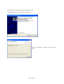
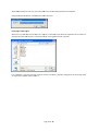
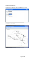
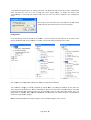
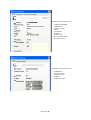
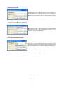
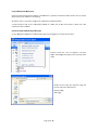
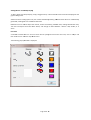
Site Survey Kid (SSK)
Re
ce
ive
r
Sontay® SonNet Radio Sensor Site Survey Tool User Manual Version 1.7 March 2011 Page 1 of 38 Audience This manual is intended for specifiers, users and installers of the Sontay® SonNet radio sensor system. Content This manual provides a complete reference for the Sontay® SonNet radio Site Survey system. Related Documents The Sontay® SonNet radio sensor system Site Survey Kit Quick Start Guide The Sontay® SonNet radio sensor system User Manual The Sontay® SonNet radio sensor system Quick Start Guide The Sontay® SonNet radio sensor system product datasheets Page 2 of 38 Table Of Contents: Overview ................................................................................................................................................................. 4 Environmental ........................................................................................................................................................ 4 Battery Charging ..................................................................................................................................................... 4 SSK Functional Overview ........................................................................................................................................ 5 Using the SSK .......................................................................................................................................................... 6 Verification Mode ............................................................................................................................................... 6 Battery Fitting and Replacement ............................................................................................................................ 8 Disposal of Batteries ............................................................................................................................................... 8 SSK Part Codes ........................................................................................................................................................ 8 SSK Nodes ............................................................................................................................................................... 9 SSK Node Specification ....................................................................................................................................... 9 SSK Routers ........................................................................................................................................................... 10 SSK Router Specification .................................................................................................................................. 10 The SSK Receiver ................................................................................................................................................... 11 SSK Receiver Specification ................................................................................................................................ 11 The SSK Hand Held Monitor ................................................................................................................................. 12 SSK HHM Specification ..................................................................................................................................... 12 The Radio Network ............................................................................................................................................... 13 Network Planning Considerations ........................................................................................................................ 14 The Radio System ................................................................................................................................................. 16 Security ................................................................................................................................................................. 16 How the Self‐Healing Tree Network Is Formed .................................................................................................... 16 Propagation Of Radio Signals In Buildings ............................................................................................................ 17 Attenuation ...................................................................................................................................................... 17 Reflection ......................................................................................................................................................... 17 Scattering ......................................................................................................................................................... 17 FAQs ...................................................................................................................................................................... 18 Using the SSK with SonNet Configuration and Monitoring Software (CMS) ........................................................ 19 Important – Windows 7 Users .......................................................................................................................... 19 Installing CMS ................................................................................................................................................... 21 Starting CMS ..................................................................................................................................................... 24 Importing a Saved Layout ................................................................................................................................. 25 The CMS Desktop Environment ....................................................................................................................... 26 Logging On as an Administrator ....................................................................................................................... 27 Changing the Administrator Password ............................................................................................................. 27 Listing Devices .................................................................................................................................................. 28 Changing Device Labels .................................................................................................................................... 29 Viewing Device Properties ............................................................................................................................... 30 Authorising a new node ................................................................................................................................... 32 Removing a node from the network ................................................................................................................ 32 Using the Graphical Map Display ..................................................................................................................... 33 Setting The Map Display Background Image .................................................................................................... 33 Adding Devices To The Map Display ................................................................................................................ 34 Icon Plan ........................................................................................................................................................... 34 Device Status .................................................................................................................................................... 35 Link Status ........................................................................................................................................................ 35 Auto Updating .................................................................................................................................................. 36 Manual Refreshing Of Data .............................................................................................................................. 36 Communications Log ........................................................................................................................................ 37 Configuration Log ............................................................................................................................................. 38 Page 3 of 38 Overview The wireless nodes are based on direct‐sequence spread spectrum (DSSS) communication in the 2.4 ‐ 2.5GHz band, compliant with IEEE 802.15.4‐2006. All nodes have a unique MAC address, equivalent to a unique serial number. All nodes have a PCB‐mounted on/off switch or jumper. All nodes retain their configuration properties across a power failure. Environmental • Storage temperature range of ‐10 to +80°C • Storage relative humidity range of 0 to 90% (non‐condensing). • Ambient (operating) temperature range of ‐10°C to +70°C • Ambient (operating) relative humidity range of 0 to 90%, (non‐condensing). Battery Charging To charge the battery in an SSK (site survey kit) node, connect the correct charger to the socket on the back plate. The status LED on the charger will show red until the battery is fully charged, when the status LED will turn green. To charge the battery in an SSK router, connect the correct charger to the socket mounted on the side of the housing. The status LED on the charger will show red until the battery is fully charged, when the status LED will turn green. NB ‐ the same charger type is used for both SSK nodes and SSK routers. To charge the battery in the HHM (hand held monitor), connect the correct charger to the socket located on the bottom of the housing. The status LED visible through the HHM keypad will show orange until the battery is fully charged, when the status LED will go out. To charge the battery in an SSK receiver, connect the correct charger to the charger socket. The status LED on the charger will show red until the battery is fully charged, when the status LED will turn green. Note that when charging SSK batteries, the electronics are disconnected from the rest of the device, and therefore that device will not function until charging is complete. Only the battery is connected to the charger. Only the correct chargers must be used for each SSK device. Batteries will be damaged if not charged by the correct charger. Page 4 of 38 SSK Functional Overview The Sontay® SonNet Site Survey Kit (SSK) is designed to make the design and installation of a SonNet radio sensor system simple and quick and to take the guesswork out of the radio communications aspect of the network. The SSK receiver should be placed where the actual RF‐RX system receiver will be installed (typically in a plant room or riser). The hand‐held monitor (HHM) communicates with the SSK receiver (via a router, if necessary), and the LCD display shows which nodes are on‐line and the quality of the radio link to their “parent” devices. Follow the step‐by‐step guide to determine where to position the receiver, any routers necessary, and to test that all sensor nodes can communicate with the receiver reliably when installed. The SSK is housed in a robust case, and contains: • 1 x SSK receiver • 1 x hand‐held monitor (HHM) • 4 x battery powered SSK sensor nodes • 2 x SSK routers • 1 x charger unit for the SSK receiver • 1 x charger unit for the HHM • 2 x charger units for the SSK nodes and routers SSK Quick Start Guide • • SSK User Manual Page 5 of 38 Using the SSK Place the SSK receiver where the final system receiver will be installed. Switch on the SSK receiver. Place SSK nodes where final system end device nodes will be installed. Switch on the SSK nodes. Switch on the HHM. The HHM displays all on‐line routers and sensors on the radio system. After initialisation, the LCD will display a list of devices which are connected directly to the receiver, together with their link quality index (LQI). Where a listed device is a router, to the right of that device will be a number which denotes the number of “children” the device has. To get further information about a device, use the Up/Down arrow keys to select that device, then press the right arrow key to view more detailed information. To display the MAC address and firmware revision number, use the right arrow key to select “more” then press the OK key. To go back to the main device list, use the Up/Down arrow keys to select “back”, then press the OK key. Verification Mode Verification mode is a special mode that an SSK node or router can adopt specifically to test the LQI to another device. In this special mode, the device ignores the normal hierarchical rules used to form a robust network, and relies solely on signal strength. When a device is requested to go into verification mode, it will briefly drop off the radio network and, having rebooted, reappear running in verification mode. Note that a device placed in to verification mode will automatically reboot back into normal mode after 5 minutes if left unattended. Power‐cycling a device in verification mode will also return that device to normal mode. To place a device in verification mode, select the device from the list by using the Up/Down arrow keys, then press the right arrow key. Using the Up/Down arrow keys to select “verify”, then press the OK key. The device will go off‐line for a few seconds, before re‐joining the network in verification mode. Switch off the HHM. 1. Ensure that the SSK receiver, HHM, and special battery powered SSK routers and nodes are fully charged. Always use the correct chargers provided to for each device. Batteries will be damaged if not charged by the correct charger. 2. Place the SSK receiver where the system receiver will be placed, ensuring that the aerial is aligned vertically if possible. 3. Switch on the SSK receiver. 4. Switch on the HHM. After a brief period, the LCD display will show the HHM in the device list. 5. Place the battery powered sensor nodes where required by the site specification, taking care to ensure that the sensors are not placed; a. In direct sunlight or near a source of heat b. On a cold or hot outside wall, where conducted or radiant heat may affect the reading c. Behind any obstruction likely to impede the radio signal (for example, a filing cabinet) Page 6 of 38 6. Using the HHM, observe whether each battery powered sensor node has communication back to the SSK receiver. If it does, observe the link quality, shown on the LCD display. a. b. c. d. e. f. g. 7. If the link quality is shown as good or v. good, no router is required for this node. Go to step 7. If there is no communication, or link quality is shown as marginal to the SSK receiver, you will need to position a router between the node and receiver. In this case, position a router between the node and receiver in a convenient location, remembering that a system router in the final installation will require a permanent 24Vac/dc supply. Observe the HHM again. The new router should be registered on the HHM. Using the HHM, observe the link quality for the new router to the receiver. If the link is shown as good, proceed to step 6f. If the link quality is shown as marginal, select the new router and then navigate to “Verification” on the HHM menu. Press the OK key to force the new router into verification mode. The node will go off‐line for a short period, then re‐join in verification mode. The router will now try to find a better communications path back to the receiver via another router, if there is one already installed. Note the link quality and the position of the router. It is recommended that a drawing or floor plan be used to mark device positions. Using the HHM, select the node and then navigate to “Verification” on the HHM menu. Press the OK key to force the new node into verification mode. The node will go off‐line for a short period, then re‐join in verification mode. Note the link quality and the exact position of the router. Where a router or node has been placed into verification mode, it must be returned to normal operating mode by resetting or power cycling prior to moving to step 7. If left unattended for more than 5 minutes, a router or node placed into verification mode will automatically return to normal mode. Continue placing battery powered sensor nodes (and routers if required), until battery powered sensor nodes have been tested at the required points, good quality links are shown for all devices on the HHM, and complete coverage is demonstrated. Notes: • • • In the final installation, routers can also be sensors. However, they require a permanent 24Vac/dc supply. Each router can support a maximum of 16 “children”, which can consist of a maximum of 8 battery powered nodes and 8 routers, or up to 16 routers if there are no battery powered end devices (EDs). In most circumstances, it is advised that, unless unavoidable, no more than 8 “children” should be connected to a single router, to allow for redundancy in case of router failure or damage. SSK nodes are fitted with a thermistor temperature element, and will report temperature and battery status to the HHM or CMS (configuration and monitoring software). SSK routers are not fitted with temperature sensing elements, and will only report link qualities and battery status. Page 7 of 38 Battery Fitting and Replacement When a battery is first installed, or when it is replaced, observing the correct polarity is very important. Fitting the battery incorrectly may result in permanent damage to the sensor. Recommended batteries are: Nodes and routers: 3.7V Lithium Polymer, rechargeable 1080mAh (Uniross U0110952) Hand Held Monitor (HHM): 3.6V NiMH, rechargeable 580mAh (Varta 3/V600HR WIRE) SSK Receiver: 12V NiMH, 2100mAh, 10 x AA cell rechargeable pack (Strikalite 752) Batteries should be stored in a clean, cool (not exceeding +30°C), dry and ventilated area. Disposal of Batteries ‐ Warning! Fire, Explosion and Burn Hazard Do not short‐circuit, crush, disassemble, heat above 100°C (212°F), incinerate, or expose the battery contents to water. Do not solder directly to the cell. All batteries must be disposed of in accordance with EC Directive 2006/66/EC, amended by EU Directive 2008/12/EC. SSK Part Codes: RF‐SSK – Site Survey Kit RF‐RXSS ‐ Receiver module (no outputs) RF‐HHT ‐ Handheld monitor RF‐TS‐900 ‐ Temperature SSK sensor RF‐PS‐500 ‐ SSK Router Page 8 of 38 SSK Nodes RF‐TS‐900 nodes are used in conjunction with the Sontay® RF‐RXSS receiver, RF‐PS‐500 routers and RF‐HHT hand held monitor. Data is transmitted back to the receiver every 30 seconds. Each sensor retains these configurations if the battery becomes discharged or requires replacement. NB ‐ To preserve battery life, an SSK node will automatically go off‐line after approximately 4 hours if not power‐cycled. To charge the battery in an SSK node, connect the correct charger to the socket on the back plate. The status LED on the charger will show red until the battery is fully charged, when the status LED will turn green. To power an SSK node, the battery must be connected and the On/Off rocker switch on the backplate should be switched to the On position. To switch off, the On/Off rocker switch on the backplate should be switched to the Off position. Refer to datasheet. The sensors automatically find the best path back to the receiver, which may be directly to the receiver or via “parent” routers. • SSK nodes have a thermistor temperature sensor fitted as standard. SSK Node Specification: Radio Output: Frequency 2.4GHz 16 channels, automatically selected Direct‐sequence spread spectrum Compliance IEEE 802.15.4‐2006 Aerial Characteristics Gain 1.2dBi VSWR 1.5:1 Data Encryption: AES 128 Power Output: 0dBm Temperature accuracy ±0.3°C Battery Type: 3.7V Lithium Polymer, rechargeable, 1080mAh Housing Material: ABS (flame retardant) Dimensions: 85 x 85 x 23mm Environmental: Operating: Temperature ‐10°C to +50°C RH 0 to 90%, non‐condensing Storage: Temperature ‐10°C to +80°C RH 0 to 90%, non‐condensing Country of origin: UK Part Code: RF‐TS‐900 Refer to product datasheet for installation instructions. Page 9 of 38 SSK Routers RF‐PS‐500 SSK routers are used in conjunction with the Sontay® RF‐RXSS receiver, RF‐TS‐900 nodes and RF‐
HHT hand held monitor, and are used to route signals from battery powered nodes and other routers to the receiver module, where the signal strength of a direct path is not sufficient for reliable communications. NB Each router can support a maximum of 16 “children”, which can consist of a maximum of 8 battery powered nodes and 8 routers, or up to 16 routers if there are no battery powered end devices (EDs). Consideration should be given on network planning for redundancy in case of router failure or damage. Routers automatically find the best path back to the receiver, which may be directly to the receiver or via other “parent” routers. NB To preserve battery life, an SSK router will automatically go off‐line after approximately 4 hours if not power‐cycled. To charge the battery in an SSK router, connect the correct charger to the socket mounted on the side of the housing. The status LED on the charger will show red until the battery is fully charged, when the status LED will turn green. NB ‐ the same charger type is used for both SSK nodes and SSK routers. To power an SSK router, the battery must be connected and the On/Off toggle switch on the housing side should be switched to the On position. To switch off, the On/Off toggle switch on the housing side should be switched to the Off position. Refer to datasheet. • SSK routers do not have a temperature sensor fitted. SSK Router Specification: Radio Output: Frequency 2.4GHz 16 channels, automatically selected Direct‐sequence spread spectrum Compliance IEEE 802.15.4‐2006 Aerial Characteristics 2.0dBi Gain VSWR <2:1 Data Encryption: AES 128 Power Output: +10dBm Battery Type: 3.7V Lithium Polymer, rechargeable, 1080mAh Housing: Material ABS (flame retardant type VO) Dimensions 55mm x 90mm dia. Mounting holes 4mm spaced 85mm apart Environmental: Operating: Temperature ‐10°C to +50°C RH 0 to 90%, non‐condensing Storage: Temperature ‐10°C to +80°C RH 0 to 90%, non‐condensing Country of origin: UK Part Code: RF‐PS‐500 Refer to product datasheet for installation instructions. Page 10 of 38 The SSK Receiver The Sontay® RF‐RXSS receiver collects data from all other devices on the SSK radio network, including measurements from sensors, link quality for all links formed in the network, battery levels for all battery powered devices, hours run for all devices and the current status of all devices. NB There are no analogue outputs on an RF‐RXSS. The SSK receiver is used solely to determine signal strengths and whether routers need to be added to a network to achieve complete, reliable coverage. Data is transmitted back to the receiver at pre‐configured time intervals. A USB socket is provided for connection to a PC or laptop running the Sontay SonNet CMS software. To power the SSK receiver, turn the On/Off switch on the housing cover to ON. To switch off, turn the On/Off switch on the housing cover to OFF. To charge the battery in an SSK receiver, connect the correct charger to the socket. The status LED on the charger will show red until the battery is fully charged, when the status LED will turn green. SSK Receiver Specification: Radio Output: Frequency 2.4GHz 16 channels, automatically selected Direct‐sequence spread spectrum Compliance IEEE 802.15.4‐2006 Aerial Characteristics Gain 2.0dBi VSWR <2:1 Data Encryption: AES 128 Power Output: +10dBm Power Supply: Internal 12Vdc NiMH battery, 2.1Ah Serial communications: USB 2.0 Environmental: Operating: Temperature ‐10°C to +50°C RH 0 to 90%, non‐condensing Storage: Temperature ‐10°C to +80°C RH 0 to 90%, non‐condensing Country of origin: UK Part Code: RF‐RXSS Refer to product datasheet for installation instructions. Page 11 of 38 The SSK Hand Held Monitor The Sontay® RF‐HHT displays all on‐line receivers, routers and nodes in the SSK radio network, and shows link quality for all links formed in the network, battery levels for all battery powered devices, hours run for all devices and the current status of all devices. To switch on the HHM, press and hold the OK key for approximately 1 second. To switch off, press and hold the OK key for at least 2 seconds. The HHM will beep to indicate that it is shutting down. To charge the battery in the HHM, connect the correct charger to the socket located on the bottom of the housing. The status LED visible through the HHM keypad will show orange until the battery is fully charged, when the status LED will go out. SSK HHM Specification: Radio Output: Frequency 2.4GHz 16 channels, automatically selected Direct‐sequence spread spectrum Compliance IEEE 802.15.4‐2006 Aerial Characteristics Gain 2.0dBi VSWR <2:1 Data Encryption: AES 128 Power Output: +10dBm Power Supply: Internal 3.6Vdc NiMH battery, 580mAh Environmental: Operating: Temperature ‐10°C to +50°C RH 0 to 90%, non‐condensing Storage: Temperature ‐10°C to +80°C RH 0 to 90%, non‐condensing Country of origin: UK Part Code: RF‐HHT Refer to product datasheet for installation instructions. Page 12 of 38 The Radiio Network d sensors and permanentlyy powered A Sontayy® SonNet radio system is comprised of aa receiver, batttery powered
routers. manently pow
wered, can aalso have sen
nsing elementts, accomplisshing both ro
outer and Routers, though perm
uters and senssors can eitheer communicaate directly with the receiveer or via othe
er routers. sensors ffunctions. Rou
Routers aare required to be perman
nently powerred as they ne
eed to stay “a
awake” at all times to allo
ow signals from “ch
hild” nodes to
o be instantly forwarded too their “paren
nt” nodes. Battery powereed sensors only “wake” for very sshort periods to send data. hematic above, router R4 h
has 3 children,, all battery powered senso
ors. It’s parentt is R2. Router R2 has 4 In the sch
children, 3 battery po
owered senso
ors AND R4. R2’s parent is i R1, which has 6 childreen, 4 battery powered sensors, R2 and R3. um of 16 direcctly connected
d “child” devicces, of which only 12 can b
be battery The receiver can support a maximu
d nodes, plus u
up to 4 routerrs. Routers cann support a m
maximum of 16
6 directly con nected “child” devices, powered
of which only 8 can bee battery powered nodes, pplus up to 8 ro
outers. There can be a maxiimum depth o
of 8 layers work and a maaximum of 50 nodes per ne twork with th
he RF‐RX series of receiverss. in a netw
NB From the receiver to router R1 ccan be consideered as a “layyer”. Page 13 of 38
8 Note that battery pow
wered devices can only routte their signals to the receiver directly oor through rou
uters, and ugh other batttery powered devices. not throu
Net radio netw
work, it is recoommend thatt the Sontay® SonNet Site SSurvey Kit be u
used. This When plaanning a SonN
easy‐to‐u
use package aallows installe
ers to test signnal strengths between loca
ations requireed for batteryy powered sensors aand the receivver prior to in
nstalling the ffull system. It can also iden
ntify whether routers are n
needed to ensure reeliable comm
munications be
etween all deevices on the network back
k to the receiiver. This rem
moves any guesswork from plann
ning a system and allows th e installer to order exactly and only the devices required. Net radio senssor system Sitte Survey Kit Quick Start Guide and Thee Sontay® Son
nNet radio See the SSontay® SonN
sensor syystem Site Surrvey Kit Manu
ual for full detaails. nsiderations Networkk Planning Con
nNet radio syystem, it is aalways worth considering the placemennt of routerss. Routers When pllanning a Son
support aa maximum of 16 children, be aware of tthe consequences of a routter failing or bbeing damaged. Example:: h
2 This network has b
routerrs and 16 battery powerred sensors (8 per routerr) If routter R2 failed or was damagged, there would not bee enough capaacity in the ro uter R1 to taake the ors. 8 “orp haned” senso
hat at least 8 “orphaned” ssensors would
d not be able to find a routte back to the
e receiver, The result would be th
R2 was replace
ed. and would go off‐line until their origginal parent R
Page 14 of 38
8 This netw
work has 4 rou
uters and 16 b
battery powerred sensors (4
4 per router)
was damaged in this scenar io, there would be enough capacity in roouters R1, R2 and R3 to If router R4 failed or w
take the 4 “orphaned”” sensors. hat all 4 “orphaned” sensoors would still be able to fin
nd a route baack to the rece
eiver, and The result would be th
R4 was replace
ed. would reemain on‐line until their origginal parent R
Page 15 of 38
8 The Radio System The radio system used by the Sontay SonNet devices is divided into 3 sections or ‘layers’. 1. The radio layer is where physical control of the radio signal is done. This conforms to international standard 802.15.4, and determines the frequency of the radio signals, the number of ‘channels’ available for use, the bandwidth and power level of the signal etc. There are 16 channels available, and the best one is automatically selected by the receiver. The frequencies used are in the ISM (Industrial, Scientific and Medical) 2.4GHz band, with a maximum data rate of 250kb/s. 2. The network management layer is where the self‐healing tree functionality is run, which controls network topology. ‘ZigBee’ is an example of a network management MESH protocol. SonNet does not use ZigBee, but instead uses a ‘self‐healing tree’ protocol to control network topology. 3. The application layer is what determines what the device does – i.e. makes it a temperature sensing device, a router or a receiver. SonNet devices use specific applications, and include features such as configuration properties. Security All SonNet system devices have the same, unique network identifier. Only devices with the correct ID will be allowed to join the network. The ID used by system devices is different from the ID used for site survey kit (SSK) devices. Hence, SSK devices cannot join a system network and vice versa. When a SonNet system network has been formed, it can be ‘locked’ to prevent any unauthorised devices joining, even if they are SonNet devices. The CMS can be used to authorise extra SonNet system devices if required. All data transmitted by SonNet devices is encrypted. How the Self‐Healing Tree Network Is Formed The network is formed based on 3 rules, and in a specific order of priority: 1. How many ‘tiers’ a device is away from the receiver. If a device can communicate directly with the receiver, it will, even if the link quality is poorer than if it went through a router. If a device has a choice of more than one router, it will always choose the router closest to the receiver (the least number of tiers away), even if the link quality is marginal. 2. The number of ‘child’ devices a router already has. A router can have a maximum of 16 ‘children’. If a device has a choice of more than one router of the same tier level, it will always choose the router with the least number of children, even if the link quality is marginal. 3. Signal Strength (link quality). Finally, if a device has a choice of more than one router of the same tier level and the same number of children, it will choose the router with the best link quality. If, for any reason, a device (node or router), loses its preferred path back to the receiver, it will automatically search for an alternative – still obeying the 3 rules above in sequence. If, despite employing Direct Sequence Spread Spectrum (DSSS) techniques, interference on the currently occupied channel prevents communications, the receiver will automatically look for another channel which is clear. All other devices, having lost their links to the receiver, will then also automatically scan the 16 channels until they find the receiver again, and the network will re‐form without user intervention. Page 16 of 38 Propagattion Of Radio Signals In Buildings pagation of miicrowave radio signals in a building can b
be affected in several ways : The prop
Attenuattion Radio signal sttrength is attenuated whe
en it passes thhrough air. Signals are atttenuated muuch more whe
en passing through other m
media, such as materials tyypically used in constructtion, such as brick, stone,, wood and especially stteel. on Reflectio
epending on the building, radio signals can take many paths from the De
tra
ansmitter to tthe receiver, rrather than just one single ppath. Multipath’ signnals can have the effect of cancelling eaach other out,, reducing ‘M
ovverall receivedd signal strenggth. ng Scatterin
ng the radio siggnal can also reduce it’s siggnal strength.
Scatterin
8 Page 17 of 38
FAQs a. How is access to the sensor network locked at the CMS? Nodes are only allowed to join the network if the receiver allows them to. This is true even if the nodes are identified as SonNet Nodes and have the correct encryption key. There are two methods to configuring the receiver to accept nodes on to the network. In order to authorise a node the CMS must be in administration mode (File‐>Switch Admin Mode must be ticked). • Auto‐Commissioning Mode The CMS allows the receiver to be switched to auto‐commissioning mode. In this mode any nodes that can correctly identify themselves as SonNet nodes will be allowed to join the network. Any nodes that do join will be added to the CMS textual display. • Manual Mode In manual mode individual nodes can be removed from or added to the authorised node list from the CMS. Manual mode is the default mode. A node can then be authorised by Options‐>Authorise (add) a new node or selecting the same option on the right click menu in the Textual or Graphical parts of the application display. The user must type the MAC address (on PCB and product housing) of the new node into the dialog that appears and can also give the node a textual name (up to 10 characters) b. Why do some menu items disappear if the CMS application is idle for some time? The CMS has a timeout that operates when in Admin mode. If there is no activity for some time the CMS application will exit admin mode and some admin menu items will be disabled or removed. The timeout can be set in Options‐> Change Idle Time. Admin mode can be entered again in File‐>Switch Admin Mode c. The CMS application right click menu has stopped being provided. Why? This probably means that the CMS has detected that the receiver has been disconnected from the PC. This will be indicated on the status bar at the bottom left side of the CMS application window "Receiver Disconnected". In this state many of the CMS facilities are disabled until the Receiver is connected again. d. How are the network node names stored, are they persistent? The node names are stored in the receiver hardware in non‐volatile memory. Therefore these will be the same even if a different PC is attached to the system, or the receiver is reset / power cycled. e. In the CMS application what is an Unknown node? The application will list all nodes that have been added to the system as unknown initially. As soon as a node is added (either manually or by the use of auto commissioning mode) a request is sent to it to establish what type of node it is and what capabilities it has. As a result a node will be categorized as unknown until a response is received from it. If the node remains off‐
line or does not respond for any other reason it will remain in this category. The CMS will send a request each time it is started if there are still unknown nodes in the system. Page 18 of 38 onNet Configu
uration and M
Monitoring Sofftware (CMS)
Using thee SSK with So
h not necessary to undertake a site survvey, CMS can be used with
h the SSK if reequired. Afterr installing Although
CMS (seee user manuaal), connect the SSK receivver to a free USB port on the CMS PCC. After the drivers are installed,, CMS can be used to textually and graphhically displayy the SSK netw
work. It can be used for; • Addiing or removing nodes1 • Provviding a text and graphical ddisplay of the network • Mon
nitor device status • Mon
nitor link and b
battery qualitty • View
w logs for rece
eiver configuraation changess 1
All nodes, router and the HHM are pre‐config ured into the
e SSK receiverr. No further aauthorization of nodes m devices can not be authorrized in an SSK
K receiver. should bee needed. Note that system
procedure insttalls 3 componnents: The CMSS installation p
• Micrrosoft® SQL Se
erver 2005 Ex press Edition SP2 • Sonttay® SonNet C
CMS • Sonttay® device USSB device drivvers mportant thatt the CMS insttallation be coompleted prio
or to connectin
ng the PC to tthe receiver. NB It is im
nt – Windowss 7 Users Importan
Prior to installing CMSS, it is important to turn off driver signingg. e in the searchh bar. Right cliick on cmd.exe and choose e run as admin
nistrator. From thee Start menu, type cmd.exe
Page 19 of 38
8 Run the ffollowing com
mmands in the
e shell. options DDISABLE_INTEGRITTY_CHECKS bcdedit.eexe ‐set loado
bcdedit.eexe ‐set TESTSSIGNING ON ollowing will bbe displayed in
n the bottom right corner oof the desktop
p: Restart the PC. When logged, the fo
osoft® SQL Se
erver 2005 Exxpress Edition SP2 is installed first, if not already installed, Micro
follow
wed by Sontayy® SonNet CM
MS and finally tthe Sontay® d
device USB devvice drivers. n issue with SQL Server 22005 Express Edition SP2 and MSXML 6 SP2 (see Microsoft Note thaat there is an
Knowledge Base articlle KB954459 ffor full detailss). To overcom
me this, the C
CMS installatioon will offer tto run the When this message appearrs, click on the
e <Install> Windowss Installer Cleanup Utility to uninstall M SXML6 SP2. W
button. Page 20 of 38
8 Installingg CMS NB N It is important that thhe CMS installation be completed prior to conneecting the PC to the re
eceiver. Ensu
ure that the PC on which
h you are in
nstalling CMS is NOT connnected to the
e receiver until the instal
u
lation is compplete. CMS C
is compa
atible with M
Microsoft® Win
ndows XP SP2 or later, Microsoft® Vista and Microsoft® M
Windows W
7. The CMS instaallation CD co
omes with all required programme p
ffiles and drivvers, and ncludes SQL Server 2005 Exxpress Edition SP2. in
NB N You must be logged inn to Windowss with an administrator level user acccount to install CMS and SQL Server 2005 Expresss Edition SP2. P2 is not Iff SQL Server 2005 Expreess Edition SP
already installed on youur PC, the following nstallation will be executedd. in
When W
the SQL Server 20005 Express Ed
dition SP2 in
nstallation window appearrs, read the EULA and th
hen click the <
<Accept> buttton. QL Server 20005 Express Ed
dition SP2 The installation of SQ
continuess until complete. The next step in the installation proocedure will display the nNet CMS Seetup Wizard. Click the “Welcome to the Son
utton to contiinue. <Next> bu
Page 21 of 38
8 Click <I A
Agree> and theen the <Next>
> button to coontinue. d to your PC. SonNet files are copied
Page 22 of 38
8 Device drrivers are required for the USB receiver cconnection. To installl these, click the <Next> button to continnue. n the installattion is compllete, click the
e <Close> When
button. Page 23 of 38
8 Starting C
CMS he receiver is first connected to a USB port and swittched on, the
e device manaager will dete
ect a new When th
device. Follow these stteps to install the drivers foor the receive
er. Select the opt
S
ion shown (“N
No, not this tim
me”) Select S
the op
ption shown (“Install the software automatically”
a
”) If advised that the drivers havee not passed Windows esting, or are not digitally ssigned, click ““Continue Logo te
Anyway” me procedure
e for both drivers. There aree 2 drivers to be installed, ffollow the sam
Page 24 of 38
8 When CM
MS is started, the PC com port connectedd to the receivver USB port n
needs to be d efined. Using thee drop‐down llist box, selectt Wireless Sennsor Receiver.. ng a Saved Layyout Importin
may also ask iff the user requuires a saved XML layout file to be imporrted. This is useful if an When first run, CMS m
existing layout has beeen saved on a site where thhe PC running CMS has been replaced. out file is required, click th
he <Cancel> b utton to conttinue, otherwise navigate tto the saved llayout file If no layo
to and click the <Open
n> button imp
port it. 8 Page 25 of 38
The CMSS Desktop Envvironment parts, a textuaal hierarchical display The CMSS desktop is divvided into 2 p
and a graaphical “map”” display. 8 Page 26 of 38
display panel, from the meenu bar choosse <View> To enaable the text d
then <TTextual Displaay> phical display panel, from the menu ba
ar choose To enaable the grap
<View>> then <Graph
hical Display> On as an Adm
ministrator Logging O
es to device cconfiguration or to create or modify To makke any change
the gra phical displayy, you must firrst log on as aan administrattor. To do File> then <Sw
witch Admin M
Mode> this, froom the menu bar choose <F
TThe login box appears. Type in your adm
min level passsword. NB TThe default admin a
level password p
is aadmin (case sensitive). s
TThis can be changed once you have loggeed in. Changingg the Adminisstrator Password TTo change the
e admin passsword, from the menu ba
ar choose Change Passw
word>. Enter tthe existing password, p
< File> then <C
ew password and confirm
m. Click the <Update> e nter your ne
mit the change
e, or click <Caancel>. bbutton to subm
8 Page 27 of 38
To preveent leaving th
he CMS in an admin state when not su
upervised, the
e admin log‐iin status auto
omatically times ou
ut after the time set in the “Changee Idle Time”” setting exp
pires. To disaable this feature (not recommeended), or to
o change the timeout valuue, from the menu bar choose <Optionns> then <Ch
hange Idle Time> Rem oving the tick the Enable Idle Time Ouut box disablles admin timeeout feature. TThe timeout value can also be changed. Listing Devices In the teext display panel on the lefft of the winddow, a list of all devices on the networrk can be found. These devices aare divided intto 3 main cate
egories, receivver, routers and battery powered sensorr nodes. Each cateegory can be eexpanded to vview more dettail or collapsed to hide detail. w
are join
ning the netw
work for the first f
time, The “Unkknown” categgory is initiallly populated by devices which either byy auto‐commiissioning or m
manual authorrization. Devices are held in the unknow
wn category until CMS has determined the tyype of device trying to join (for example
e, a router or node) and whhich options, iif any, are uch as setpoin
nt). When CM
MS has determ
mined this infformation, the device will then automa
atically be fitted (su
placed in
n it’s appropriaate category. hand held mon
nitor will onlyy ever appear in the Unknow
wn category. T
This is norma l. NB The h
Page 28 of 38
8 Changingg Device Labe
els n the CMS, haas a default laabel, such as ““Router1” or “Sensor2”. To
o give the Each devvice, when firsst depicted in
router a more meaningful label, righ
ht click on thee router and cchoose <Prope
erties> In the <Naame> box, tyype in the new namee you require
e and click the <Channge> button. NB There is a limit off 10 ASCII ames. characterss for router na
ose <Propertiees> To give a sensor a morre meaningfull label, right c lick on the sensor and choo
In the <Naame> box, tyype in the new namee you require and click the <Changge> button. NB There is a limit of 10 ASCII ames. characterss for sensor na
8 Page 29 of 38
Viewing Device Prope
erties To view the current analoogue output channel ppings, expand
d the receiverr in the text diisplay. map
e specific prop
perties of anyy device can b
be viewed The
by right‐clicking a device and selecting <Prroperties> n menu. in the drop‐down
Avaailable router properties aree: Parent (if app
plicable) MAC addresss Software version Status Link Quality
Runtime arms Any active ala
Page 30 of 38
8 Available sensor propperties are: ent (if applicabble) Pare
MAC
C address Software version Status Link Quality Runttime Battery level Any measured va lues Any active alarmss e receiver prooperties are: Available
C address MAC
Software version RF channel used Runttime Auth
horised nodess Page 31 of 38
8 Authorising a new nod
de TTo manually authorise a
a ne
ew node(s), yyou must be logged l
on aat administrattor level. From
m the menu bbar, click on <
<Options> aand then selecct <Authorise (add) a new node> from the drop‐
ddown menu.
need to makee a note of the unique 16‐ddigit MAC add
dress of the new node, fouund on the lab
bel on the You will n
device. Ensure the new
w device is po
owered on. EEnter this MAC
C address and
d a device labbel into the ap
ppropriate bbox fields an
nd click <OK> to submit the details,, or click <<Cancel> to discard the info
ormation. ng a node from
m the network Removin
e network, froom the menu bar, click Too remove a node from the
onn <Options> and then select <De‐authhorise (removve) node> frrom the drop‐‐down menu. Select the deevice group (rrouters or hen select the device by nam
me (label). seensors) and th
bmit the detaiils, or click <Caancel> to disccard the action
n. Click <Reemove> to sub
Page 32 of 38
8 Using thee Graphical M
Map Display om the text hiierarchical dissplay, the CMSS offers a graphical environ
nment which allows users to quickly Apart fro
determin
ne how the neetwork is functioning. e map display. By default, there is no graphic imagge set as a bacckdrop for the
ap display woould be a flo
oor plan of th
he environmeent in which the radio A typicall image to usse for the ma
network has been insttalled. nd Image Setting TThe Map Displlay Backgroun
background im
mage for the m
map display, yyou must be lo
ogged on at administrator llevel. To set a b
m the menu bar, click onn <Options> and then From
sele
ect <Set Backg
ground Imagee> from the drop‐down men
nu. Browse to the image fille required. Image file formats currrently supporrted are: mp) Bitmap (.bm
JPEG (.jpg)
Page 33 of 38
8 Adding D
Devices To The
e Map Displayy To add a device to thee map display, simply “dragg‐and‐drop” a device from tthe text hierarrchical displayy onto the background. graphic b
he graphic first, then routerrs followed byy battery pow
wered nodes. LLinks are auto
omatically Add the receiver to th
generateed, showing th
he true netwo
ork architecturre. Differentt icons are useed to depict the receiver, rrouters and battery powere
ed node, makking identification easy. The icons also depict the status off the device, and change to reflect whether a devicce is OK, off‐lline, or in alarm. n Icon Plan
ule of what eaach icon and icon colour ccan be quicklyy found from the menu baar, click on <H
Help> and A schedu
then seleect <Icons> fro
om the drop‐d
down menu.
window is displayed: The following pop‐up w
Page 34 of 38
8 Device Sttatus n be made by hovering the mouse cursor over a devicce on the map
p display. A quick ccheck on a devvice status can
parameters are device depeendent, but in
nclude: Displayed p
me (label) Device nam
All sensor vvalues Battery leve
el (battery devices only) NB Wherre link quality, hours run an
nd battery levvel are shown in italics, this denotes thatt a request for data has been sen
nt to a device, but the devicce has not yett responded.
Link Stattus hically by the ccolour of the link drawn. The link sstatus is repreesented graph
tes good link quality. Green: Indicat
G
Red: Indicatess marginal link quality. o any link sttatus can be made by hovvering the A quick check on moouse cursor over a link on tthe map displaay. 8 Page 35 of 38
Auto Upd
dating ate at a user c onfigurable raate. The CMSS can be configgured to upda
ns> and then sselect <Changge Update From the menu bar, click on <Option
Time> froom the drop‐d
down menu. A
Adjust the uppdate time accordingly. Click <OKK> to submit the change,, or click <Caancel> to disscard the change. dating can also
o be disabled.. Auto upd
ns> and then sselect <Changge Update From the menu bar, click on <Option
Time> froom the drop‐‐down menu. Remove thee tick from the <Auto Update> box. Click <O
OK> to submit the changee, or click <Cancel> to discard thhe change. Refreshing Off Data Manual R
ually refreshedd. This is an im
mportant featture when re‐‐connecting th
he CMS to Node or network dataa can be manu
ng network. an existin
he CMS to a re
eceiver on an existing netw
work, data When re‐cconnecting th
will only be refreshed to the CMS as and whenn a device up
pdates it’s informatioon by timed transmission.
s
as soon as possible, use the Refresh Node To ensuree all data is sent Informatioon or Refresh Network Info
ormation optioons. hen select To manuaally refresh node data, right click on a node and th
<Refresh N
he drop‐downn menu. Node Informaation> from th
etwork data, right click on a blank spacce (on the To manuaally refresh ne
text or graphical display) d
and then selecct <Refresh Network menu. Informatioon> from the drop‐down m
8 Page 36 of 38
Commun
nications Log a log of all co
ommunicationns on the ne
etwork. This can be helpfful in finding faults or The CMSS can keep a diagnosin
ng network prroblems. unications logg is enabled. Iff you want to disable this fe
eature, By default, the commu
ptions> and tthen select <Configure From thee menu bar, click on <Op
Communnication Log> ffrom the drop
p‐down menu . Remove the
e tick from > box. Click <OK> to su
ubmit the the <Enaable Communication Log>
change, oor click <Cancel> to discard the change. e <View> then
n <Communicaations Log>. A
A window To view tthe communiications log, from the mennu bar choose
will appeear at the botttom of the m
main CMS win dow. To close
e this view, click the cross in the top rigght of the communications log w
window. 8 Page 37 of 38
Configuration Log u
to view a concise lisst of any changes made too the configu
uration of The conffiguration logg allows the user devices. TTo view the co
ommunications log, from t he menu bar choose <View
w> then <Conffiguration Logg>. ow only speci fic “key fieldss” such as when a configurration was changed, or Results sshow can be ffiltered to sho
analoguee output mapp
pings. Results can also be filttered within a user‐definabble date range. 8 Page 38 of 38