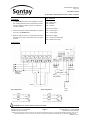
1
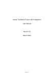
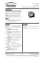
Data Sheet Ref: 90501161
Issue: 5.2
RE-PR3-E-36/54
36 & 54kW 3-Phase panel mount, heater controller
www.sontay.com
Technical Overview
The RE-PR3-E-xx are a range Thyristor control assemblies
that provides full seamless control of 3-phase resistive loads
of up to 36 & 54kW, using two thirds control technique. They
are controlled by a 0-5Vdc, 0-10Vdc signal or manual 5KΩ
pot.
This burst fire control assemblies use fast pulse, zero volt,
switching technology to minimise flicker and eliminate RFI
problems.
They also incorporate a temperature trip, automatic reset,
alarm output, LED ’output on’ indication and heatsink.
Applications include electric heater batteries and dust heaters.
Features
•
•
•
0-5Vdc, 0-10Vdc or manual 5KΩ pot control input
Over temperature protection with auto reset
No additional heatsinks required
Specification
Product Codes
Input signal
0-5Vdc, 0-10Vdc or manual 5KΩ pot
Supply (control)
24Vac/dc ±10% (by dipswitch)
Supply (load)
3-Phase 400V RMS ±10% 50/60Hz
Power /current ratings:
RE-PR3-E-36
Panel mount 3-phase 36kW electric heater controller
RE-PR3-E-54
Panel mount 3-phase 54kW electric heater controller
RE-PR3-E-36 36kW (50A per phase)
RE-PR3-E-54 54kW (75A per phase)
Fusing:
RE-PR3-E-36 56A H/S semiconductor (integral)
RE-PR3-E-54 80A H/S semiconductor (integral)
Terminal connections:
Auxiliary alarm Rising cage for 2.5mm² cable max.
Control
Rising cage for 2.5mm² cable max.
Power:
RE-PR3-E-36 Rising cage for 10mm² cable max.
RE-PR3-E-54 Rising cage for 16mm² cable max.
Terminal torque settings:
RE-PR3-E-36 2Nm (power terminals only)
RE-PR3-E-54 2.5Nm (power terminals only)
Over temperature:
Trip in temp.
@ 90°C ±1°C
Trip out temp. @ 85°C ±1°C
Fault condition
Relay rated at 230Vac @ 8A
Fault status:
Phase loss
LED flashes in 1.5 sec. pulse bursts
Sensor loss
LED flashes in 0.5 sec. pulse bursts
Ambient temperature
65°C (maximum operational)
Dimensions (L, W, H):
RE-PR3-E-36 205 x 155 x 120mm
RE-PR3-E-54 250 x 155 x 120mm
Conformity
CE Marked
Country of origin
UK
International Tel: +44 1732 861225
UK Sales Tel: 0845 345 7253
Page 1
International Fax: +44 1732 861226
UK Sales Fax: 0845 345 7353
Whilst every effort has been made to ensure the accuracy of this specification, Sontay cannot accept responsibility for damage, injury, loss or
expense resulting from errors or omissions. In the interest of technical improvement, this specification may be altered without notice.
90800066 Issue 1
Data Sheet Ref: 90501161
Issue: 5.2
RE-PR3-E-36/54
36 & 54kW 3-Phase panel mount, heater controller
www.sontay.com
SAFETY REQUIREMENTS & ADVICE SHEET
Introduction
Fusing
The objective of this leaflet is to provide information to en-
We recommend that semiconductor, fast acting to BS88 IEC
sure that the safety of the person(s) installing or maintaining
269, type fuses or circuit breakers (Semiconductor - MCB)
the equipment is not compromised and its location and
should be used for unit and/or device protection. The appro-
method of installation does not endanger others, either dur-
priate maximum load current should be known to select the
ing or after installation.
required SCR fuse or MCB, but must not exceed the equip-
Customers should be aware of the Health and Safety at
ment rating. The I² t (A² s) rating of the selected fuse must
Work Act 1974 (HSW 1974) and the EC “Provision and Use
be less than that of the equipment so as to protect the equip-
of Work Equipment Regulations 1992” (PUWER). Both are
ment’s discrete device. Further appropriate fusing may be
available from the Health and Safety Executive (HSE) publi-
required for protection of the unit supply using standard fuse
cations, within the UK.
links and holders. Failure to address these requirements
and the use of incorrectly selected fuses may cause the
Installation
equipment to fail.
CE Directives
Earthing
These are European regulations which apply to our industry.
The protective conductor terminal of the equipment must be
They affect the equipment emissions and immunity to Radio
utilised at all times and bonded to a ‘good’ Earth (ground).
Frequency Interference (RFI) and various elements of safety
The earth bonding (strapping) leads of any combined equip-
for electrical equipment.
ment should be as short as possible and be substantial, i.e.
The European Community ‘CE’ Directives that mainly con-
at least rated higher than the equipment’s load. For further
cern Sontay Ltd are, the Low Voltage Directive (LVD) and
information, refer to BS7671. Following these simple guide-
the Electromagnetic Compliance Directive (EMC).
lines will ensure optimum use of any appropriate filter cir-
A Declaration of Conformity may be supplied with the prod-
cuits which may be required.
uct or supplied on request.
Insulation (over-voltage category) and Protection from
Torque Settings
electric shock Classification of Equipment
Good working practises must be adhered to ensuring appro-
All equipment, unless otherwise stated, is rated to CLASS II
priate electrical and mechanical installation. This would in-
Insulation (Over-voltage category) and CLASS I (Protection
clude the mechanical fixing of potentiometer bushes and
category).
electrical set screw and/or pillar connections. These Electrical Connections and Mechanical Fastenings must not be
Maintenance
over tightened. We would recommend a typical torque set-
Before any servicing is carried out, reference should be
ting of 1 to 5Nm. For specific product information, see ap-
made to appropriate installation instructions, drawings and
propriate product data sheet, where applicable.
labelling which may come with the equipment. Personnel
should switch off the unit supply before accessing or removing any safety cover and be aware of hazardous live parts.
Cooling Requirements
The use of an additional heatsink (this could be a conductive
panel) suitably attached or mounted with the unit, will help to
dissipate heat away from the device(s). An alternative or
additional method would be forced air-cooling (using a fan),
to assist the natural convection of airflow over an existing
heatsink within the unit. The product fins should be mounted
in line with the forced and/or natural airflow.
The equipment’s environment and its initial ambient temperature also need to be considered, as this could have an
adverse effect on the overall operating conditions.
International Tel: +44 1732 861225
UK Sales Tel: 0845 345 7253
Page 2
International Fax: +44 1732 861226
UK Sales Fax: 0845 345 7353
Whilst every effort has been made to ensure the accuracy of this specification, Sontay cannot accept responsibility for damage, injury, loss or
expense resulting from errors or omissions. In the interest of technical improvement, this specification may be altered without notice.
90800066 Issue 1
Data Sheet Ref: 90501161
Issue: 5.2
RE-PR3-E-36/54
36 & 54kW 3-Phase panel mount, heater controller
www.sontay.com
Location & ventilation
Back-up protection and load supply
The RE-PR3-E-xx power controllers are designed for mount-
The RE-PR3-E-xx are protected by internal quick acting
ing on a vertical panel, with the heatsink fins to the bottom. It
semiconductor type fuses.
is important that free air movement around the heatsink is
Load cables must be sized such that they are rated in ex-
not restricted. Allow sufficient air space between adjacent
cess of the fuse ratings.
units to allow optimum performance of the heatsink.
It is recommended that a load break switch and a break
The maximum ambient of 65°C should not be exceeded.
contactor is installed in the load supply. The supply to the
Where necessary control panels & enclosures should be
contactor coil should be interrupted by an over-temperature
ventilated with a fan.
thermostat located in the heater battery and also upon detection of airflow loss.
Load considerations
The RE-PR3-E-xx series of power controllers are designed
Fault conditions
for resistive type loads only. Capacitive, or unusual heating
The factory default setting of DIP switch SW1 is the ON
loads such as Molybdenum, Platinum or Tungsten, (which
position. In this position, the alarm relay will be energised
can have a 10:1 hot to cold resistance ratio) are not suitable.
only when a fault condition occurs.
Changing SW1 to the OFF position will cause the alarm
Over temperature monitoring
relay to be energised continuously until a fault condition
The RE-PR3-E-xx are fitted with a thermal protection device
to protect against over temperature. The unit will automatically switch off the load in the event of the heatsink temperature exceeding safe limits (90°C ±1°C). Once the tempera-
occurs.
If the internal 24V supply is used, a fault condition will occur
on over temperature or if the L1 phase only is missing. If an
external 24V supply is used, a fault condition will occur on
over temperature, temperature sensor failure, or if any of the
ture has fallen to a safe level (85°C ±1°C) the load will be
3 phases are missing.
switched on again if the supply is still present.
Should the 24V supply fail the output of the unit will fail to
Under normal operating conditions the heatsink will not
reach 90°C but this might occur, for example when the ambient temperature exceeds 65°C.
Caution: During the course of normal operation metal parts,
OFF with no output.
Phase loss with auxiliary supply
When any one of the three phase inputs are missing, the
in particular the heatsink, may get very hot.
relay changes state and the LED flashes ON/OFF bursts of
Control supply
1.5 seconds.
Note - This is only true when using an external 24V supply.
The RE-PR3-E-36 and RE-PR3-E-54 are factory set for a
internal 24V power supply.
Alarm relay
If using an external 24Vac/dc supply you must change the
DIP switch SW4 on the PCB prior to applying power. This
The alarm relay has contacts rated up to 8A @ 230Vac
is polarity independent.
(RMS) load. Where the internal 24V supply is used, the relay
obtains its supply from the transformer via two 20mm 1A
Important! The external 24Vac/dc supply MUST NOT be
fuses, and are connected to the L2 and L3 phases. There-
commonly linked to the control 0V signal terminal. Failure to
fore the alarm relay can only change state when there is an
comply with this may result in the on board transformer over-
over-temperature condition, a sensor fault, or if the L1 phase
heating, the 1A fuses blowing and damage to the bridge
only is missing.
rectifier.
If there is a requirement for the alarm relay and LED to energise when any of the 3 phases fails, the external, isolated
Manual control
The units output can be controlled manually by using a 5kΩ
24Vac/dc supply option must be used.
linear potentiometer connected as shown on page 4, with
the input signal set to 5Vdc (SW4).
Earth connection
Note: A 5kΩ linear potentiometer MUST NOT be connected
The RE MUST be earthed. A protective earth connection is
at same time as an external control signal.
provided in the main terminal connections.
International Tel: +44 1732 861225
UK Sales Tel: 0845 345 7253
Page 3
International Fax: +44 1732 861226
UK Sales Fax: 0845 345 7353
Whilst every effort has been made to ensure the accuracy of this specification, Sontay cannot accept responsibility for damage, injury, loss or
expense resulting from errors or omissions. In the interest of technical improvement, this specification may be altered without notice.
90800066 Issue 1
Data Sheet Ref: 90501161
Issue: 5.2
RE-PR3-E-36/54
36 & 54kW 3-Phase panel mount, heater controller
www.sontay.com
Installation
Dip Switches
1. The RE-PR3-E-xx should only be installed by a compe-
SW1 (relay status):
tent, suitably trained technician, experienced in installa-
ON = Standard
tion with hazardous voltages. (>50Vac & <1000Vac or
OFF = Reverse
>75Vdc & 1500Vdc)
SW3 (control signal):
2. Ensure that all power is disconnected before carrying out
any work on the RE-PR3-E-xx.
ON = 0-10Vdc signal
OFF = 0-5Vdc signal
3. Maximum cable is 2.5mm² for control supply and 10mm²
SW4 (remote supply):
for phase power. Care must be taken not to over tighten
INT = Uses internal transformer
terminals.
EXT = External 24V supply
Connections
SW3
SW4
Status
Volt free
alarm
contacts
Auxiliary
polarity
independent
CW
Safety earth
Must be
connected
CCW
5KΩ
Potentiometer
Input
signal
Delta configuration:
Lo
ad
Star configuration:
ad
Lo
Loa
Lo
ad
Load
Load
0V
0-10/0-5Vdc
Heater
d
WARNING! Do not connect neutral to star point of heater.
International Tel: +44 1732 861225
UK Sales Tel: 0845 345 7253
Page 4
International Fax: +44 1732 861226
UK Sales Fax: 0845 345 7353
Whilst every effort has been made to ensure the accuracy of this specification, Sontay cannot accept responsibility for damage, injury, loss or
expense resulting from errors or omissions. In the interest of technical improvement, this specification may be altered without notice.
90800066 Issue 1