1
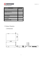
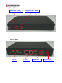
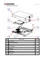
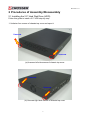
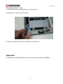
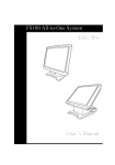
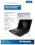
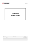
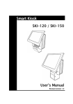
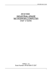
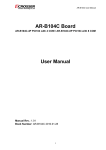
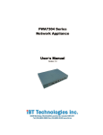
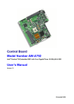
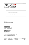
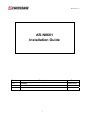
Revision: 1.0
AR-N8601
Installation Guide
Revision
1.0
Description
Release
Date
2009/09/21
1
Revision: 1.0
Contents
1 Introduction to AR-N8601...............................................................................................3
1.1 Specifications ..........................................................................................................3
1.2 Packing List ............................................................................................................4
1.3 System Dissection ..................................................................................................4
2 Procedures of Assembly/Disassembly .........................................................................7
2.1 Installing the 2.5” Hard Disk Drive (HDD) ...............................................................7
2.2 Installing the CF card............................................................................................10
Appendix ..........................................................................................................................10
2
Revision: 1.0
1 Introduction to AR-N8601
Acrosser's Microbox Networking device AR-N8601 is a small, cost-effective and entry-level
UTM (Unified Threat Management) hard ware, which is suitable for small office. Base on
VIA CN700 with ULV Eden 500MHz CPU, the AR-N8601 general very low heat. We also
put a quiet Fan to keep the low noise which will not cause uncomfortable voice. By three
10/100 Lans, the AR-N8601 is sufficient for the small business security hardware solution.
Key features:
1. VIA EDEN ULV 500 CPU.
2. VIA CN700+8237R plus Chipsets.
3. DDRII memory support (533MHz).
4. 3 x 10/100LAN RTL8100C.
5. CF socket, SATA x 1, SATA power, USB x 2.
6. Console, VGA (pinhead), KB/MS (Pinhead).
7. Support PXE boot from LAN.
8. Compact size.
1.1 Specifications
Item
Description
System
AR-N8601
CPU Board
AR-B8601
System
Dimensions
210*150*33(mm)
3
Revision: 1.0
1.2 Packing List
Description
Quantity
AR-N8601
1
Console cable
1
Software driver CD
1
Quick user’s manual
1
Screw pack
1
Power adaptor
1
Power cord
1
SATA cable
1
SATA power cable
1
1.3 System Dissection
(1) Dimensions
4
Revision: 1.0
(2) Front Panel
Led (Power & HDD)
LAN led (Link & ACT)
Back Panel
USB*2
LAN1~3
COM PORT
5
POWER JACK
Revision: 1.0
(3) System Configuration
1
3
2
5
4
6
8
7
Item
Description
Quantity
1
TOP COVER
1
2
HARD DISK BRACKET
1
3
FAN
1
4
BOTTOM BASE
1
5
ANTENNA
1
6
CF SOCKET
1
7
RAM SOCKET
1
8
FOOT PAD
4
6
Revision: 1.0
2 Procedures of Assembly/Disassembly
2.1 Installing the 2.5” Hard Disk Drive (HDD)
Follow this guide to install a 2.5” HDD step-by-step.
1. Unfasten four screws of chassis top cover and open it.
Unscrew
Unscrew
(a) Unscrew left side screws of chassis top cover
Unscrew
Unscrew
(b) Unscrew right side screws of chassis top cover
7
Revision: 1.0
(c) Open chassis top cover
2. Put the 2.5” HDD on the hard disk bracket and using four screws fasten it.
8
Revision: 1.0
3. Connect SATA & power cables of HDD to the correct positions.
4. Note that you can use the cable tie to fasten these cables. To avoid these cables is too
confused.
5.
Finally, assemble the top cover and fasten it with screws.
9
Revision: 1.0
2.2 Installing the CF card.
1. Unfasten four screws of chassis top cover and open it.
2. Insert the CF card into the CF socket.
3. Finally, assemble the top cover and fasten it with screws.
Appendix
You should take apart the HDD bracket first if you want to replace the SDRAM.
10