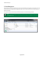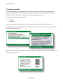
1
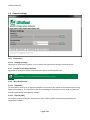
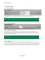
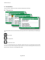
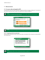
EngineEye – User manual User manual Revision date 2012-08-02 Littelfuse Selco A/S 1 Introduction ......................................................................................................................................................3 2 System Overview ..............................................................................................................................................3 2.1 Basic ..........................................................................................................................................................4 2.2 Advanced ..................................................................................................................................................4 2.3 Professional ..............................................................................................................................................4 3 Getting started - EngineEye Configuration and Engine settings ......................................................................5 4 Getting started .................................................................................................................................................6 5 Inserting the USB cable.....................................................................................................................................6 6 Configuring the EngineEye ...............................................................................................................................6 6.1 Launching the configuration application ..................................................................................................7 6.2 Navigating and editing ..............................................................................................................................8 6.3 Saving and committing the changes to the Handheld Unit ......................................................................8 6.4 General settings ........................................................................................................................................9 6.4.1 Preferences .......................................................................................................................................9 6.4.2 Prompt for working condition ..........................................................................................................9 6.4.3 Ship identification .............................................................................................................................9 6.5 Engine settings....................................................................................................................................... 10 6.5.1 Engine description ......................................................................................................................... 10 6.5.2 Measurement options ................................................................................................................... 10 6.5.3 Working conditions (ISO correction data) ..................................................................................... 11 6.5.4 Operator notifications ................................................................................................................... 11 6.5.5 Mechanical engine parameters ..................................................................................................... 12 7 Using EngineEye – User interface and Functionality ..................................................................................... 13 8 User interface ................................................................................................................................................ 14 8.1 9 The sensor bar ....................................................................................................................................... 14 Measurements............................................................................................................................................... 15 9.1 Pressure and crank angle for MIP.......................................................................................................... 15 9.1.1 Prompting for ISO correction data ................................................................................................ 15 9.2 Cylinder balancing ................................................................................................................................. 18 9.3 Misfiring analysis ................................................................................................................................... 19 Page 1 of 27 Littelfuse Selco A/S 10 Setup .......................................................................................................................................................... 20 10.1 View measurements .............................................................................................................................. 20 10.2 Engine configuration.............................................................................................................................. 21 10.3 System configuration ............................................................................................................................. 22 10.4 Sensor check and status ........................................................................................................................ 23 10.5 Check pressure sensor ........................................................................................................................... 23 10.5.1 Check Crank Angle Sensor (CAS) .................................................................................................... 24 10.5.2 Check TDC sensor .......................................................................................................................... 24 11 Charging ..................................................................................................................................................... 25 12 Data Management ..................................................................................................................................... 26 13 Firmware update ....................................................................................................................................... 27 Page 2 of 27 Littelfuse Selco A/S 1 Introduction 2 System Overview Figure 1 The Overview is an example of an EngineEye installation The EngineEye system consists of multiple parts depending on the ordered version. Page 3 of 27 Littelfuse Selco A/S 2.1 Basic The Basic version includes an EngineEye handheld unit with 1 sensor input and a pressure sensor. The basic version performpressure measurements as a function of time. The Basic version will not support the connection of the TDC or Crank Angle Sensor. 2.2 Advanced The Advanced version includes an EngineEye handheld unit with 2 sensor inputs, a pressure sensor and an inductive TDC sensor. The Advanced version can measure pressure as a function of time and it can provide accurate determination of the TDC point relative to the pressure over time curve. 2.3 Professional The Professional version includes an EngineEye handheld unit with 5 sensor inputs, pressure sensor and a Crank Angle Sensor. The Professional version perform pressure measurements as a function of time (with or without TDC measurement) or pressure measurements as a function of crank angle (with less than 1 degree accuracy). The TDC sensors and the crank angle sensors are provided with a junction box for easy and installation. Optional break-out boxes can be installed alongside the engine. The cable for the break-out boxes can be acquired from Littelfuse Selco. Page 4 of 27 Littelfuse Selco A/S 3 Getting started - EngineEye Configuration and Engine settings Page 5 of 27 Littelfuse Selco A/S 4 Getting started Before using the EngineEye an engine configuration must be created. The configuration must reflect the engine being tested Note: All parameters (except the number of cylinders) – can be edited and corrected when the measurement is loaded into the PC Software. 5 Inserting the USB cable When the USB cable is inserted, the handheld unit locks itself and enters a “remote administration” mode. Note: If the EngineEye is measuring (MIP, Balancing, misfiring) or viewing measurement and the “USB cable is inserted” EngineEye will intentionally disregard the USB cable and continue with its current task. When the USB cable is inserted, the battery charging circuit is also activated. That happened regardless of the state of the user interface. This can be seen from the battery icon changing to the “charging” icon. When connecting the EngineEye to a computer, a EngineEye configuration and a EngineEye data drive will appear. Select the configuration drive and double-click the “config” file to open the configuration tool. 6 Configuring the EngineEye The EngineEye allows configuration either directly through the user interface of the handheld or by using a computer and the onboard configuration application. The examples in this section use the configuration application. Page 6 of 27 Littelfuse Selco A/S 6.1 Launching the configuration application When connecting the EngineEye to a computer via a USB cable EngineEye drives are easily recognized by the EngineEye logo. Figure 2 The EngineEye drives in the file manager The drive named “EngineEye Configuration” contains the EngineEye configuration application. Double-clicking the “config” file launches the configuration application. Figure 3 The startup screen of the EngineEye configuration application Note: The configuration application only runs on a MS Windows XP or greater. Page 7 of 27 Littelfuse Selco A/S 6.2 Navigating and editing The configuration application presents the settings in an intuitive manner by dividing the settings into different tabs. The general settings and engine specific settings are presented in individual tabs. (The number of available engine configurations differs within the variants). The settings can be reset to their default values or reverted to the values they initially had when the configuration application first launched. The settings are easily altered and their possible values are presented either in drop down boxes (Limited set of possible values) or by listing the valid range (And guard against invalid inputs). Figure 4 Editing parameters in the configuration application The Configuration application also shows comments where necessary to understand consequences of certain settings. In the example above, setting Resolution to high brings up a note instructing the operator that the measuring cycle will take much longer when high resolution is selected. 6.3 Saving and committing the changes to the Handheld Unit Changes to the configuration application using the programming software can be saved using the “save all” or “Save and close” button. The programming software tracks all changes made to the configuration even when moving from tab to tab without saving. When the USB cable is disconnected the EngineEye will detect the saved configuration and prompt the operator to either load the configuration in or discard it. Figure 5 EngineEye detects a saved configuration and loads it Page 8 of 27 Littelfuse Selco A/S 6.4 General settings 6.4.1 Preferences 6.4.1.1 Display warnings EngineEye can show warnings about e.g. hot surfaces and high pressure during the measuring cycle. 6.4.2 Prompt for working condition EngineEye can prompt for ISO correction data at the start of a measurement cycle. Note: Safety Warnings can also be disabled during the measuring procedure 6.4.3 Ship identification 6.4.3.1 Ship name The ship name is common for all engines onboard the vessel and is also used in the PC software when storing engine measurements.. The ship name is also used as heading for measurements and is used on graphs and printouts generated by the EngineEye software. 6.4.3.2 Ship ID (IMO) The ship ID is used as heading for measurements and is used on graphs and printouts generated by the EngineEye PC software. Page 9 of 27 Littelfuse Selco A/S 6.5 Engine settings 6.5.1 Engine description These settings are only used for reference on the user interface screen and on print-outs Note: Name is the only setting that must be to be unique. Ensure that the name is entered correctly as all stored data is saved under the entered name as changes cannot be applied later. The name is also case sensitive 6.5.2 Measurement options 6.5.2.1 Number of work strokes The number of work strokes defines how many cycles the EngineEye will record during each pressure measurement. Each work stroke equals a 360/720 degree turn of the crank shaft. Any number of strokes between 1 and 30 can be specified. Note: 360/720 depends on engine type. 360 is used for two-stroke engines and 720 is used for four-stroke engines 6.5.2.2 Resolution Resolution determines the number of measurements carried out during each work stroke. This parameter should be kept as standard unless extra resolution is specifically required. High resolution measurements take significantly longer than standard resolution measurements, as more data has to be acquired and stored. Page 10 of 27 Littelfuse Selco A/S 6.5.3 Working conditions (ISO correction data) ISO correction enables the operator to compare engine performance and engine conditions regardless of where measurements were carried out. Working conditions is also prompted during measurements 6.5.4 Operator notifications If set to CAS/TDC, EngineEye will prompt, using a warning screen, for a CAS/TDC sensor before doing measurements. If set to None, but a CAS/TDC sensor is present during measuring of cylinder 1, the EngineEye requires that the sensor is present for the remaining cylinders. Page 11 of 27 Littelfuse Selco A/S 6.5.5 Mechanical engine parameters Mechanical engine parameters contain generic settings for all engine types. The most important settings are two or four stroke definitions and the cylinder dimensions to calculate piston travel as well as cylinder volume. 6.5.5.1 Generic engine settings The engine type, engine layout and cylinder dimension must be programmed regardless of EngineEye model (Basic, Advanced or Professional). 6.5.5.2 Numbers of cylinders This parameter determines the number of consecutive readings performed during the measurement cycle. 6.5.5.3 Cylinder firing angle There are as many cylinder firing angles parameters as there are cylinders. The firing angle for each cylinder is used to calculate the crank shafts angular displacement versus a cylinders TDC position. The firing angle can be found in the specification of the engine (cylinder 1 is typically 0 °). The angle can be set to any value between 0 and 360 degrees. Note: For the basic model the cylinder firing angle can be disregarded. These settings only apply to applications that use the Crank Angle Sensor or TDC sensor. Note: During installation of CAS belt, the joining of the belt ends must be at TDC for Cylinder 1. Page 12 of 27 Littelfuse Selco A/S 7 Using EngineEye – User interface and Functionality Page 13 of 27 Littelfuse Selco A/S 8 User interface The user interface is divided into a Sensor status bar, Measurements and Setup. 8.1 The sensor bar The left hand side of the user interface shows sensor type; each sensor is represented by an icon depicting its type. Pressure sensor Crank angle sensor Top Dead Center sensor If a sensor is connected the sensor icon is displayed in yellow if the sensor is not measuring any activity. When the sensor is active this will be displayed as a green colored icon. Sensors to be displayed in the sensor bar are; pressure sensor, TDC sensor or Crank Angle Sensor (CAS). Page 14 of 27 Littelfuse Selco A/S 9 Measurements 9.1 Pressure and crank angle for MIP A measurement cycle will include the number of cylinders specified in the engine configuration. The number of work strokes measured on each cylinder is also specified in the engine configuration. Note: The pressure and crank angle measurements always start at cylinder number one and the measuring procedure is explained on the EngineEye display Note: The Safety warning can be disabled, either by removing the check mark or through the User interface 9.1.1 Prompting for ISO correction data Before doing the measurements ISO correction data needs to be adjusted. These settings are prompted before each measurement. Note: The prompting for ISO correction can be disabled through the configuration Page 15 of 27 Littelfuse Selco A/S The measuring sequence follows an easily identified path: Move, Clean, Mount, Measure, Validate and Unmount. After the measuring cycle is completed the data will be stored in the EngineEye’s internal memory. Page 16 of 27 Littelfuse Selco A/S After saving measurements a graphic presentation of the measured cylinder will be displayed. If any concerns are raised about the result after the measurement cycle is completed, it is possible to redo the measurements by pressing arrow key left. Repeat the process on all cylinders to complete the measurements. The measurements can then be exported to the PC software for storage and further use. Page 17 of 27 Littelfuse Selco A/S 9.2 Cylinder balancing Cylinder balancing gives an indication of how the engine is performing. If the measured pressure in a cylinder is below the average measured set point this could indicate a malfunctioning engine part in the cylinder assembly. After completing a cylinder balancing measurement the operator is presented with a cylinder parade. The cylinder parade will show any difference in measured average pressure. Note: Cylinder balancing should be performed with a constant engine load (MCR) Press → or ← for parade view Press ↑↓to change cylinder Press for reset Page 18 of 27 Littelfuse Selco A/S 9.3 Misfiring analysis A misfiring cylinder in an engine results in decreased engine performance and increased exhaust emissions. Misfiring can if not diagnosed in time lead to engine failure. Misfiring analysis is a long term diagnostic process which means the EngineEye must measure continuously on the cylinder for an extended periode of time. The result is a chart showing changes in pressure per work stroke where each stroke is summarized into bar graphs. Adjustments to the measuring band and margin can be done using the arrow keys. Long pressing the arrow keys makes the measuring bandwidth “jump” forward at a higher speed. Any measurement outside the bandwidth is considered a misfire and therefore it is very important that the bandwidth is adjusted correctly. Note: Any adjustment to the measuring bandwidth is saved in the selected engine configuration. Therefore no adjustment is needed for the following misfiring analysis measurements. Measurements are started and stopped using the “play” button on the EngineEye Note: Misfiring analysis should be performed with a constant engine load (MCR) Page 19 of 27 Littelfuse Selco A/S 10 Setup 10.1 View measurements View measurements allow the operator to access old measurements. The measurements are saved under configuration type, year, month and measured time. Each stored measurement will enable the operator to review the measurements Page 20 of 27 Littelfuse Selco A/S 10.2 Engine configuration The EngineEye supports more than one engine and each engine can be configured with a name and a number of parameters describing the properties and current state of the engine. The options in the user interface are the same as in the PC programming tool. Note: Some parameters should be adjusted prior to doing a measurement cycle. The parameters are mention under ISO correction section. Page 21 of 27 Littelfuse Selco A/S 10.3 System configuration The System Configuration includes configuration parameters that are related to the function and use of the EngineEye unit. Systems settings can be used to change date, time, see variant information and reset the configuration. The options in the user interface are the same as in the PC programming tool. Page 22 of 27 Littelfuse Selco A/S 10.4 Sensor check and status Sensor check and status are used to confirm that the installed sensor is working correctly and it gives an overview of measured values on the connected sensors. It is also a valuable tool for testing the installation both during maintenance and commissioning as it indicates if signals are received from a sensor. The Operator can connect the handheld unit to any Junction Box (which can be placed physically close to the sensor), allowing for “local” monitoring of the signal whilst installing and testing the sensor. 10.5 Check pressure sensor The check pressure sensor function is used with a constant pressure source. However, the sensor can only withstand a max. pressure of 250bar. Exceeding this limit may cause the pressure sensor to malfunction. If the operator wants to check the sensor with a variable pressure source it is recommended using the cylinder balancing function. Page 23 of 27 Littelfuse Selco A/S 10.5.1 Check Crank Angle Sensor (CAS) The crank Angle Sensor check provides the operator with a commission tool that indicates the engine rpm, tooth detection and signal quality. Engine RPM is used as a day to day sensor check tool which will show if the sensor is working or not. The tooth detection only works at very low speeds, example. If the engine is being turned using the turning gear the tooth detection will be useable. Therefore the tooth detection is useful during installation and commissioning to show if the sensor is installed correctly. 10.5.2 Check TDC sensor The tooth detection only works at very low speeds, when the engine is running at normal speeds the tooth detection will be displayed as green. Therefore the TDC tooth detection is useful during installation and commissioning to show if the sensor is installed correctly. Note: A led in the TDC sensor junction box can also be used to verify the signal Page 24 of 27 Littelfuse Selco A/S 11 Charging When connecting the battery charger the EngineEye will automatically turn on. The EngineEye will display if the unit is being charged or running on battery power. The icon is displayed in the top right corner of the unit. Keep the EngineEye fully charged to improve the battery lifetime, either by charging to full battery capacity after each use before storing the unit or keep the EngineEye connected to the battery charger when not in use. Note: To reduce charging time switch the EngineEye off (The power LED will be slow flashing) If the battery power is low the EngineEye will show a warning screen before the unit is switched off. It the EngineEye shuts down due to no battery power the date and time is still maintained by an internal battery dedicated to this function. Configuration and other date stored on the EngineEye will also remain intact as this is stored in the internal memory. Note: When the EngineEye is connected to a PC via the USB cable the charging icon will be showing the charging icon. However, some USB ports does not supply the needed voltage and therefore it will not charge the battery ) Page 25 of 27 Littelfuse Selco A/S 12 Data Management Measurements are stored on the Data drive and can be accessed when the EngineEye is connected to a PC. The measurement files are organized by configuration number / year / month and time if more measurements are taken the same day. The internal memory card can hold up to 100 measurements at normal measuring resolution. Note: Deleting measurements will have to be done using windows file manager. The EngineEye will not prompt for a full memory card. Page 26 of 27 Littelfuse Selco A/S 13 Firmware update The firmware upgrade runs automatically once initiated. It is not necessary to export the configuration or measurement files before the firmware upgrade. The EngineEye will automatically backup the configuration and will restore the configuration automatically as part of the upgrade procedure. The EngineEye firmware consists of two files: E5000.bin E5000.md5 In order to upgrade the firmware, these two files must be copied to the EngineEye Configuration drive. The EngineEye has a firmware upgrade instruction that provides the operator with a step by step procedure of how to firmware update the unit. When the firmware has been upgraded the operator will get the following verification screen indicating that all steps have been completed. Page 27 of 27