1
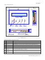
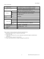
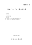
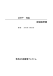
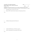
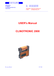
EFP−RC
Users Manual
Third edition January 2005
Suisei electronics system Co., Ltd.
First edition
June, 2004
Second edition
September, 2004
Third edition
January, 2005
Copyrightc 2004-2005
Suisei electronics system Co., Ltd
EFP-RC is ROM programmer who can use it only for the single-chip microcomputer made of the Renesas
technology.
It is not possible to use for writing in other MCU, and to use it for other usages.
The guaranteed term of EFP-RC has been one year since purchase.
Meanwhile, the defect that occurs due to the problem in manufacturing is repaired free of charge.
Please contact the shop or our company.
However, in the following case, it becomes for a fee.
Breakage of articles of consumption (a socket, switch, etc.)
When it is made to damage by the mistake of handling of EFP-RC.
Moreover, it is not warrantable of the cost generated by the defect and those of MCU programmed
with this device.
EFP-RC is a product for the development usage.
Please confirm the following by customer's responsibility before using EFP-RC for the mass production usage.
Please check to see the factor which makes use environment and an used procedure generate fault in MCU
writing does not lurk.
The contents indicated by this EFP-RC manual may be changed without a preliminary announcement by the
reasons of performance improvement etc. in the future from now on.
In addition, please understand that our company cannot take the responsibility about the result which written
contents employed.
Please give me the inquiry about the contents of this description and software to the following.
In addition, on the occasion of the inquiry, it is receiving by E-mail and FAX.
To
5-24, Tsurumi 6chome, Tsurumi-ku, Osaka Japan
Suisei Electronics System Co., Ltd.
FAX (06)6913-4534
E-mail : [email protected]
HP
: http://www.suisei.co.jp/
post_code 538-0053
Users Manual
Manual contents
Page
2
1. EFP-RC externals chart.
Externals chart
Externals explanation
2. EFP-RC Method of connecting
3. Notes in handling
About the power supply input.
About the target connection..
About the operating switch.
4
4. About the operation method.
4
5. Connector table.
5
6. Basic specification.
6
7. Detaching of Compact-Flash card.
6
8. Product composition.
7
Inquiries
7
1
Suisei Electronics System Co., Ltd.
Users Manual
1. EFP-RC externals chart.
Fig.1
Externals chart
Explanation of outline of externals each part.
Name
①
②
③
④
⑤
⑥
⑦
⑧
⑨
Outline
Cursor key
Cursor movement key to select content displayed in LCD.
A key
Use changes on each occasion.
B key
The backing key: It is a key that returns an operation route that is advanced up to now.
Set Key
It is a key that executes the command, and decides the parameter.
LCD Display
The command and the parameter, etc. are displayed.
Compact-Flash card
The writing data, the script file, and the upgrade firmware are memorized there.
Target-connection
Connects with the target substrate when the serial-write.
connector
External power supply
(Refer to the operating manual. )
The same specification for EFP-1 as serial unit.
Power supply connector. 1.3φ round pin Jack.
(Outside=GND Inside=Vcc)
connector
USB_I/F connector
It uses it the data to download and to control from the personal computer.
2
Suisei Electronics System Co., Ltd.
Users Manual
2. EFP-RC Method of connecting
Environment of operation
Windows98SE/Me/2000/XP
Personal computer
User target system
5V Supplies from outside
Control software only for EFP-RC
(note 1)
Power cable (note 1)
USB cable (note 1)
EFP-RC
Target connection cable (note 1)
note 1 : It is attached to EFP-RC
Fig.2 Example of connecting EFP-RC
2.1. Connection at the case of Data-file transfer.
① TG cable:
Especially, it is unnecessary of the connection.
② The USB cable: It is necessary to connect it.
(The power is supplied by the USB cable. )
③ The power cable: Especially, it is unnecessary of the connection.
2.2. Connection at the case of writing to MCU.
① TG cable: Connected necessity. (The power supply to EFP-RC is done ) Note2
② USB cable: Necessity none connection.
③ Power cable: Connection if necessary. (Note 3:, the following reference )
Note 2: The TG cable might be different from above-mentioned figure at the shipment time.
Note 3: In the following cases, please supply power by the power supply connector. (4V-5.5V)
( It is supplied by the target connector usually.)
a. When the voltage of the target is less than 3.3V.
( When the voltage becomes 3.0V or less, operation becomes unstable )
b. When repeatedly operation is executed.
( The power supply is turned off once, and it will turn on again. )
3
Suisei Electronics System Co., Ltd.
Users Manual
3. Notes on Handling
3.1. Power Supply Input
1: The power supply of EFP-RC can be inputted from the following lines.
⑧ External power supply connector (CN1 Outside=GND Inside=Vcc /4.5V-5V)
⑨ USB_I/F connector (CN3_1: +5V, CN3_5: GND)
⑦ Target connector(
CN5_1: GND,CN5_4: T_VDD)
* When two kinds of power supplies are connected simultaneously, it is supplied from a higher
voltage side.
2: Please use external power supply voltage more than 4V and is less than 5.5V .
Moreover, when the voltage of a target is less than [ 3.3V ], please use an external power supply.
3: Connecting EFP-RC of a power supply OFF and the target-board of a power supply ON should avoid.
4: When you repeat writing and you perform it, please use an external power supply.
・
In order to shorten the loss of starting time generated with power supplies ON and OFF.
・
In order to lessen the burden of the power supply by the side of a target.
EFP-RC Power supply current (Standard)
Supply voltage
Supply current
3.3V
0.3A
4.0V
0.25A
5.0V
0.15A
3.2. About the target connection method.
When you connect with a target board, please refer to the following data.
EF1SRP-01U Users guide.
EF1SRP-01US2 Users guide.
Each supplementary data of MCU
3.3. About Switch
* When you operate a switch, please do not press down by strong power.
4. About Operation Method
Please understand the following content before executing writing ROM by using EFP-RC.
① Files used with EFP-RC are the following two files.
Writing data file (xxx.HXW): File of form looks like binary that converts HEX file.
Script file (xxx.PBT) for writing: Text form file that set writing procedure.
・Please forward it to EFP-RC after executing the control software with the personal computer, and
making HXW file.
・Please forward it to EFP-RC with the control software after making the script file with a text editor.
・There is a method of transmitting data to EFP-RC with the control software through USB_I/F.
・Moreover, a Compact-Flash card (CF) is removed from an EFP-RC main body, and there is the
method of writing in direct CF by Compact-Flash R/W.
( Please refer to a [EFP-RC control software manual] about the data transfer method )
( Please refer to a [EFP-RC operations manual] about a control software script file )
② When you write in the file set up by '①' by EFP-RC, please write in by choosing a LCD display menu.
( Please refer to a [EFP-RC operation manual] about operation of EFP-RC )
4
Suisei Electronics System Co., Ltd.
Users Manual
5. Connector Table
5.1. Power Supply Input Pin Jack (CN1)
Signal name
In/Out
Outside 0V
Inside VIN_Ext
Explanation
In
0V Input
In
4V to 5.5V Input
5.2. USB I/F Connector (CN3)
Signal name
In/Out
In
Explanation
1
V_BUS
USB power supply (+5V): Use it as a power supply of EFP-RC.
2
D-
In-Out
Differential Data line (?Side)
3
D+
In-Out
Differential Data line (+Side)
4
(N.C)
−
5
GND
In
USB GND
5.3. Connector for Internal MCU Rewriting (CN4)
Signal name
In/Out
Explanation
1
GND
GND
2
RXD
Out
MCU to (EFP) Reply serial data
3
BUSY
Out
MCU Busy Signal
4
VPP
(N.C)
5
VDD
Out
6
SCLK
In
The clock signal for synchronous communications
7
TXD
In
(EFP)to MCU Receiving serial data
8
PGM/OE
In
Write-in read-out pulse
9
Reset
In
Reset signal input
10
GND
Power supply output (for EFP buffer IC)
GND
5.4. Target Connector (CN5)
Signal name
In/Out
Explanation
1
GND
GND
2
(N.C)
−
3
T_VPP
Out
Target Programming power supply output
4
T_VDD
Out
Target power supply input (3.3V to 5V)
5
T_VPP2
Out
Target Programming power supply output 2
6
Err
Out
External display signal: Programming execution error
7
Busy
Out
External display signal: Under command execution
8
T_PGM/OE
Out
Target : write-in read-out pulse
9
T_SCLK
Out
Target : Clock for synchronous communications
10
T_TXD
Out
11
T_RXD
In
Target : Serial receiving data
12
T_Busy
In
Target : Busy signal
13
Start
In
External switch : Start
14
T_Reset
Out
15
(N.C)
−
16
GND
Target : Serial transmitting data
Target reset control signal
GND
5
Suisei Electronics System Co., Ltd.
Users Manual
6. Basic Specification
Program system
A system MCU write-in [ made from RENESAS technology ]
Flash ROM built-in MCU made from RENESAS technology
MCU for a program
M16C/6x, and / 8x M16C/6xP R8 C Qz_ROM
Memory
Communication
interface
CF
32MB or more, a user program, for write-in script storing
ROM
For 256KB flash ROM (MCU built-in) firmware program
RAM
20KB (MCU built-in)
USB 1.1
12Mbps(Max)
Correspondence OS
Power supply
etc
Windows98SE,Me,2000,XP
USB I/F
From USB bus power to supply (5V)
User target
From a user target system to supply (3.3V to 5V)
exclusive
terminal
From an exclusive power supply jack to supply (5V)
Power consumption
3.3V-400mA
5V-250mA (Max)
Outside size
108(W) x78(D) x23 (H)
Weight
150g
[mm]
7. Data Transfer Procedure by Removal and R/W of CompactFlash Card
1: The lid on the case back side is removed. (It slides outside)
2: Draw out CF card.
3: Insert in CF_R/W by which CF card was connected to the personal computer, and perform data
transfer etc.
4: After data transfer removes CF card from R/W.
5: Please cover with the lid of CF card after inserting CF card in EFP-RC.
6
Suisei Electronics System Co., Ltd.
Users Manual
8. Product Composition (Packing Article)
Product composition of the set corresponding to QzROM
Name
Explanation
1: EFP-RC main part
It Compact-Flash builds in an EFP-RC main part.
2: USB cable
1.5m length
3: Power supply cable
1m length
MinUSB Cable
(a supply side tip is unsettled)
4: EFXQZP-01 conversion board
5:EFTGCB-16W16W
6:EFTGCB-16WX
7:EF0PCB-10WX
300mm length of EFP-RC EFXQZP-01 connecting cables
(both-sides 16PinCN processing)
300mm length of target connecting cables
(single-sided 16PinCN processing)
Operation part connection connector 1000mm length (single-sided
10PinCN processing)
8: Control software
Inside of CD
7: Manuals
Inside of CD (User, Operation, Control software Manuals )
8:Users Manual
This document
EFXQZP-01 description
Inquiry
5-24, Tsurumi 6chome, Tsurumi-ku, Osaka Japan
post_code 538-0053
Suisei Electronics System Co., Ltd.
FAX (06)6913-4534
E-mail : [email protected]
H.P
: http://www.suisei.co.jp/
7
Suisei Electronics System Co., Ltd.