1
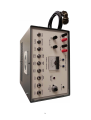
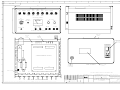
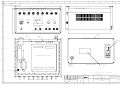
INSTRUCTION MANUAL
FOR OPERATION AND
MAINTENANCE OF
ACTUATOR
CHARGER / TESTER
Pub. No. 3373 – Issue 5
© Regulateurs Europa Ltd 2011
The contents of this document are the exclusive property
of Regulateurs Europa Ltd
They must not be copied or reproduced without the written
authorisation of the Company
2
3
INDEX
1
REVISION HISTORY............................................................................................... 5
2
FOREWORD............................................................................................................ 6
3
GENERAL SAFETY ................................................................................................ 7
4
5
3.1
General ........................................................................................................ 7
3.2
Safety Of Personnel ................................................................................... 7
GENERAL ELECTROSTATIC PRECAUTIONS ..................................................... 8
4.1
Electrostatic Devices ................................................................................. 8
4.2
Electrical Interference................................................................................ 8
DESCRIPTION ........................................................................................................ 9
5.1
6
Specification ............................................................................................... 9
PROCEDURES FOR SETTING COIL MAGNET TO CORRECT SENSITIVITY... 10
6.1
Equipment Setup...................................................................................... 10
6.2
Charging the Magnet................................................................................ 10
6.3
Discharging the Magnet........................................................................... 11
6.4
Checking Magnet Sensitivity................................................................... 11
6.5
Reverse Acting Actuator Settings Difference........................................ 11
6.6
Checking for Full Range Capability........................................................ 11
7
MANUAL SWEEP ................................................................................................. 12
8
STEP RESPONSE................................................................................................. 12
9
AUTO RAMP ......................................................................................................... 12
10
RECORDER DRIVE .............................................................................................. 13
11
DRAWINGS ........................................................................................................... 14
12
SERVICE FACILITIES........................................................................................... 17
4
1
REVISION HISTORY
Issue
1
2
3
4
5
Date
05.03.96
07.01.97
07.06.00
10.01.03
03.02.11
Name
G Nunn
M. Birkin
5
Signature
2
FOREWORD
These instructions have been compiled to assist personnel responsible for the
operation and maintenance of equipment manufactured by Regulateurs Europa
Ltd.
Care has been taken to ensure that the equipment has been accurately
represented, but it should be appreciated that, with the continued progress of
design and the diversity of application, certain items may differ in detail.
It should be noted that these instructions are issued for general information and do
not constitute a specification of the equipment.
Whilst reserving the right to make any alteration in design which they may
consider advisable the manufacturers absolve themselves from making any such
alteration retrospective.
In addition to the information given herein, practical advice and assistance are
always available from our Customer Support Department.
6
3
GENERAL SAFETY
Before carrying out any repairs, adjustments or maintenance to any equipment by
Regulateurs Europa Ltd, it is essential the following safety precautions be observed:
3.1
General
The equipment may contain one or more of the following:
i)
ii)
iii)
iv)
v)
vi)
vii)
High voltages
Rotating parts
High pressure oil
Compressed air
Preloaded springs
PCB’s
Microprocessors
All of the above items represent a potential danger or hazard to operating personnel
and the operator should take care to make himself thoroughly familiar with the
operating principles, methods of adjustment and the dismantling and assembly
procedures (where applicable) concerning the equipment in his care.
3.2
Safety Of Personnel
Before carrying out any repairs, adjustments or maintenance to the equipment or
unit, the operator should ensure that any such unit or equipment cannot be activated
from a remote position. To achieve this condition, he should ensure that all
electrical/pneumatic supplies to the prime mover starter system are isolated at their
incoming source and that all electrical supplies to control systems are isolated by the
withdrawal of the relevant fuses or by disconnecting the incoming electrical supply at
the control board. In addition to these precautions, visual-warning notices should be
prominently displayed by the equipment or unit and also at any remote control
positions. Where control cabinets and consoles are secured with keys, all such keys
should be in the possession of the operator carrying out the work. Information
regarding position, level and type of work to be carried out should also be made
available to the ‘Engineer in Charge’ of the installation to prevent attempted use of
the equipment or unit during breakdown.
In the case of electrical/electronic control systems, the operator should make careful
reference to the Instruction manual to ensure that he is aware of any special safety
precautions which are peculiar to that particular equipment or unit.
Before the equipment or unit is finally released for operation, operating personnel
should ensure that all tools and repair equipment has been removed and that all
safety guards are securely replaced (where applicable). All fuses should be
replaced and operating mediums (electrical and pneumatic supplies) should be
opened or reconnected.
7
4
GENERAL ELECTROSTATIC PRECAUTIONS
4.1
Electrostatic Devices
WARNING!
This equipment contains components that are electrostatic sensitive. Electrostatic
damage can cause immediate failure or shortening of useful life.
Servicing PCBs at component level should be done at an electrostatic free
workstation. If site work cannot be avoided, the following precautions must be taken:
4.2
a)
All tool tips must be earthed.
b)
Personal wrist or ankle earth straps must be worn. To protect against
personal hazard, the resistance of the earth strap should be approximately
250k ohms.
c)
PCBs or components should be transported in static free packaging and
when removed from packaging laid on static free surface after or prior to
assembly.
Electrical Interference
To avoid possible malfunction of the equipment or infringement of Electrical
Interference Regulations, the following precautions must be taken:
a)
All cable screens to be terminated and earthed at the entry to the equipment
b)
The equipment to have a low impedance earth
c)
All doors and covers etc to be firmly secured.
8
5
DESCRIPTION
The charger provides means of charging the magnet in the 2200 series actuators
by capacitor discharge technique. The correct sensitivity is checked by observing
the actuator output movement against a measured change in actuator drive
current. A ramp generator is provided to control the actuator current to sweep the
actuator output for checking hysteresis. An actuator position transducer is
required to drive one axis of an X-Y plotter, a voltage signal is provided from the
charger to drive the other axis.
5.1
Specification
Power Supply:
Nom. 110V or 230V
50/60Hz 40 VA
Charge Potential:
280 volts nominal
Discharge:
As charge but with 100 to 1100 ohms
variable limit resistor
Test current:
0 to 1 Amp DC
Ramp time:
Fast, 10 s/cycle
Slow, 200 s/cycle
X-axis drive:
0 to 1 Volt floating 1 ohm source
9
6
PROCEDURES FOR SETTING COIL MAGNET TO CORRECT SENSITIVITY
WARNING!
This section will deal with the calibration of a ‘NORMAL’ acting actuator and
assumes that the following has been completed first:
•
In the case of a ‘ballhead backup’ governor/actuator that all mechanical
settings have been made.
•
The ‘Link’ between pins A and B has been removed (plug or terminal
block).
•
Any diode fitted has been removed from the Actuator coil wiring.
During this setup procedure the magnet will be fully charged (magnetised) and
then discharged in steps. At each stage the sensitivity will be checked for
conformity.
6.1
Equipment Setup
a) Fit actuator to a test rig that enables the drive shaft to be driven.
b) Set up pilot valve lap as described in the actuator user manual.
c) Connect actuator to the Actuator Charger/Tester box by means of the 4 pin
socket via a suitable terminal to plug adaptor. (Coil wire A=BROWN ~
B=ORANGE ~ C=RED)
d) Connect a digital DC ammeter to the red and black ‘METER’ terminals on the
front of the Actuator Charger/Tester box.
e) Turn on mains power via the switch at the rear of the Actuator Charger/Tester
box.
6.2
Charging the Magnet
a) Set ‘NORMAL/REV’ switch to ‘NORMAL’.
b) Set the ‘CHARGE/DISCHARGE’ switch to the ‘CHARGE’ position. Check that
the ‘CHARGE AVAILABLE’ lamp is illuminated.
c) Hold down the ‘TEST/CHARGE’ switch in the ‘CHARGE’ position.
d) Press down the ‘PULSE’ switch and hold for approximately 3 seconds, then
release both switches. During this pulse process the ‘CHARGE AVAILABLE’
lamp will extinguish temporarily.
The magnet now has a full magnetic charge.
10
6.3
Discharging the Magnet
a)
b)
c)
d)
6.4
Set the ‘CHARGE/DISCHARGE’ switch to ‘DISCHARGE’.
Turn the ‘SET DISCHARGE ‘potentiometer to a scale reading of 5.0.
Hold down the ‘TEST/CHARGE’ switch in the ‘CHARGE’ position.
Press down the ‘PULSE’ switch and hold for approximately 3 seconds, then
release both switches.
Checking Magnet Sensitivity
a) Leave the ‘TEST/CHARGE’ switch in the ‘TEST’ position.
b) Set the ‘RAMP/CHARGE-STEP’ switch to ‘STEP’.
c) Set the ‘MAX STEP/MIN STEP’ switch to ‘MIN STEP’ and adjust ‘SET STEP
MIN’ potentiometer to give a 0.250A reading on the digital ammeter.
d) Adjust actuator bias screw to set the output scale to a reading of 2.0 divisions.
e) Set ‘MAX STEP/MIN STEP’ switch to ‘MAX STEP’ and adjust ‘SET STEP
MAX’ potentiometer to give a 0.750A reading on the digital ammeter.
f) Operate ‘MAX STEP/MIN STEP’ switch between ‘MIN’ and ‘MAX’ and observe
the output scale readings. (The output scale should read 2.0 divisions at
0.250A and 8.0 divisions at 0.750A.)
g) If the magnetic charge is too sensitive (range larger than 6.0 divisions) then
turn the ‘SET DISCHARGE’ potentiometer clockwise in small increments and
at each increment repeat steps in section 6.3 followed by those in section 6.4.
h) Should too much charge have been removed then a full recharge is required.
Repeat steps 6.2, 6.3 and 6.4 until correct setting is achieved.
6.5
Reverse Acting Actuator Settings Difference
For reverse acting actuators the ‘NORMAL/REV’ switch is set to the ‘REV’ position
and the settings are output scale 2.0 divisions = 0.750A and output scale 8.0
divisions = 0.250A. The CHARGE and DISCHARGING of the magnet on a
‘reverse acting’ actuator is done in the same way as the ‘normal acting’ actuator
except the different settings need to be observed.
6.6
Checking for Full Range Capability
a) Leave the ‘TEST/CHARGE’ switch in the ‘TEST’ position.
b) Set the ‘RAMP/CHARGE-STEP’ switch to ‘STEP’.
c) Set the ‘MAX STEP/MIN STEP’ switch to ‘MIN’ and adjust ‘SET STEP MIN’
potentiometer to read 0.000A on the digital ammeter. The output scale
position should be 0.0 divisions.
d) Turn the ‘SET STEP MIN’ potentiometer clockwise to read 1.000A on the
digital ammeter. The output scale position should be 10.0 divisions or above.
e) Return ‘SET STEP MIN’ potentiometer to read 0.250A on the digital ammeter.
f) Turn off mains power via the switch at the rear of the Actuator Charger/Tester
box.
11
When all settings are correct the coil leads are to be soldered onto the 4 pin fixed
plug ensuring that pins A and B are linked together. After soldering has been
completed, reconnect the Actuator Charger/Tester box and confirm settings. The
bias screw may need readjusting - this is normal.
Note: If any diode has been removed prior to following the above procedures, then
it needs to be re-installed before returning the actuator to service.
7
MANUAL SWEEP
a)
b)
c)
d)
8
Set the ‘RESET/START’ switch to ‘START’.
Set the ‘RAMP/CHARGE STEP’ switch to ‘STEP’.
Set the ‘MAX STEP/MIN STEP’ switch to ‘MIN STEP’.
Sweep the actuator by manually adjusting the ‘SET STEP MIN’ potentiometer.
STEP RESPONSE
a) Set the ‘RAMP/CHARGE STEP’ switch to ‘STEP’.
b) Set the ‘MAX STEP/MIN STEP’ switch to ‘MIN STEP’ or ‘MAX STEP’.
c) If ‘MIN STEP’ was set then the actuator current will be set by the ‘SET STEP
MIN’ potentiometer. Likewise, if ‘MAX STEP’ was set then the actuator current
will be set by the ‘SET STEP MAX’ potentiometer. Both of the potentiometer
settings are adjustable to permit the configuration of the step amplitude.
9
AUTO RAMP
a) Set the ‘RAMP/CHARGE STEP’ switch to ‘RAMP’.
b) Set the ‘RESET/START’ switch to ‘RESET’.
c) Check the ramp amplitude by setting the ‘MAX RAMP/MIN RAMP’ switch to
‘MIN RAMP’ (in which case the actuator current will be set by the ‘SET RAMP
MIN’ potentiometer below the analogue gauge), or ‘MAX RAMP’ (in which
case the actuator current will be set by the ‘SET RAMP MAX’ potentiometer
below the analogue gauge). Both potentiometers can be adjusted to permit the
configuration of the ramp amplitude.
d) Set the ‘FAST RAMP/SLOW RAMP’ switch to ‘SLOW RAMP’ to enable a slow
ramp (suited to most tests). If a fast ramp is required (e.g. for bedding in) then
‘FAST RAMP’ should be set.
12
10
RECORDER DRIVE
A 0 to 1 volt signal generated from the actuator current passing through a 1 ohm
resistor is available from the red and black ‘X-AXIS’ terminals on the front of the
Actuator Charger/Tester box. This can be used to drive an X-Y recorder for
hysteresis checking.
Set the ‘FAST RAMP / SLOW RAMP’ switch to ‘SLOW RAMP’ for this test.
13
11
DRAWINGS
Layout
110V
230V
AG818
AG825
14
1
DWG.
NO.
2
3
4
5
6
7
8
9
10
AG 818
305
17
280
16
A
TEST
NORMAL
RAMP
MAX
STEP
MAX
RAMP
FAST
RAMP
CHARGE
REV
CHARGE/
STEP
MIN
STEP
MIN
RAMP
SLOW
RAMP
RESET
CHARGE
START DISCHARGE PULSE
B
177
ACTUATOR CURRENT
SET
DISCHARGE
2
30 0
0 90
.4
.6
.8
SET STEP
MIN
MAX
1
7
80 0
10
.2
0
CHARGE
AVAILABLE
5040
60
(LED1)
(VR4)
(VR5)
(VR7)
SET RAMP
MIN
MAX
SUPPLY ON
(LED2)
(VR2)
C
X-AXIS
METER
(VR1)
(T3)
(T4)
(T1)
(T2)
ACTUATOR CHARGER/TESTER
NAME PLATE
(92G33)
TR3
(MOUNTED
ON
HEATSINK)
MOUNTING
PLATE
(AG 819)
FUSED, SWITCHED
MAINS SOCKET
SK1,FS1,FS2
(110V SUPPLY)
D
PL3
T2
F
PL1
VIEW ON BACK
CABLE GLAND
(CONNECTIONS
TO ACTUATOR)
100
90
80
70
60
50
40
30
1:1
0
PL2
SERIAL No PLATE
(62G22)
20
MAGNET CHARGER PCB - P707601
(MOUNTED ON STAND-OFFS M3x13 LONG)
10
T1
E
110
THIRD ANGLE PROJECTION
120
130
PL4
140
150
110V AC
SW8
SW9
SW4
SW5
SW1
SW3
SW2
SW7
SCALE A
EARTH STUD M6
SW6
FOR CIRCUIT DIAGRAM & PARTS LIST SEE DRAWING L4840
G
C
SCALE
C
DRAWN
C
DATE
3
C 08/05/96 DA 5068
2
C 26/02/96 AS BUILT
ISSUE
DATE AND
COPYRIGHTC
VIEW WITH TOP COVER REMOVED
It must not be divulged, copied or reproduced without written authorisation of the company.
This document is the exclusive property of GEC ALSTHOM Regulateurs Europa Ltd and is strictly confidential.
KGS
KGS
A
1:1
KGS
MATERIAL &
HEAT TREATMENT
CHECKED
APPROVED
D.A No. INITIALS FILMED
DESIGN PRODUCTION
GEC ALSTHOM Regulateurs Europa Ltd
NOTES APPLICABLE UNLESS STATED OTHERWISE:-
ASSY or REF No.
SIMILAR T0 DRG No.
TITLE
INSTALLATION/LAYOUT
ACTUATOR CHARGER/TESTER
(110V VERSION)
1995
MANUFACTURING INSTRUCTIONS
ALL DIMENSIONS IN MILLIMETRES
THREADS TO BS 3643 6g 6H. PIPE THREADS TO BS 2779
DIAMETERS ARE SHOWN THUS ø
SURFACES MARKED THUS
TO BE MACHINED
SURFACE TEXTURE CLA VALUES IN MICROMETRES
FILMED
LATEST ISSUE CANCELS PREVIOUS ISSUES
ISSUE No. THUS
5
SHOWS LOCATION OF ALTERATION
c
THIRD ANGLE
PROJECTION
19/2/96
UNTOLERANCED DIMENSIONS TO BE WITHIN ±0.4
GEOMETRICAL TOLERANCES IN ACCORDANCE WITH BS 308
DRAWING NO.
AG 818
SHEET
OF
GEC ALSTHOM, REGULATEURS EUROPA LTD
PORT LANE, COLCHESTER.
CO1 2NX
SHEETS
FORM No.
A1-FS-MM
1
DWG.
NO.
2
3
4
5
6
7
8
9
10
AG 825
305
17
280
16
A
TEST
NORMAL
RAMP
MAX
STEP
MAX
RAMP
FAST
RAMP
CHARGE
REV
CHARGE/
STEP
MIN
STEP
MIN
RAMP
SLOW
RAMP
RESET
CHARGE
START DISCHARGE PULSE
B
177
ACTUATOR CURRENT
SET
DISCHARGE
2
30 0
0 90
.2
.4
.6
.8
SET STEP
MIN
MAX
1
7
80 0
10
0
CHARGE
AVAILABLE
5040
60
(LED1)
(VR4)
(VR5)
(VR7)
SET RAMP
MIN
MAX
SUPPLY ON
(VR2)
(LED2)
C
X-AXIS
METER
(VR1)
(T3)
(T4)
(T1)
(T2)
ACTUATOR CHARGER/TESTER
NAME PLATE
(92G33)
TR3
(MOUNTED
ON
HEATSINK)
MOUNTING
PLATE
(AG 819)
FUSED, SWITCHED
MAINS SOCKET
SK1,FS1,FS2
(230V SUPPLY)
D
PL3
T2
F
PL1
VIEW ON BACK
CABLE GLAND
(CONNECTIONS
TO ACTUATOR)
100
90
80
70
60
50
40
30
1:1
0
PL2
SERIAL No PLATE
(62G22)
20
MAGNET CHARGER PCB - P707601
(MOUNTED ON STAND-OFFS M3x13 LONG)
10
T1
E
110
THIRD ANGLE PROJECTION
120
130
PL4
140
150
230V AC
SW8
SW9
SW4
SW5
SW1
SW3
SW2
SW7
SCALE A
EARTH STUD M6
SW6
FOR CIRCUIT DIAGRAM & PARTS LIST SEE DRAWING L4995
G
ISSUE
C
SCALE
C
DRAWN
C
DATE
C
CHECKED
C
FILMED
DATE AND
D.A No. INITIALS FILMED
COPYRIGHT C
VIEW WITH TOP COVER REMOVED
This document is the exclusive property of GEC ALSTHOM Regulateurs Europa Ltd and is strictly confidential. It must not be divulged, copied or reproduced without written authorisation of the company.
A
1:1
KGS
APPROVED
DESIGN PRODUCTION
GEC ALSTHOM Regulateurs Europa Ltd
MATERIAL &
HEAT TREATMENT
NOTES APPLICABLE UNLESS STATED OTHERWISE:-
ASSY or REF No.
SIMILAR T0 DRG No.
TITLE
INSTALLATION/LAYOUT
ACTUATOR CHARGER/TESTER
(230V VERSION)
1995
MANUFACTURING INSTRUCTIONS
ALL DIMENSIONS IN MILLIMETRES
THREADS TO BS 3643 6g 6H. PIPE THREADS TO BS 2779
DIAMETERS ARE SHOWN THUS ø
SURFACES MARKED THUS
TO BE MACHINED
SURFACE TEXTURE CLA VALUES IN MICROMETRES
LATEST ISSUE CANCELS PREVIOUS ISSUES
ISSUE No. THUS
5
SHOWS LOCATION OF ALTERATION
c
THIRD ANGLE
PROJECTION
08/XII/97
UNTOLERANCED DIMENSIONS TO BE WITHIN ±0.4
GEOMETRICAL TOLERANCES IN ACCORDANCE WITH BS 308
DRAWING NO.
AG 825
SHEET
OF
GEC ALSTHOM, REGULATEURS EUROPA LTD
PORT LANE, COLCHESTER.
CO1 2NX
SHEETS
FORM No.
A1-FS-MM
12
SERVICE FACILITIES
To ensure prompt and satisfactory attention to customer’s enquiries, all
communications should refer to the UNIT TYPE and SERIAL NUMBER, as stamped
on the nameplate.
In order to obtain the most efficient service it is recommended that all enquiries for
service or spare parts to be addressed to the manufacturer of the equipment to
which the unit is fitted.
Customer training can be provided at Colchester. Contact below for further details.
Regulateurs Europa Ltd
Port Lane
COLCHESTER ESSEX
C01 2NX ENGLAND
Tel: 44 (0)1206 799556
Fax: 44 (0)1206 792685
17