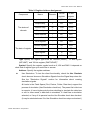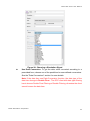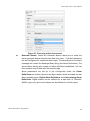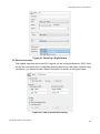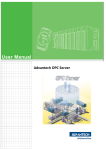
1
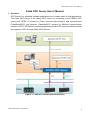
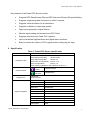
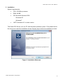
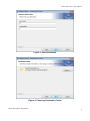
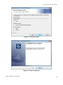
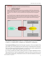
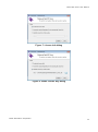
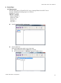
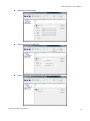
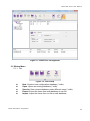
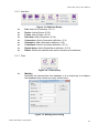
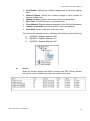
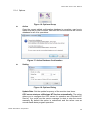
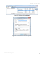
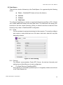
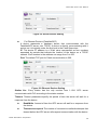
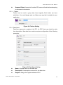
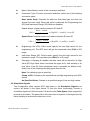
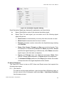
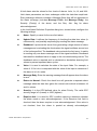
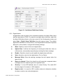
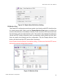
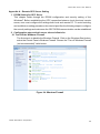
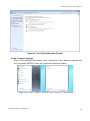
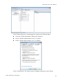
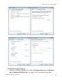
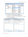
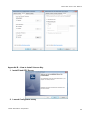
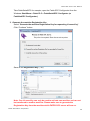
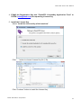
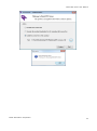
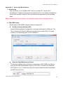
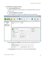
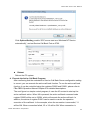
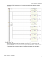
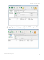
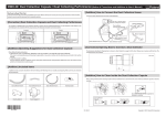
Fatek OPC Server User’s Manual V1.2 30 Jun. 2015 FATEK Automation Corporation Fatek OPC Server User Manual Table of Contents Table of Contents ................................................................................................................... 2 Tables ....................................................................................................................................... 4 Figures...................................................................................................................................... 5 1. Overview ........................................................................................................................... 6 2. Specification.................................................................................................................... 7 3. Installation ....................................................................................................................... 8 4. Quick Start ..................................................................................................................... 13 4.1 Data Access .......................................................................................................... 13 4.2 Data Conversion .................................................................................................. 16 4.3 Simulation Signal ................................................................................................ 18 4.4 Alarm and Event .................................................................................................. 19 4.5 Mutiply .................................................................................................................... 20 5. Fatek OPC Configurator ............................................................................................. 22 5.1 Ribbon Menu......................................................................................................... 23 5.1.1 File ................................................................................................................ 23 5.1.2 Add Item ....................................................................................................... 24 5.1.3 Tools ............................................................................................................. 24 5.1.4 Options ......................................................................................................... 26 5.2 Fatek Space .......................................................................................................... 28 5.2.1 Ports.............................................................................................................. 28 5.2.2 Devices ......................................................................................................... 28 5.2.3 Folders.......................................................................................................... 30 5.2.4 Data Items.................................................................................................... 30 5.3 Data Conversions ................................................................................................ 34 5.4 Simulation Signals .............................................................................................. 35 5.5 Alarm Definitions ................................................................................................. 36 5.5.1 Limit Alarms ................................................................................................. 36 5.5.2 Digital Alarms .............................................................................................. 38 5.6 Monitor View ......................................................................................................... 39 Appendix A – Remote OPC Server Setting .................................................................. 40 1. DCOM Setting for OPC Server ......................................................................... 40 2. Configuration steps at both server site and client site. ............................ 40 2.1 Turn-Off the Windows Firewall ............................................................. 40 2.2 My Computer settings ............................................................................. 41 FATEK Automation Corporation 2 Fatek OPC Server User Manual 3. Configuration steps at server site .................................................................. 45 3.1 OpcEnum Setting ..................................................................................... 45 3.2 Fatek OPC Server Setting....................................................................... 47 Appendix B -- How to Install License Key.................................................................... 49 1. Install Fatek OPC Server ................................................................................... 49 2. Launch Configurator Utility .............................................................................. 49 3. Generate the machine Registration Key ....................................................... 50 4. E-Mail the Registration Key and “FatekOPC LicenseKey Application Form” to FATEK ([email protected]) for requesting License Key .......................................... 51 5. Install the License Key ....................................................................................... 51 Appendix C – Active Call Back Service ........................................................................ 53 1. Introduction .......................................................................................................... 53 2. FBs-CBEH Setup ................................................................................................. 53 3. FatekNet OPC Configurator Setting ............................................................... 54 4. Execute the Active Call Back Program .......................................................... 55 5. OPC Client Test.................................................................................................... 56 FATEK Automation Corporation 3 Fatek OPC Server User Manual Tables Table 1: Fatek OPC Server specification ......................................................................................... 7 Table 2: Register Address Assignment .......................................................................................... 31 FATEK Automation Corporation 4 Fatek OPC Server User Manual Figures Figure 1: Fatek OPC Server System Structure .............................................................................. 6 Figure 2: Installation Welcome .......................................................................................................... 8 Figure 3: User Information ................................................................................................................. 9 Figure 4: Choosing Destination Folder ............................................................................................ 9 Figure 5: Ready to Install ................................................................................................................. 10 Figure 6: Setup Completed .............................................................................................................. 10 Figure 7: License Info dialog ........................................................................................................... 12 Figure 8: Install License Key dialog ............................................................................................... 12 Figure 9: Pop-up Menu of Tree View ............................................................................................. 22 Figure 10: Pop-up Menu of List View ............................................................................................. 22 Figure 11: Fatek OPC Configurator ................................................................................................ 23 Figure 12: File Group ........................................................................................................................ 23 Figure 13: Add Item Group .............................................................................................................. 24 Figure 14: Tools Group ..................................................................................................................... 24 Figure 15: Multiply Item Dialog ....................................................................................................... 24 Figure 16: Options Group ................................................................................................................ 26 Figure 17: Active Database Confirmation ...................................................................................... 26 Figure 18: Options Dialog ................................................................................................................ 26 Figure 19: Windows Service Manager ........................................................................................... 27 Figure 20: FatekSerialOPC Service Properties ............................................................................ 27 Figure 21: Ports Setting ................................................................................................................... 28 Figure 22: Serial Devices Setting ................................................................................................... 29 Figure 23: Ethernet Devices Setting .............................................................................................. 29 Figure 24: Folders Setting................................................................................................................ 30 Figure 25: Data Items Setting.......................................................................................................... 30 Figure 26: Choosing a Simulation Signal ...................................................................................... 32 Figure 27: Choosing a Data Conversion ....................................................................................... 33 Figure 28: Choosing a Digital Alarm ............................................................................................... 34 Figure 29: Data Conversions Setting ............................................................................................. 34 Figure 30: Simulation Signals Setting ............................................................................................ 36 Figure 31: Limit Alarm Definitions Setting ..................................................................................... 38 Figure 32: Digital Alarm Definitions Setting................................................................................... 39 Figure 33: Monitor View ................................................................................................................... 39 Figure 34: Windows Firewall ........................................................................................................... 40 Figure 35: Turn-Off the Windows Firewall ..................................................................................... 41 FATEK Automation Corporation 5 Fatek OPC Server User Manual Fatek OPC Server User’s Manual 1. Overview OPC Server is a standard software application and is widely used in field applications. The Fatek OPC Server is the classic OPC server for connecting to the FBs/B1z PLC series from FATEK. It is based on Fatek communication protocol, and includes serial (FatekSerialOPC) and ethernet (FatekNetOPC) servers for different communication interface of PLC. SCADA and customize applications with OPC client can directly access the registers of PLC through Fatek OPC Servers. Figure 1: Fatek OPC Server System Structure FATEK Automation Corporation 6 Fatek OPC Server User Manual Key features of the Fatek OPC Server include: Supports OPC Data Access (DA) and OPC Alarm and Event (AE) specifications. Supports engineering data conversion to client’s request. Supports value simulation for all data items. Supports multiplier to create tags quickly. Tags can be grouped in logical folders. Remote tag browsing and access from OPC Client. Supports read and write Fatek PLC registers. User could define high/low Alarm and digital alarm condition. Easy to monitor the values of PLC registers after configuring the tags. 2. Specification Table 1: Fatek OPC Server specification Item Compliance with Communication Characteristics OPC Data Access (DA) Version 1.0 OPC Data Access (DA) Version 2.05A OPC Data Access (DA) Version 3.0 OPC Alarm and Event(AE) Version 1.10 OPC Complex Data Version 1.0 OPC Common Definitions and Interfaces Version 1.0 Serial Ethernet Support PLC Support Registers FatekSerialOPC FatekNetOPC FBs Series B1/B1z Series Input discrete X/WX/DWX Output relay Y/WY/DWY Internal relay M/WM/DWM Step relay S/WS/DWS Timer discrete T/WT/DWT Counter discrete C/WC/DWC Timer register RT/DRT Counter register RTC/DRTC Data register R/DR Data register D/DD File register F/DF FATEK Automation Corporation 7 Fatek OPC Server User Manual 3. Installation System requirements: CPU: 233 MHz processor RAM: 64 MB OS: Microsoft Windows 2000 Windows-XP Windows7 .NET Framework 3.5 or latter version The Fatek OPC Server runs on PC with Windows operation system. First please launch the setup.exe to start the installation wizard. Step by step to finish the installation process. Figure 2: Installation Welcome FATEK Automation Corporation 8 Fatek OPC Server User Manual Figure 3: User Information Figure 4: Choosing Destination Folder FATEK Automation Corporation 9 Fatek OPC Server User Manual Figure 5: Ready to Install Figure 6: Setup Completed FATEK Automation Corporation 10 Fatek OPC Server User Manual ATTENTION: There are two application included in each Fatek OPC Server: Fatek OPC Configurator Run-Time OPC Server Before connecting with Fatek OPC Server by using SCADA or OPC Client, please launch the Fatek OPC Configurator to off-line configure the database(*.mdb) for Run-Time OPC Server first. Then “Active” (5.1.4) the mdb file after setting and close the configurator tool. Run-Time OPC Server is registered on Windows System after installation. When OPC Client connects with the server, user does not need to launch the configurator. Run-Time OPC Server will launch automatically, and access the register data of PLC according to the Active mdb database. After installation, please open the Fatek OPC Configurator from the Windows Start Menu > Fatek PLC > FatekSerialOPC Configurtor (or FatekNetOPC Configurator). The License Info Dialog will show first if the legal License Key (*.flk) is not installed. Click “Trail” button, user could evaluate the trial version directly to test without the License Key. The License Key is generated by Fatek, and it is according to the machine registration file (*.frk) from the PC device which Fatek OPC server will run on. If you have purchased the product, please generate the machine registration file first. Then email the file to Fatek for requesting the License Key. When you get the key from Fatek, please install the key. The standard version will unlock the limitation and functions. FATEK Automation Corporation 11 Fatek OPC Server User Manual Figure 7: License Info dialog Figure 8: Install License Key dialog FATEK Automation Corporation 12 Fatek OPC Server User Manual 4. Quick Start 4.1 Data Access Read the R0 register of Fatek FBs PLC device through Fatek Serial OPC Server. System condition and setting steps are as follows. Local Port: COM1 FBs PLC Settings: Station Number: 1 Baud rate: 9600 Parity: Even Data bits: 7 Stop bits: 1 Launch FatekSerialOPC Configurator How to add item Select the target tree node in tree view area. 1). Right-Click and choose a New item in menu. 2). Or click the button in “Add Item” group of Ribbon menu. FATEK Automation Corporation 13 Fatek OPC Server User Manual Add a port named COM1 Add a new device named FBs Add a new folder named Group1 (The step is not required.) FATEK Automation Corporation 14 Fatek OPC Server User Manual Add a new data item. Click Monitor button to test the data item R0. After testing, please close the monitor view to disconnect Fatek Serial OPC Server. Then you can still edit the database. FATEK Automation Corporation 15 Fatek OPC Server User Manual 4.2 Data Conversion By 4.1 conditions, if you would like to scale the R0 data value, the steps show how to do. Add a new Data Conversion definition named MyConversion. Check “Use Data Conversion”, and choose MyConversion FATEK Automation Corporation 16 Fatek OPC Server User Manual Open Monitor to test and you could see the converted value of R0. Before converting: R0 = 10 After converting: R0’= 0.1 𝑅0−0 ′ Formula: R0 = 1000−0 × (10 − 0) + 0 = 0.1 After testing, please close the monitor view to disconnect Fatek Serial OPC Server. Then you can still edit the database. FATEK Automation Corporation 17 Fatek OPC Server User Manual 4.3 Simulation Signal By 4.1 conditions, if you would like to test R0 before connecting with PLC physically, the steps show how to do. Check “Use Simulation”, and choose one of the simulation signals in the list. Beside default simulation signals, user also could create a new one. Please refer to 5.4. Open Monitor to test and you could see the simulation signal value. FATEK Automation Corporation 18 Fatek OPC Server User Manual 4.4 Alarm and Event By 4.1 conditions, if you would like to use OPC Alarm and Event function, the steps show how to configure the settings. Add a new Limit Alarm definition. Check “Generate Alarms”, define “Message Prefix” and choose an alarm condition. FATEK Automation Corporation 19 Fatek OPC Server User Manual By using 3rd party OPC Alarm and Event Client, the client would get alarm messages from Fatek OPC Server when R0 value achieved the alarm conditions. 4.5 Mutiply By 4.1 conditions, if you would like to create huge items by a template quickly (Ex:R0-R9), the steps show how to configure the settings. Select the target tree node in tree view area. Right-Click and choose a Mutiply in menu or click the Mutiply button in “Tools” group of Ribbon menu. Configure all parameters in Multiply Items dialog (5.1.3). Then click OK. FATEK Automation Corporation 20 Fatek OPC Server User Manual The 10 items (R0-R9) have been created in Group1. FATEK Automation Corporation 21 Fatek OPC Server User Manual 5. Fatek OPC Configurator Fatek OPC software system includes database configurator and run-time OPC server. Before connecting to OPC Server, you need to configure the OPC data structure first. The run-time server will create its data item space according to the structure when started. The configurator utility includes four regions. Database Space View: It is shown as tree view in left region. The database structure can be configured by mouse pop-up menu. Figure 9: Pop-up Menu of Tree View New: Create a subitem into the selected item. Multiply: Trigger the Multiply function to duplicate the selected item. Delete: Delete the selected item and all its subitems. Subitems View: The list view is located in right region. It shows the subitems of the selected tree node information. Double click the item in list view, the configuration view will show its setting page. Figure 10: Pop-up Menu of List View Select All: Select all items of list view. Delete: Delete the selected item and all its subitems. Adjust Listview: Adjust the column width to fit the contents. Properties View: It shows detail properties setting of the selected item. There are two buttons in each configuration view. Restore: Click the Restore button to reset current setting. Apply: Click the Apply button to confirm the setting. Monitor View: Start Fatek OPC Server and monitor the values of data items under the selected device node or folder node. FATEK Automation Corporation 22 Fatek OPC Server User Manual Figure 11: Fatek OPC Configurator 5.1 Ribbon Menu 5.1.1 File Figure 12: File Group New: Create a new configuration database (*.mdb). Open: Opens an existing database (*.mdb). Save As: Save current database under different name (*.mdb). Export: Export the items from mdb database to csv file. Import: Import the items from csv file to mdb database. FATEK Automation Corporation 23 Fatek OPC Server User Manual 5.1.2 Add Item Figure 13: Add Item Group Port: Add a Port interface. (5.2.1) Device: Add a Device. (5.2.2) Folder: Add a Folder. (5.2.3) Data Item: Add a Data Item. (5.2.4) Conversion: Add a Conversion definition. (5.3) Simulation: Add a Simulation definition. (5.4) Limit Alarm: Add a Limit Alarm definition. (5.5.1) Digital Alarm: Add a Digital Alarm definition. (5.5.2) Delete: Delete the selected item which includes its all subitems. 5.1.3 Tools Figure 14: Tools Group Multiply Duplicate the selected item into database. It is a simple way to configure the database where there are many similar items. Figure 15: Multiply Item Dialog FATEK Automation Corporation 24 Fatek OPC Server User Manual First Number: Specify the number to appear next to the first multiplied item. Numeric Places: Specify the minimum length of each number to append to Base text. Number of Items: Specify how many items to be generated. Base Text: The starting name of generated item. First Address: Register address assigned to the first item generated Address Increment: Increment count for each new address Item Name: Path to data item in the tree view. The result of the example shown in Multiply Item Dialog is as the following: 1). MyR0000: Register Address=100 2). MyR0001: Register Address=101 3). MyR0002: Register Address=102 Monitor Show the monitor window and start to connect the OPC Server. Monitor will get the value of data items under the selected tree node. FATEK Automation Corporation 25 Fatek OPC Server User Manual 5.1.4 Options Figure 16: Options Group Active Once the current edited configuration database is complete; user has to make sure that it is set to active. Next time the run-time server will use the database for all of its operations. Figure 17: Active Database Confirmation Setting Figure 18: Options Dialog Update Rate: Set the update frequency of the monitor view items. OPC server starts as a Windows NT Service automatically: The option allows you to configure the OPC server for operation as a Windows NT Service. You could use the service manager to start or stop the server manually. By default the option is unchecked, and the server runs as normal stand-alone program operation. FATEK Automation Corporation 26 Fatek OPC Server User Manual Figure 19: Windows Service Manager Figure 20: FatekSerialOPC Service Properties FATEK Automation Corporation 27 Fatek OPC Server User Manual 5.2 Fatek Space There are four levels of hierarchy in the Fatek Space. It is organized by the following terms. Ports Devices Folders Data items (FatekNetOPC does not have the feature.) To configure Fatek Space is similar to organized directories and files on PC. A folder can contain additional folders and also data items. The data items are always the branches in the tree control hierarchy. What you should note here is that the Ports hierarchy only exists in FatekSerialOPC configurator. 5.2.1 Ports Port is equivalent to a physical serial port in the computer. To correctly configure port means to setup serial port as a file name, baud rate, data bits, stop bits and parity scheme. Figure 21: Ports Setting 5.2.2 Devices For different communication Fatek OPC Server, the devices hierarchy and setting have a little difference in each configurator. For Serial Devices (FatekSerialOPC) Every device is connected to particular port, so it logically creates second level in the Fatek Space tree. FATEK Automation Corporation 28 Fatek OPC Server User Manual Figure 22: Serial Devices Setting For Ethernet Devices (FatekNetOPC) A device represents a hardware device that communicates with the FatekNetOPC server over TCP/IP. A device is directly communicating with it socket, so it is logically under the first level in the Fatek Space tree. IP: The device IP address is a 32-bit value represented as four numbers separated by periods that indicate the location of the device on a TCP/IP network. Each number in the address can range from 0 to 255. Port: The default TCP port for Fatek communication is 500. Figure 23: Ethernet Devices Setting Station No.: Every station has the only number from 1~254. OPC server communicates with PLC according to the station number. Timeout: Timeout parameters specify the period of time the server will wait for a response from the device: Read/Write: Amount of time the OPC server will wait for a response from the device. Timeouts to suspend: The number of consecutive read/write attempts that timeout before the OPC server will suspend communication with the device. FATEK Automation Corporation 29 Fatek OPC Server User Manual Suspend Period: Amount of time the OPC server will wait before attempting to reconnect to the device. 5.2.3 Folders Folders can be used to group data items logically. Each folder can have subfolders. You could design and use folders any way that is suitable to your application. Figure 24: Folders Setting 5.2.4 Data Items Data Item represents a register in the PLC. An OPC client can obtain the data item description. New data item creation requires configuration of the following properties: Figure 25: Data Items Setting Name: A logical name for the data item. Description: A descriptive comment for the data item. Register: Assign the register address of PLC. FATEK Automation Corporation 30 Fatek OPC Server User Manual Table 2: Register Address Assignment 16 bits Component Name Discrete register 32 bits register Input discrete X WX DWX Output relay Y WY DWY The status of Internal relay M WM DWM discrete Step relay S WS DWS Timer discrete T WT DWT Counter discrete C WC DWC Timer register - RT DRT Counter register - RC DRC Data register - R DR Data register - D DD File register - F DF The data of register Type: Specify the register type such as “Discrete (BOOL)”, “16 bits register (INT/UINT)” and “32 bits register (DINT/UDINT)”. Symbol: Specify the register symbol such as X, WX and DWX. It depends on what kind of register type you would like to access. Address: Specify the register address. Use Simulation: To test the client functionality, check the Use Simulate check box and choose a Simulation Signals from the Signal drop-down list. See the "Simulation Signals" section for information about creating simulation signals. All levels in the Fatek Space (Port, Device, Folder, Data Item) support the process of simulation (Use Simulation check box). The parent list in the tree is superior; it has a higher priority when deciding to simulate the data item or not. In other words, a data item is simulated, if it itself has a simulation selected, or if any of its parents has the Use Simulate check box checked. (It may be simulated even if its Use Simulation check box stays unchecked.) FATEK Automation Corporation 31 Fatek OPC Server User Manual Figure 26: Choosing a Simulation Signal Use Data Conversion: To get the data value converted according to a prescribed form, choose one of the predefined or user-defined conversions. See the "Data Conversions" section for more details. Note: If the data item use Data Conversion function, the data type of the data item change to Double Float。The OPC client with data type filtering has to choose Double Float Filtering or Disable Filtering, otherwise the client cannot browse the data item. FATEK Automation Corporation 32 Fatek OPC Server User Manual Figure 27: Choosing a Data Conversion Generate Alarms: Check the Generate Alarms check box to make the server generate alarms based on the data item value. ; it will be followed by the text configured for a particular alarm type. The second part of the alarm message will contain the Message Body string (see Alarm Definitions). The server allows having any number of alarm definitions predefined. You can then combine one of them with the specific tags. Alarm parameters are set up in the Configurator under the Alarm Definitions tree control, shown in the figure below, which is divided into two alarm template types: Digital Alarm Definitions and Limit (analog) Alarm Definitions. Digital alarms can be defined for a data item of “Discrete” (BOOL) type only, while Limit alarms can be defined for all other types. FATEK Automation Corporation 33 Fatek OPC Server User Manual Figure 28: Choosing a Digital Alarm 5.3 Data Conversions The original data item value from PLC register can be converted by server. OPC client will get the converted value of data item directly without any calculation. Before using conversion, you should create a Data Conversion, as shown in the figure below. Figure 29: Data Conversions Setting FATEK Automation Corporation 34 Fatek OPC Server User Manual Name: Specifies the name of the conversion definition. Conversion Type: For each conversion definition, select one of the following conversion types: None (make float): Converts the data into float data type, but does not change the value itself. When this option is selected, the Engineering Unit (EU) and Instrument Range (IR) fields are disabled. Linear: Keeps a linear relation between EU and IR. CVal = 𝑅𝑉𝑎𝑙 − 𝐿𝑜𝑤𝐼𝑅 × (𝐻𝑖𝑔ℎ𝐸𝑈 − 𝐿𝑜𝑤𝐸𝑈) + 𝐿𝑜𝑤𝐸𝑈 𝐻𝑖𝑔ℎ𝐼𝑅 − 𝐿𝑜𝑤𝐼𝑅 Square Root: Keeps a square root relation between EU and IR. CVal = √ 𝑅𝑉𝑎𝑙 − 𝐿𝑜𝑤𝐼𝑅 × (𝐻𝑖𝑔ℎ𝐸𝑈 − 𝐿𝑜𝑤𝐸𝑈) + 𝐿𝑜𝑤𝐸𝑈 𝐻𝑖𝑔ℎ𝐼𝑅 − 𝐿𝑜𝑤𝐼𝑅 Engineering Unit (EU): Client scale; specify low and high values for the engineering unit. The OPC client will get the converted value (CVal) in EU range. Instrument Range (IR): Device scale; specify low and high values for the instrument range. The raw data value (RVal) is in IR range. Clamping: If clamping is enabled, the data value will be limited to its High Value (EU High Value when it exceeds the upper limit), and similarly to its Low Value (Low EU Value parameter when it exceeds the bottom limit). Select one of the following clamping types from the list: None: No clamping type is specified. Clamp on EU: Clamps on the specified low and high engineering units (EU) values. As Specified Value: Clamps on a specified range of low and high values. 5.4 Simulation Signals The Configurator offers various OPC data items in the Simulation Signals tree control, as shown in the figure below. To test the client functionality, choose a simulation signal from the tree control. All levels in the Fatek Space folder support the process of simulation. The parent list in the tree control is superior; it has higher priority when deciding to simulate the data item or not. FATEK Automation Corporation 35 Fatek OPC Server User Manual Figure 30: Simulation Signals Setting Each Simulation Signal type has specific parameters, as shown below. Name: Specifies the name of the selected simulation signal. Signal Type: For each signal, you can select one of the following signal types from the list: Read Count is incremented by one every time when the item is read. Write Count increments when the item is written. Random generates random value within the Amplitude range starting with Position. Ramp, Sine, Square, Triangle and Step are periodical signals. Their time behavior is influenced by Period and Phase parameters. Period specifies the signal frequency (in milliseconds), while Phase moves the signal origin on the time axis (in degrees). Square and Triangle have one additional parameter: Ratio. Ratio defines Triangle signal steepness, or Square signal H/L proportions. The Number of Steps parameter of the Step signal defines the number of steps into which the signal amplitude will be divided. 5.5 Alarm Definitions The Fatek OPC Server is also an OPC Alarm and Events server that supports the following alarm types: 5.5.1 Limit Alarms To create a new limit alarm definition, right-click the Alarm Definitions folder on the tree control of the Configurator and select New - Limit Alarm Definition from the pop-up menu. FATEK Automation Corporation 36 Fatek OPC Server User Manual A limit alarm sets the values for four levels of alarms: LoLo, Lo, Hi, and HiHi. Limit alarm parameters can have subranges within the data item amplitude. Every subrange definition includes a Message Body that will be appended to the alarm message (includes Message Prefix and Message Body), the Severity (Priority) of the alarm, and the Req. Ack. flag for alarm acknowledgement. In the Limit Alarm Definition Properties dialog box, shown below, configure the following settings: Name: Specify a name for the new limit alarm. Update Rate: It defines the frequency of checking the data item value (in milliseconds), and possibly responding by sending the alarm message. Deadband: It prevents the server from generating a huge amount of alarm messages and overloading the clients when the signal oscillates around one of the limits specified. The deadband value extends the limit zone. It results in sending only one alarm message even if the signal oscillates. Deadband indicates the deadband value to apply to the converted analog values. The deadband value is required and is calculated on borderline alarming limit values to prevent repeated alarm cycles. Value: It is used to calculate the state of the input fields. For example, a value of 10 for LoLo is compared with the value of the input to determine if the alarm is in LoLo state. Message Body: Enter the warning message that will appear when the alarm is sent. Return to Normal: Check the check box will generate a separate alarm message when the data item gains the normal value which is between Hi and Lo values. Severity: It is the OPC-defined value for alarm Priority. The valid OPC severity range is 0 (lowest) to 1000 (highest). Requires Ack: It is used for OPC condition alarms to determine whether the alarm needs a user acknowledgement. If the Requires Ack field is checked, then the alarm requires a user acknowledgement. If the value is not checked, then the alarm is posted as already acknowledged. FATEK Automation Corporation 37 Fatek OPC Server User Manual Figure 31: Limit Alarm Definitions Setting 5.5.2 Digital Alarms A digital alarm sets an alarm if the comparison between the Alarm State Value and the input state is TRUE. To create a new digital alarm definition, right-click the Alarm Definitions folder on the tree control of the Configurator screen and select New - Digital Alarm Definition from the pop-up menu. The default digital alarm definition is shown below. In the Digital Alarm Definition Properties dialog box, shown below, configure the following settings: Name: Specify a name for the new digital alarm. Update Rate: It defines the frequency of checking the data item value (in milliseconds), and possibly responding by sending the alarm message. Enable: Check the check box will enable the digital alarm definition. Value: Specify a value for the digital alarm (True or False). Message Body: Enter the warning message that will appear when the alarm is sent. Return to Normal: Check the check box will generate a separate alarm message when the data item gains the opposite value. Severity: It is the OPC-defined value for alarm Priority. The valid OPC severity range is 0 (lowest) to 1000 (highest). Requires Ack: It is used for OPC condition alarms to determine whether the alarm needs a user acknowledgement. FATEK Automation Corporation 38 Fatek OPC Server User Manual Figure 32: Digital Alarm Definitions Setting 5.6 Monitor View The Fatek OPC configurator provides a monitor view function with OPC client function for viewing server data. When push the Display Monitor View button on toolbar, the monitor view will show in the bottom of screen. It will connect to OPC server and scan the data items under the selected tree node. The monitor view displays the data item values and OPC quality information such as timestamp, quality status and limit field. User can easily and instantly test the configuration. Pop the Display Monitor View button will disconnect the OPC server after monitoring. Note: Please close the Monitor View before editing. It makes sure that the OPC server will use the newest setting before starting. Figure 33: Monitor View FATEK Automation Corporation 39 Fatek OPC Server User Manual Appendix A – Remote OPC Server Setting 1. DCOM Setting for OPC Server This chapter walks through the DCOM configuration and security setting of the Windows7. Before establishing the OPC connection between local client and remote server, user must configure the settings both local and remote PC. To avoid troubling and multifarious setting procedure, this tutorial specifies the following steps to configure the security settings and make sure the OPC DCOM communication can be established. 2. Configuration steps at both server site and client site. 2.1 Turn-Off the Windows Firewall The first step is to disable the Windows Firewall. Click on the Windows Start button; select the Control Panel->Windows Firewall. Choose the “Turn off Windows Firewall (not recommended)” radio button. Figure 34: Windows Firewall FATEK Automation Corporation 40 Fatek OPC Server User Manual Figure 35: Turn-Off the Windows Firewall 2.2 My Computer settings Click on the Windows Start button; enter “dcomcnfg” in the “Search programs and files” and press ENTER to open the Component Services window. Right-click on “My Computer” and choose the “Properties” from the menu. FATEK Automation Corporation 41 Fatek OPC Server User Manual Click “Default Properties” tab and apply the setting as the following figure. Check the “Enabe Distributed COM on this computer”. Set the “Default Authentication Level” to Connect. Set the “Default Impersonation Level” to Identify. Click “COM Security” tab. Step by step to configure permissions as the follows. FATEK Automation Corporation 42 Fatek OPC Server User Manual 1). In the Access Permissions group, click the “Edit Limits…” button. Add ANONYMOUS LOGON 、 Everyone 、 SYSTEM 、 NETWORK and INTERACTIVE to the list of “Group or user names”. Check Local Access and Remote Access to “Allow” status for all added items. 2). In the Access Permissions group, click the “Edit Default…” button. The setting is the same as step 1). FATEK Automation Corporation 43 Fatek OPC Server User Manual 3). In the Launch and Activation Permissions group, click the “Edit Limits…” button. Add ANONYMOUS LOGON、Everyone、SYSTEM、NETWORK and INTERACTIVE to the list of “Group or user names”. Set the Allow checkboxes of Local Launch, Remote Launch, Local Activation and Remote Activation checked for all added items. Check Local Launch, Remote Launch, Local Activation and Remote Activation to “Allow” status for all added items. FATEK Automation Corporation 44 Fatek OPC Server User Manual 4). In the Launch and Activation Permissions group, click the “Edit Default…” button. The setting is the same as step 3). 3. Configuration steps at server site 3.1 OpcEnum Setting FATEK Automation Corporation 45 Fatek OPC Server User Manual Select OpcEnum that is under “Component Services > Computers > My Computer > DCOM Config”, and right –click it and choose “Properties”. At General tab, set “Authentication Level” as None. At Location tab, check “Run application on this computer”. At Security tab, set “Launch and activation Pemissions” and “Access Pemissions” as Use Default. At Identity tab, set “The launching user”. FATEK Automation Corporation 46 Fatek OPC Server User Manual 3.2 Fatek OPC Server Setting Select the Fatek OPC Server that is under “Component Services->Computers>My Computer->DCOM Config”, and right –click it and choose “Properties”. FATEK Automation Corporation 47 Fatek OPC Server User Manual At General tab, set “Authentication Level” as Default. At Location tab, check “Run application on this computer”. At Security tab, set “Launch and activation Pemissions” and “Access Pemissions” as Use Default. At Identity tab, set “The launching user”. FATEK Automation Corporation 48 Fatek OPC Server User Manual Appendix B -- How to Install License Key 1. Install Fatek OPC Server 2. Launch Configurator Utility FATEK Automation Corporation 49 Fatek OPC Server User Manual Take FatekSerialOPC for example, open the Fatek OPC Configurator from the Windows Start Menu > Fatek PLC > FatekSerialOPC Configurtor (or FatekNetOPC Configurator). 3. Generate the machine Registration Key Select “Generate the machine Registration Key for requesting License Key”. Click “Continue” button. Save as the Registration Key (*.frk) Note: One License Key can only be used to activate one machine and can not be transferred to another machine. Please make sure to generate the Registration Key from the machine which FATEK OPC server will run on. FATEK Automation Corporation 50 Fatek OPC Server User Manual 4. E-Mail the Registration Key and “FatekOPC LicenseKey Application Form” to FATEK ([email protected]) for requesting License Key 5. Install the License Key Select “Install the License Key of this machine” Click “…” button to choose License Key file (*.flk). Click “Continue” button to install the License Key. FATEK Automation Corporation 51 Fatek OPC Server User Manual FATEK Automation Corporation 52 Fatek OPC Server User Manual Appendix C – Active Call Back Service 1. Introduction User would like to use FatekNet OPC Server to access PLC, but the PLC workstation’s IP address is acquired using dynamic IP or if it’s behind a firewall and access from outside is difficult. User can achieve the application by the following steps. Note: FatekNetOPC Server Version 1.0.4 and later support Active Call Back Service. 2. FBs-CBEH Setup Please refer to FBs-CBEH Operation Manual chapter 8-3. Get Device Serial Number (S/N) Launch Ethernet adaptor Configuration, and scan workstations in Ethernet. The last two number of Ethernet Address is device serial number (S/N). The serial number in the following figure is 1670 (0x0686H). Setup the Data Maintenance Center The Service CallBack Server Ethernet configuration of FBs-CBEH must be the same as the data maintenance center (ex:192.168.0.119) which the FatekNet OPC Server run on. It makes sure that the communication between workstation and OPC server is fine. FATEK Automation Corporation 53 Fatek OPC Server User Manual 3. FatekNet OPC Configurator Setting Install FatekNetOPC Server Install the FatekNetOPC Server application on PC (data maintenance center) (ex: 192.168.0.119). Setup FatekNetOPC Configurator Launch FatekNetOPC Configurator to configure the device and data items. Enable User Service Call Back, enter the device serial number (S/N) and Port. Click Option/Active, and click “Yes” to use the current edited database. FATEK Automation Corporation 54 Fatek OPC Server User Manual Click Options/Setting, enable “OPC server start as a Windows NT Service automatically”, and set Service Call Back Port as 5700. Reboot Reboot the PC system. 4. Execute the Active Call Back Program After confirming that the workstation’s Service Call Back Server configuration setting is correct, you can execute the active call back function. To use the active call back function, it can be controlled using the registers D3950 and D3951; please refer to FBs-CBEH Operation Manual Chapter 2 for detailed descriptions. The next figure is a simple control program; it uses the X0 contact to start up the active call back action. When X0 is pressed, the active call back command code register D3950 will be set to 3359H, which will execute the active call back. In addition, the status of register D3951 can be used to monitor the operation execution of the call back. In the example, when the connection is successful, Y1 will be ON. When connection failed, Y2 or Y3 will be ON. When connection is FATEK Automation Corporation 55 Fatek OPC Server User Manual terminated, D3951 must be set to 0 in order to accept the new call back request command. 5. OPC Client Test Before executing active call back program, even if the OPC client connect with FatekNetOPC Server, it cannot access the register data from PLC. It is because the FatekNetOPC Server does not get the IP address information from FBs-CBEH. FATEK Automation Corporation 56 Fatek OPC Server User Manual After executing active call back program, the FatekNetOPC Server get the IP from FBs-CBEH and make connection successfully. FATEK Automation Corporation 57