1
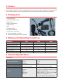
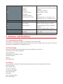
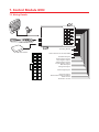
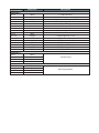
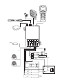
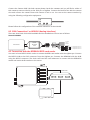
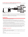
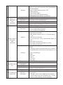
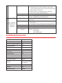
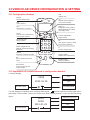
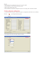
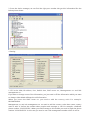
G91I Tracking Device User Manual | Version 2.00 TABLE OF CONTENTS 1. Preface 2. Packing List 3. Rating And Operating Conditions 4. General Specification 5. Features And Functions 3 3 3 3 4 5.1 Communication Mode..........................................................................................................4 5.2 Data Upload..............................................................................................................................4 5.3 Alarms.........................................................................................................................................4 5.4 Features......................................................................................................................................5 6. Preparation Before Installation 5 6.1 Installation steps and ways Check vehicle state before installation.....................6 6.2 Installation points to remember........................................................................................6 6.3 Disassemble components....................................................................................................6 6.4 Measure vehicle connection...............................................................................................7 6.5 Deciding on Components Location Control Module.................................................7 6.6 Finding the wires you need.................................................................................................8 7. Control Module G91I 10 7.1 Wiring Details........................................................................................................................10 7.2 Side View.................................................................................................................................13 7.3 Bottom View...........................................................................................................................13 7.4 Connection Diagram of Installation...............................................................................14 8. Connector J204 for Camera CM9600I or AD9600 or HUB GHUB-232 15 8.1 J204 Connections for the Camera..................................................................................15 8.2 J204 Connection f or AD9600 (Analog interface).....................................................16 8.3 Connection with the RFID9600 RFID card reader......................................................16 8.4 J204 Connection for CAN9600 J1939/J1708 (CAN interf ace)..............................17 9. Attention 17 9.1 LED flash state explanation...............................................................................................17 9.2 Common phenomena.........................................................................................................18 10.Get Ready To Use 11.User Commands 12.Default Parameter 13.Vehicular Device Configuration & Setting 13.1 Configuration Handset....................................................................................................20 13.2 Explanation of contents showed in configuration handset................................20 13.3 Use configuration handset to configure....................................................................21 13.4 Use software to configuration.......................................................................................22 18 18 19 20 1.Preface This installation guide is used for related people from distributor, agent or factory to understand the correct wire connection of our GOS-G91I series so that user can save time and avoid problems. 2. Packing List 1. Control Module 2. General Wiring Harness 3. Panic Button 4. GPS Active Antenna 5. GSM Antenna 6. MIC 7. Starter kill relay 8. Installation Manual 9. Hand Phone (optional) 10. LCD Text Display (optional) 11. Camera with image process(optional) 3. Rating and Operating Conditions Parameter Min Max Units Supply Voltage (12V) 9 14 V Supply Voltage (24V) 21 Power consumption 30 (sleep) 180 (transmit) mA Operation Temp. -30 70 ºC Storage Temp. -40 85 ºC Operating Humidity 50 90 % V 4. General Specification Specification Physical Specifications Power Supply Dimension 98 x 68 x 43 mm Weight 100 g IP Rating IP62 Voltage 9-35V DC Power Consumption 180mA (Active) 30mA (Sleep) uBlox LEON-100 Quad Band Cellular Modem Class 10 (4 downlink, 2 uplink, max. 5) GPRS Mobile Station Class B Approvals AT&T, R&TTE, CE, GCF, FCC, PTCRB, Antenna Anatel, IC, China SRRC, etc External (SMA) Internal (Optional) External (SMA) Internal (Optional) GPS Antenna uBlox NEO 6M (GPS, Galileo & Sbase) Receiver engine Channels 50 Parallel Channels Position Accuracy Autonomous <2.5M Sensitivity -162dBm Navigation update 1sec Time to first fix (TTFF) Snap Start 0.3 sec, Hot Start 1 sec Warm Start 15 sec, Cold Start 27 sec Backup Battery Type Rechargeable 500mAh Lion Ignition, Engine, Door, Panic I/O Digital Input Button, Positive trigger1, Positive Digital Output trigger2,Negative Triger1, Negative trigger2 Starter kill, parking light, Camera Environment Optional Accessories Operating Temperature -30℃to +70℃ Humidity 5% – 90% LCD display Hand Phone Camera. 5. Features and functions 5.1 Communication Mode: The system can transmit the data in two different modes. SMS, GPRS The system can be selected either both modes at same time or single mode. The system can also be selected for the GPRS/TCP or GPRS/UDP mode. 5.2 Data Upload: There are many kinds of data upload options are available in the system: Upload by interval (Static/Dynamic) Upload by Events Upload by Turn (Change Course) Upload by Alarms Polling Heart Beat Data 5.3 Alarms: The system has many kind of alarm reporting depending on the configuration of device. Power Off Alarm Harsh brake Alarm Geo-Fence IN Alarm Geo-Fence Out Alarm User Define Alarm Rob Alarm Route Deviation Alarm Door open alarm 5.4 Features: Remote Configuration: there are remote configuration functions in this system, users can send command to vehicles by SMS or GPRS Real time tracking: Users can track their vehicles in real time. Intelligent power Management. Gradual Immobilizer. Record Buffer: Data buffer to transfer the data after GPRS connectivity. Backup Battery: rechargeable battery 350mAH LiON Zone management: 64 Hardware based Geo-fences are available to manage the zone freely. Routes: user can set up to 8 routes for each vehicle. Mileages: it can show the linear distance from original place to destination. Read Data counter: Can read data counter to know how much data device has sent. Watch Dog: Internal watch dog to avoid any hang up in the device Driving Record 6. Preparation before installation a. Get main unit from warehouse, and open package to check if there are all the assemblies. b. Get SIM card from user which should be network card with call number display, voice call and GPRS internet functions. c. Prepare tools and spare assembly. Common tools and spare assembly are as the following: a) 4-edge screw driver b) 2-edge screw driver c) No.5 to No. 22 sleeves d) nipper e) key f) cutting pliers g) cutter h) scissor i) 6-edge sleeve j) plastic plunge k) 3M damp proof insulation plaster l) 502 glue m) 3M bubble double plaster n) multipurpose water o) towel p) brush q) dustproof set of car chair r) 12V electric pen s) Multi-meter t) IN5401 diode u) electric iron v) soldering tin w) power wire 6.1 Installation steps and ways Check vehicle state before installation a. Get key from owner and enter car to check appearance and all the systems including ignition, sound, air-condition, door switch, trunk control or original alarm system. If there are some problems, confirm with owner and fill the result in the access network form and after you get signature from owner then start installation. b. Get confirmation from owner whether owner has special requirement for device installation position, whether original alarm system need to be removed. Record all these information. For top grade car, if car system is so complicated that functional wires of this system cannot be installed, you should explain clearly and get confirmation from owner. c. If the car is a new one and no parts were taken apart before, if possible you should tell owner which parts will be removed in case misunderstanding happens. d. Get SIM card which should have call number display, voice call and GPRS internet functions from owner for test. e. Check if windshield has explosion-proof and heat insulation diaphragm which will affect receiving of GPS signal and so that it can not get the longitude and latitude; if not, then hide GPS antenna in dashboard and ensure there is no metal things above it; if it has this diaphragm, then you need to hide the GPS antenna in front and at the back of bumper. 6.2 Installation points to remember a. Important! Please read this entire installation guide before beginning the installation. The installation of this GPS/GPRS system interfacing with many of the vehicle's system. Many new vehicles use low-voltage or multiplexed systems that can be damaged by low resistance testing devices, such as test lights and logic probes (computer safe test lights). Test all circuits with a high quality digital multi-meter before making connections. b. Don't disconnect the battery if the vehicle has an anti-theft-coded radio. If equipped with an air bag, avoid disconnecting the battery if possible. Many airbag systems will display a diagnostic code through their warning light after they lose power. Disconnecting the battery requires this code to be erased, which can require a trip to the dealer. c. Check with the customer on status LED location. d. Remove dome light fuse. This prevents accidentally draining the battery. e. Roll down a window to avoid being locked out of the car. 6.3Disassemble components a. Disassemble components including sound plug, sound, sundries box, baffle at the sides of center control board that are required to remove for installation. b. Check the inner structure of dashboard and decide the position to install control module, which are usually put under dashboard or inside the pillar after removing the seat belt. c. Pay attention to airbag connection and other connections when disassembling. d. Be sure no parts will get lacerated or dirty when disassembling. e. When disassembling, if you are not familiar with sound system, please do not pull out wire in case it will lock. f. If engine has lock code, the removal of power is forbidden. 6.4 Measure vehicle connection a. Roll down the windows. b. Find the proper position for control module, and check the length of input wires and power wires. c. Make sure input wires will not interfere with original wires. And before you cut connection wire of fuel pump or ignition power wires, be sure it is required. d. When vehicle is with manual engine off, extra electric wind is needed. e. When measuring, you should take out key and pay more attention to vehicle with airbag and do not touch wire group of this system. f. To avoid damage of vehicle computer, do not use energy consumption electric pen to test induction wires of vehicle computer. g. Do not remove power of top-grade car. h. If meter of top-grade car displays fault indication, please report to supervisor and turn to professional electrician. 6.5 Deciding on Components Location Control Module Never put the control module in the engine compartment! The first step in hot-wiring a vehicle is removing the driver's side under-dash panel to access the starter and ignition wires. If the control module is places just behind the driver's side dash it can easily be disconnected. When location the control module, try to find a secure location that will not require you to extend the harnesses wires. Keep it away from heater core ( or any other heat sources) and any obvious leaks. Some good control module locations: Under the dash, inside the seat belt pillar etc. 6.5.1GPS Antenna Never put the GPS antenna in the engine compartment! The GPS antenna must be installs in such a location that no metal parts are located above it. It is extremely important to clean, with alcohol, the surface to which the GPS antenna is to be attached. Keep away from heat and must he installed in such away that it faces the sky to receive the correct coordinates. It is better to install it under the dash board, inside the front grill, or back of the car. 6.5.2Starter Kill Relay If starter kill relay or its connections are immediately visible upon removal of the under-dash panel, they can easily be bypassed. Always make the relay and its connections difficult to discern from the factory wiring! Exposed yellow butt connectors do not look like factory parts, and will not fool anyone! For this reason, routing and starter kill wires away from the steering column is recommended. 6.5.3SOS Button Ensure that the location you pick for the switch has sufficient clearance to the rear. The switch should be well hidden and it should be places so passenger cannot accidentally hit it. 6.6Finding the wires you need IMPORTANT: Do not use a 12V test light to find these wires! All testing is described using a digital multimeter. 6.6.1Obtaining Constant 12V We recommend two possible sources of 12V constant: the (+) terminal of the battery, or the constant supply to the ignition switch. Always install a fuse within 12 inches of this connection. If the fuse also will be powering other circuits, such as power windows, door locks, etc.; Fuse accordingly. IMPORTANT: Do not remove the fuse holder on the red wire. It ensures that the control module has its own fuse, of the proper value, regardless of how many accessories are added to the main power feed. 6.6.2Finding the 12V switched ignition wire The ignition wire is powered when the key is in the run or start position. This is because the ignition wire powers the ignition system (spark plugs, coil) as well as the fuel delivery system (fuel pump, fuel injection computer). Accessory wires lose power when the key is in the start position to make more current available to the starter motor. 6.6.3How to find (+)12V ignition with your multi-meter: I. Set DCV or DC voltage (12V or 20V is fine). II. Attach the (-) probe of the meter to chassis ground. III. Probe the wire you suspect of being the ignition wire. The steering column harness or ignition switch harness is an excellent place to find this wire. IV. Turn the ignition key switch to the run position. If your meter reads (+) 12V, go to the next step. If it doesn't, probe another wire. V. Now turn the key to the start position. The meter display should stay steady, not dropping by more than a few tenths of a volt. If it drops close to or all the VI. Way to zero, go back to step 3. If it stays steady at (+) 12V, you have found an ignition wire. 6.6.4Finding the accessory wire An accessory wire will show +12V when the key is in accessory and run position. It will not show +12V during the cranking cycle. There will often be more than one accessory wire in the ignition harness. The correct accessory wire will power the vehicle's climate control system. Some vehicles may have separate wire for the blower motor and the air conditioning compressor. In such cases, it will be necessary to add a relay to energize the second accessory wire. 6.6.5Finding the door pin switch circuit The best places to find the door switch wire are: At the pin switch: When testing at the pin switch, check the wire to ensure that it "sees" all the doors. Often, the passenger switch will cover all the doors even if the drivers switch will not. At the dome light: This may not be your best choice if the vehicle has delayed dome light supervision, but it will work in many Hondas, or any vehicle with completely diode-isolated pin switches. Once you have determined the wire color, the easiest place to connect to the wire is often at the kick panel, at the windshield pillar, or in the running board. When an easy location is not available, running a wire to the dome light itself is often the best solution. 6.6.6How to find a door pin switch trigger wire with your multi-meter: i. Set to DCV or DC voltage (12V or 20V is fine). ii. In most Fords, faster the (-)probe of the meter to chassis ground. If in most other cars, faster the (+) probe of your meter (+)12V constant. iii. Probe the wire you suspect of being the door trigger wire. If the meter reads iv. (+)12V when any door is opened, you have found a trigger wire. Note: Make sure the wire you use "sees" all the doors! Some newer GM vehicles lack standard-type pin switches. The dome light in these vehicles is turned on when the door handle is lifted. These usually have a blue/white or white coming out of the door into the kick panel which will provide a (-) trigger for all doors. Some GM vehicles (some Cavaliers, Grand Ams, etc.) Have a yellow wire coming out of the door which provides a (+) door trigger. 6.6.7Making your wire connections Before making your connections, plan how your wires will be routed through the vehicle. For instance, the yellow ignition input, the red 12V constant input, will often be routed together to the ignition switch harness. In order to keep the wiring neat and make it harder to find, you may wish to wrap these wires together in electrical tape or conceal them in tubing similar to what the manufacturer used. There are two acceptable ways of making a wire connection: Solder connections and crimp connectors. When properly performed, either type of connection is reliable and trouble-free. Regardless of whether you solder your connections or you use mechanical-type crimp-on connections, ensure that all connections are mechanically sound and that they are insulated. Cheap electrical tape, especially when poorly applied, is not a reliable insulator. It often falls off in hot weather. Use good quality electrical tape or heat shrink. Never twist-and-tape the wires together without soldering. Never use "fuse taps", as the can damage fuse box terminals. If you use tapping connectors such as 3M T-tapes (not to be confused with Scotch-Loks), avoid using them in higher-current applications (constant 12V, ground, etc.). Some tapping connectors are inferior in quality and should be avoided. 7. Control Module G91I 7.1 Wiring Details Speaker GSM Antenna Receiving Module GPS Antenna 红2 黑1 白4 灰3 空6 空5 空8 棕7 橙10 蓝9 紫12 黄11 灰14 绿13 黑16 黑白 15 J204 Connector for Camera/CanBus Panic Button Input+ Green Positive 2 Input+ Grey Negative 2 InputYellow Positive 1 Input+ Purple Negative 1 InputBlue ACC Input+ Orange Door InputBrown Engine Input+ Grey Siren OutputWhite Fuel & Power Cut OutputBlack GroundRed Power +9V-35V Wire Number Connector 1 Wire 1 Wire 2 Wire 3 Wire 4 Wire 5 Wire 6 Wire 7 Wire 8 Wire 9 Wire 10 Wire 11 Wire 12 Wire 13 Wire 14 Wire 15 Wire 16 Wire Color Description Black Red Grey White (-) Input Ground (+)12V constant power supply (+) Output for the siren (-) Output Engine/Fuel cut (Immobilizer) Brown (+) Input Engine Sensor Blue Orange Yellow Purple Green Grey White/Black Black (+) Input Ignition or ACC (-) Input Door Sensor (+) Input Positive 1 (-) Input Negative 1 (+) Input Positive 2 (-) Input Negative 2 Panic Button Panic Button Connector 2 Wire 1 Wire 2 Wire 3 Wire 4 Black Blue Red Green Camera Input Connector 3 Wire 1 Wire 2 Wire 3 Wire 4 Black Blue Red Green Receiving Module Speaker GSM Antenna Handset GPS Antenna Wireless Module Panic Button J204 Turning Light Yellow High Voltage Wire Blue Red Green Brown M Door Switch Orange Blue Alternator Door Light IC ON ACC Yellow Green Purple Grey B+ START 7.2 Side View Hand Phone or Text Display: Connect the hand phone or Text Display using the RJ45 connector. Microphone: Connect the supplied MIC to the MIC jack. When needed, this MIC will allow the control center to rear the voices inside the vehicle. Green LED: This LED will show the connection of GPRS. If this LED blinks very fast more than 4 times a second this means the control unit has successfully establish The GPRS connection with the control center. If this LED blinks slowly this means the GPRS connection with the control center still not established. In this case you need to check the configuration of APN, IP and SIM card. Be sure that the SIM card used in the control module is not PIN code protected. Yellow LED: This LED will show the status of GPS signals. If this LED continuously ON this means control module has fixed GPS signals. GPS Antenna If it is blinking this means it the GPS module is trying to receive the GPS signal from satellite. GSM Antenna GPS Antenna: Connect the supplied GPS antenna to the control unit with correct connector. You may find the word of GPS written near the Antenna connector. GPRS Status LED Configuration Handset/Text Display GSM Antenna: Connect the supplied GSM antenna to the control unit with correct GPS Status LED connector. You may find the word of GPRS written near the Antenna connector. 7.3 Bottom View SIM Card Jacket: Open the cover on the back of the unit as shown in the picture. After opening the cover please insert the SIM card inside the SIM jacket and close the cover. NOTE: Before inserting the SIM card please GOS-9601SZ make sure that the SIM card is active. It has necessary balance, GPRS services are already MC45 530880-88306-A100-1 350450414851819 9641111995 activated, SIM can send and receive the short messages. Device ID: Sticker on the bottom of the unit mentioned the device ID. This ID is a unique number issued by Gosafe. Device ID SIM Card Jacket IMEI Number IMEI: Sticker on the bottom of the unit mentioned the IMEI number of the Modem used in the device. 7.4 Connection diagram of installation Connector RJ 45 Input The RJ45 connector is a multipurpose connector. This can be used for the following: 7.4.1 Configuration Handset or Cable Connect the configuration handset of the cable as per following picture. Handset 7.4.2 Connection with TD-9600 Connect the TD-9600 with the RJ45 connector as following picture. LCD display area OK OK UP DOWN CLR CLR Remote Signal Receive Area 7.4.3 Connection for MDT-9600 Power Connector MIC Speaker Rj45 8. Connector J204 f or Camera CM9600I or AD9600 or HUB Ghub-232 This is RS232 connector which can be used to connect the camera or CAN interface or Analog device or RS232 hub. 8.1 J204 Connections for the Camera Connect the camera directly with the J204 connector. If you would like to connect more than one camera then you need to order special camera which can connects with at least 4 extra cameras. The connection with the other cameras is very simple. Connect the Camera ONE (the hub camera please checks the cameras and you will find a sticker of Hub camera) connects directly to the J204 port of vigilant. Connect the Camera Two with the camera One and connect the camera three with camera 3 and so on. You can set the camera number by using the following configuration equipment. Please follow the configuration of the cameras manual for further details. 8.2 J204 Connection f or AD9600 (Analog interface) There are three kind of AD-9601 available and the installation of those are as follows: Normal AD9600 4 9 8 7 Gosafe Control Unit AD-9600 V-8.0 Yellow Grey Brown Orange 1 Temperature Sensor 1 2 Temperature Sensor 2 3 Temperature Sensor 3 8.3 Connection with the RFID9600 RFID card reader You need to have RS232 HUB in order to connect the RFID card reader with the vigilant pro. Connect the RS232 HUB to the J203 connector from the Vigilant pro. Connect the RFID9600 with the HUB using the RS232 connector. The device will read the card whenever in contact with the RFID9600 reader and sends the ID number to the server. RS232 Hub RFID Reader 8.4 J204 Connection for CAN9600 J1939/J1708 (CAN interf ace) If you have ordered the dual protocol CAN-9600 which can support J1939/71 and J1708/J1587 protocol then please follow the following installation diagram. J1939 CAN Low 120Ohm Resistor J1939 CAN High +12V J1708 CAN B GND CAN-9600 J1939/J1708 J1708 CAN A Data availability is depended on the truck or bus you are connecting the interface. Gosafe can’t predict which data is available on J1939/71 and which data is available on J1708/J1587. The truck manufacturers are changing the data in different regions. Please contact your local truck or bus dealer to get the more information about the data availability. 9.Attention 1. Be sure the car window is open during testing. 2. If main unit restart automatically or start the car after engine off, this is because low spare battery and it will get right after 24 hours after installation which can be judged by the following method: first monitor center send command to engine off and then start vehicle, if it is very difficult to start, it means low battery; if it can start normally, check brown engine induction wire. Be sure it is not in alarm state when checking. 3. If brown engine off wire is connected with power wire of charge indicator or fuel pump when break, electricity character of brown wire is that voltage is 0 and current is 0 and resistor value is 5-20 ohm with cathode. There are several possibilities when brown wire voltage is 12V: 1) can not make vehicle power off 2) can start vehicle after break 3) can not release vehicle from cutoff. 4. Do not connect white wire (ACC induction wire) to circuit which electricity character will change when on drive. If install incorrectly it will cause the damage of central control system. 9.1 LED flash state explanation 1. Green light a. Flash slowly, 1 second is on while 1 second is off and it has no GSM signal b. Flash fast, 0.5 second is on while 1 second is off and it has GSM signal b. Keep on flashing fast, 0.2 second is on while 0.2 second is off and GPRS is working and sending data. 2. Yellow light a. Flash slowly, 1 second is on while 1 second is off and it has no GPS signal b. Flash fast, 0.5 second is on while 1 second is off and it has GPS signal from one to three satellites. b. Keep on flashing. It means it has received GPS signal from four or more than four satellites and successfully GPS position. 9.2 Common phenomena 1. No display in hand phone if nonuse for some time 2. Reason: device is in sleep status to save power. 3. Method: ACC ON and make an incoming call 4. Arm unsuccessfully 5. Reason: car door is not lock properly and ACC is ON. 10.Get ready to use 1. Fill all the information in the internet access installation form, such as information of vehicle owner and vehicle. And show vehicle owner the filled form and get the authorization and signature which means installation has been finished. 2. Give vehicle back to owner to use. 3. Inform monitor center it is ready to use and the content of the installation form. 4. Give the original copy of the installation form and driver license and copy of ID card or corporation license to monitor center. 11.User Commands The user can use following commands in order to receive the location and immobilize the vehicle. These commands must be send by any mobile number and contain the password for each command. The commands must be sent in SMS format to the device SIM card. When the device receives these messages it respond to these messages according to the command and also replay back to the number which sent this command. Command Format 1 Immobilization (SMS command) Parameter description Remark Password,IMB,M Default Password 000000 • password is the user's password • M: value of 0 means release the immobilizer (the vehicle will able to start if you send command with 0) M: Value 1 means immobilize the vehicle. (The vehicle will not able to start the engine if you send this command with 1) The default setting for the immobilizer disables. If this setting is not change to enable the user can't immobilize the vehicle. It is recommended that Control center or Admin of the web software must enable the immobilizer setting. Example Changing User Password 2 (sms command) Sending command Parameter description Remark Example Sending Command Parameter description Remark Query Location Information 3 (SMS command) Example Set SMS center No. 4 Sending command Parameter description Remark Example Sending command 5 Set checking IP and Port NO. Parameter description Send: 000000, IMB, 1 Reply of successful Implementation: IMMOBILIZER SET SUCCESSFUL Reply of failure Implementation: SET UNSUCCESSFUL Send: 000000, IMB, 0 Reply of successful Implementation: IMMOBILIZER RESUME SET SUCCESSFUL old_password, UPW, M, New_password • password is the user's password • M: value of 1 Set new Password Password length must be 6 digit (0-9) Send: 000000, UPW, 1, 123456 Reply: CLIENT PASSWORD IS 123456 Password, PRQ, M • password is the user's password • M=0 It means LBS information • M=1 It means with hyperlink MCC: Mobile country code, 3 decimal digits, e.g. 232 Value 000: not decoded MNC: Mobile network code, 2 or 3 decimal digits, e.g. 03 Value 000: not decoded LAC: Location area code, 4 hexadecimal digits, e.g. 3010 Value 0000: not decoded CID Cell ID, 4 hexadecimal digits, e.g. 4EAF Value 0000: not decoded Send: 123456,PRQ,1 Reply: http:maps.google.com/staticmap?zoom=14&size=2 00x200&markers=39.949328,116.3875&sensor=fals e Send: 123456,PRQ,0 Reply: MCC=460 MNC=1 LAC=517A CID=1FB1 Password, SCN, scn_number Country code should add into the SMS center No. Send: 467233, SCN, 8613800200500 Answer: SCN:8613800200500 Password,TIP,M,IP_addr,Port,Redial_Times 1. M=0 is to check parameters; M=1 is to set parameters 2. IP_addr: control center GPRS server IP address, the IP address must be separated by"#", no full stop or other delimiter can be used here. 3. Port: control center GPRS server monitor port NO; Redial_Times: The total times device will continuously redial Control Center if previous dial failed. Value range:5-255 4. Redail_Times<5, default setting is 5, Redail_ Times=255 means unlimited times Remark example Sending command Parameter 6 Set checking APN, PAP user name and password description Remark example send: 467233,TIP,1,114,142,154,28,1212,5 answer: IP&PORT:114.142.154.28:1212 Password,APN,M,apn_name, pap_name,pap_ password 1. M= 0 is to check parameters, M=1 is to set parameters 2. The length of apn_name,pap_name,pap_password must be less than 32 bytes, can't use "," Send : 467233,APN,1,cmnet,, Answer: APN:cmnet PAP_NAME: PAP_PASSWORD: 12.Default Parameter Description Setting Auto Tracking OFF Auto input trigger response OFF Tracking interval 0sec Group ID 0 Speed Limit OFF Geo-Fence OFF Trigger Option OFF Receive calls Enable Outgoing Calls Enable Call limited option Disable GPRS IP Set as per provided by customer TCP record mode Standard Mileage 0 km SMS send mode Normal 13.VEHICULAR DEVICE CONFIGURATION & SETTING 13.1 Configuration Handset LCD display area Record Nonuse temporarily Up Choose menu upwards or increase number Dial call or answer Hang-up Hang up incoming call or finish operation and back to standby state OK enter menu or confirm Down Choose menu downwards or decrease number Volume adjustment Adjust volme Numerical Area Input number Clr clear input number or back to previous operation * Search longitude and latitude, speed and driving direction # Nonuse temporarily Hotline Dial service hotline number Check number System test reserved key Set Set of system functional menu Earphone jack Plug in earphone Ring buzzer ring of incoming call and message 13.2 Explanation of contents showed in configuration handset 1. Startup display: 00:00 2011-01-01 No GPS Signals Time Date No GSM Signals 2. It will display as following after receiving GSM signal " "shows intensity of GSM signal and it will display "China mobile", which you can get from GSM service provider, or you can when receiving signal. 00:00 No GPS Signals GSM service provider 00:00 Time 2011-01-01 Date Have GSM Signals 3. It will display as following after receiving GPS signal from more than 4 satellites: " " shows it can position. 00:00 GSM service provider 00:00 Time 2011-01-01 Date Have GPS Signals Have GSM Signals 13.3 Use configuration handset to configure 13.3.1 SMS Center Number (Message Center Number): Press the "set" button of the handset for a moment after it goes into the setting interface. Input the number, for example, 8613800200500, which you can get from GSM service provider or you can insert this SIM card to your mobile to check from the message setting. 86 is the country code. It must be include the country code. Press “OK” button to save, it will go to the next step Management number setting 13.3.2 Management number Management number is a control SIM card; the device will only recognize this number when you send command to it. It's convenient to set the test person's mobile number to management number. Input the number without country code. Press "OK" button to save it and go to the next step Hotline setting. Note: some country need to add "0" before the number when people send message or call. For example, a Pakistan phone number "13423562356". When you send message to this mobile you need to input the phone number "013423562356". In this case you need to set a Sub management number which is use for assisting to control the device. The Sub Management Number should be set as "013423562356". 13.3.3 Hotline It's the number which can receive the call from device. it can automatically pick-up. 13.3.4 Set the APN through SMS. APN is the access point of network. The command to set the APN is *HQ,1234,S24,123456,2,CMNET# "CMNET" is the APN. You just need to change this information when you send the command. For example, you APN is "internet", you just send *HQ,1234,S24,123456,2,internet# 13.3.5 Set the IP and Port through SMS. The command to set the IP and port is *HQ,1234,S23,12 3456,126,136,10,1,3030,5# "126,136,10,1" is the IP, "3030" is the Port, "5" means redial time 5 seconds. For example your IP is "54.12.20.1" and Port is "5050". When you want to change the IP and port you just need to change IP and port, no need to change other information. You can send command like this *HQ,1234,S23,12 3456,54,12,20,1,5050,5# Remark: 1. Case-sensitive. For example the "HQ" and "S" must be capital. 2. All the separator of the command must be comma. 3. SMS coding method: PDU mode. 4. The command is composition of digital. It must be 7 bit coding, other command is invalid. 13.4 Use software to configuration 1. Connect the device with your computer through our configuration cable then run our software. Click this you will get the below picture. 2. Go to page 3 and choose the right COM port number. 3. From the device manager, we can find the right port number. We get this information like the below picture shows. 4. Setting 1. Fill in the APN, IP address, Port, Redial time, SMS center no., Management no. and Sub management no... If you want to change some of the information, you just need to fill the information which you want to change. Other blank will keep the old information. When you inser t the SMS center no. you need to add the countr y code. For example. 8613800200500. Management no. and sub management no. no need to add the country code. Note: some country need to add "0" before the number when people send message or call. For example, a Pakistan phone number "13423562356". When you send message to this mobile you need to input the phone number "013423562356". In this case you need to set a Sub management number which is use for assisting to control the device. The Sub Management Number should be set as "013423562356". 2. Single click program button 1) If it pop-up "com port fail!" means the COM port is used by other software or not exist. 2) If it pop-up "Send data failed!" means program fail. 3) If it pop-up "Send finish!" means programing successful. Change another device to program. Repeat the 3 and 4 steps to program other device. Note: · When you are doing the settings, please make sure the device have 12V power. · There are three pages parameters you can choose to set. Just press the 'Next' button to choose them and set. · When you insert the SMS center no. or the management no., you need to add the country code. · To use our trackers on our own software, anytracking. We only need to set the APN.