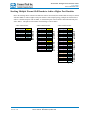
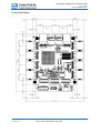
1
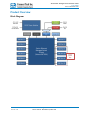
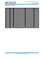
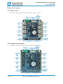
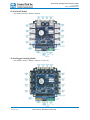
Xtreme/GbE Managed Carrier Ethernet Switch Users Guide Connect Tech Inc. 42 Arrow Road Guelph, Ontario N1K 1S6 www.connecttech.com CTIM-00429 Revision 0.05 12/15/2015 Tel: 519-836-1291 Toll: 800-426-8979 (North America only) Fax: 519-836-4878 Email: [email protected] [email protected] Xtreme/GbE - Managed Carrier Ethernet Switch Users Guide www.connecttech.com Table of Contents ` Table of Contents ................................................................................................................................ 2 Preface................................................................................................................................................... 4 Disclaimer .......................................................................................................................................................4 Customer Support Overview ...........................................................................................................................4 Contact Information ........................................................................................................................................4 Limited Product Warranty ............................................................................................................................... 5 Copyright Notice .............................................................................................................................................5 Trademark Acknowledgment ..........................................................................................................................5 ESD Warning ..................................................................................................................................................6 Revision History .................................................................................................................................... 6 Introduction........................................................................................................................................... 7 Product Overview .................................................................................................................................. 8 Block Diagram ................................................................................................................................................8 Ordering Part Numbers ...................................................................................................................................9 Connector Locations ..................................................................................................................................... 10 8-Port RJ-45 Models........................................................................................................................... 10 8-Port Rugged Latching Models ......................................................................................................... 10 12-Port RJ-45 Models ......................................................................................................................... 11 12-Port Rugged Latching Models ....................................................................................................... 11 Detailed Feature Pinouts and Descriptions ........................................................................................... 12 10/100/1000 Ethernet RJ-45 Connector ........................................................................................................ 12 10/100/1000 Ethernet Rugged Latching Connector ...................................................................................... 12 External LED Connectors ............................................................................................................................. 13 IDC Serial Management Connector (RJ-45 Models) .................................................................................... 14 Rugged Locking Serial Management Connector (Rugged Models) .............................................................. 14 System Jumper Block .................................................................................................................................... 15 PC/104 Connector (XDG005, 008) ............................................................................................................... 16 PCIe/104 Connector (XDG006, 009, 010) .................................................................................................... 16 Input Power Connector .................................................................................................................................. 17 On-board Indicator LEDs (8-Port Models) ................................................................................................... 18 On-board Indicator LEDs (12-Port Models) ................................................................................................. 18 CLI Management Interface .................................................................................................................. 19 CLI Access via External Serial Port .............................................................................................................. 19 CLI Access via PCIe/104 Bus ....................................................................................................................... 19 CLI Basics ..................................................................................................................................................... 20 Complete CLI and Protocol Configuration Reference Guide ........................................................................ 20 Web Management Interface ................................................................................................................. 21 Accessing the Web Management Interface ................................................................................................... 21 Web Management Interface Overview .......................................................................................................... 22 Complete Web Protocol Configuration Reference Guide ............................................................................. 22 Factory Default Configuration ............................................................................................................. 23 Hardware Usage Examples .................................................................................................................. 24 Instructions for Standalone Operation ........................................................................................................... 24 Instructions for Installation in PCIe/104 Stack .............................................................................................. 24 Document: CTIM-00429 Revision: 0.05 Page 2 of 35 Connect Tech Inc. 800-426-8979 | 519-836-1291 Date: 12/15/2015 Xtreme/GbE - Managed Carrier Ethernet Switch Users Guide www.connecttech.com Stacking Multiple Xtreme/GbE Boards to Achieve Higher Port Densities ................................................... 25 Thermal Details ................................................................................................................................... 26 XDG Thermal Parameters ............................................................................................................................. 26 Air Cooled Heatsinks .................................................................................................................................... 26 Conduction Cooled Heatplate ....................................................................................................................... 26 Mechanical Details ............................................................................................................................... 27 3D STEP Models ........................................................................................................................................... 27 2D Dimension Drawings ............................................................................................................................... 27 8-Port RJ-45 Models........................................................................................................................... 27 8-Port Rugged Model ......................................................................................................................... 28 12-Port RJ-45 Model .......................................................................................................................... 29 12-Port Rugged Model ....................................................................................................................... 30 Cable Details ........................................................................................................................................ 31 Cables Kits.......................................................................................................................................... 31 RJ-45 panel mount to 10-pin MiniTek w/Latch - CBG117 ........................................................................... 32 RJ-45 panel mount to RJ-45 - P115-012 ....................................................................................................... 33 DB-9 to 10-pin IDC cable – CAG104 ........................................................................................................... 34 DB-9 to 10-pin MiniTek w/Latch - CBG127 ................................................................................................ 35 Document: CTIM-00429 Revision: 0.05 Page 3 of 35 Connect Tech Inc. 800-426-8979 | 519-836-1291 Date: 12/15/2015 Xtreme/GbE - Managed Carrier Ethernet Switch Users Guide www.connecttech.com Preface Disclaimer The information contained within this user’s guide, including but not limited to any product specification, is subject to change without notice. Connect Tech assumes no liability for any damages incurred directly or indirectly from any technical or typographical errors or omissions contained herein or for discrepancies between the product and the user’s guide. Customer Support Overview If you experience difficulties after reading the manual and/or using the product, contact the Connect Tech reseller from which you purchased the product. In most cases the reseller can help you with product installation and difficulties. In the event that the reseller is unable to resolve your problem, our highly qualified support staff can assist you. Our support section is available 24 hours a day, 7 days a week on our website at: www.connecttech.com/sub/support/support.asp. See the contact information section below for more information on how to contact us directly. Our technical support is always free. Contact Information Mail/Courier Connect Tech Inc. Technical Support 42 Arrow Road Guelph, Ontario Canada N1K 1S6 Email/Internet [email protected] [email protected] www.connecttech.com Note: Please go to the Download Zone or the Knowledge Database in the Support Center on the Connect Tech website for product manuals, installation guides, device driver software and technical tips. Submit your technical support questions to our customer support engineers via the Support Center on the Connect Tech website. Telephone/Facsimile Technical Support representatives are ready to answer your call Monday through Friday, from 8:30 a.m. to 5:00 p.m. Eastern Standard Time. Our numbers for calls are: Toll Free: 800-426-8979 (North America only) Telephone: 519-836-1291 (Live assistance available 8:30 a.m. to 5:00 p.m. EST, Monday to Friday) Facsimile: 519-836-4878 (on-line 24 hours) Document: CTIM-00429 Revision: 0.05 Page 4 of 35 Connect Tech Inc. 800-426-8979 | 519-836-1291 Date: 12/15/2015 Xtreme/GbE - Managed Carrier Ethernet Switch Users Guide www.connecttech.com Limited Product Warranty Connect Tech Inc. provides a lifetime Warranty for the Xtreme/GbE - Managed Carrier Ethernet Switch. Should this product, in Connect Tech Inc.'s opinion, fail to be in good working order during the warranty period, Connect Tech Inc. will, at its option, repair or replace this product at no charge, provided that the product has not been subjected to abuse, misuse, accident, disaster or non-Connect Tech Inc. authorized modification or repair. You may obtain warranty service by delivering this product to an authorized Connect Tech Inc. business partner or to Connect Tech Inc. along with proof of purchase. Product returned to Connect Tech Inc. must be pre-authorized by Connect Tech Inc. with an RMA (Return Material Authorization) number marked on the outside of the package and sent prepaid, insured and packaged for safe shipment. Connect Tech Inc. will return this product by prepaid ground shipment service. The Connect Tech Inc. Limited Warranty is only valid over the serviceable life of the product. This is defined as the period during which all components are available. Should the product prove to be irreparable, Connect Tech Inc. reserves the right to substitute an equivalent product if available or to retract the Warranty if no replacement is available. The above warranty is the only warranty authorized by Connect Tech Inc. Under no circumstances will Connect Tech Inc. be liable in any way for any damages, including any lost profits, lost savings or other incidental or consequential damages arising out of the use of, or inability to use, such product. Copyright Notice The information contained in this document is subject to change without notice. Connect Tech Inc. shall not be liable for errors contained herein or for incidental consequential damages in connection with the furnishing, performance, or use of this material. This document contains proprietary information that is protected by copyright. All rights are reserved. No part of this document may be photocopied, reproduced, or translated to another language without the prior written consent of Connect Tech, Inc. Copyright 2015 by Connect Tech, Inc. Trademark Acknowledgment Connect Tech, Inc. acknowledges all trademarks, registered trademarks and/or copyrights referred to in this document as the property of their respective owners. Not listing all possible trademarks or copyright acknowledgments does not constitute a lack of acknowledgment to the rightful owners of the trademarks and copyrights mentioned in this document. Document: CTIM-00429 Revision: 0.05 Page 5 of 35 Connect Tech Inc. 800-426-8979 | 519-836-1291 Date: 12/15/2015 Xtreme/GbE - Managed Carrier Ethernet Switch Users Guide www.connecttech.com ESD Warning Electronic components and circuits are sensitive to ElectroStatic Discharge (ESD). When handling any circuit board assemblies including Connect Tech COM Express carrier assemblies, it is recommended that ESD safety precautions be observed. ESD safe best practices include, but are not limited to: Leaving circuit boards in their antistatic packaging until they are ready to be installed. Using a grounded wrist strap when handling circuit boards, at a minimum you should touch a grounded metal object to dissipate any static charge that may be present on you. Only handling circuit boards in ESD safe areas, which may include ESD floor and table mats, wrist strap stations and ESD safe lab coats. Avoiding handling circuit boards in carpeted areas. Try to handle the board by the edges, avoiding contact with components. Revision History Revision Date Changes 0.00 11/19/2013 Original 0.01 11/28/2013 Added Stacking Multiple Xtreme/GbE Section 0.02 01/09/2013 Corrected pinout of P2 for XDG007/8/9 Products 0.03 04/25/2014 Added XDG010 Information 0.04 09/01/2014 Corrected Cable Drawings 0.05 12/15/2015 Major Release Update: - Changed to CTI latest template - Updated all photos and connector call outs - Added additional CLI and Web Configuration info - Added Conduction Cooled Info Document: CTIM-00429 Revision: 0.05 Page 6 of 35 Connect Tech Inc. 800-426-8979 | 519-836-1291 Date: 12/15/2015 Xtreme/GbE - Managed Carrier Ethernet Switch Users Guide www.connecttech.com Introduction Connect Tech’s Xtreme/GbE Managed Carrier Ethernet Switch provides high density, high port count, Carrier Grade Ethernet switching capabilities in an extremely small embedded form factor. Excellent for any space constrained, mission-critical application needing an embedded high-density/high-port count managed Ethernet Switch. Feature Description Ethernet Switch Engine Vitesse VSC7428 (8-port Models) / VSC7429 (12-Port Models) Carrier Grade Ethernet Switch Chipset Memories Ports Magnetics I/O Connectors Layer 2 Switching Management Access Indicator LEDs Standalone Operation Input Voltage Power Consumption Expansion Bus Interface Dimensions Weight MTBF Operating Temp Warranty and Support Document: CTIM-00429 Revision: 0.05 A powerful embedded 416 MHz RISC 32-bit CPU with DDR2 external memory and DMA-based frame extraction and insertion supports timing over packet, Ethernet OAM, and performance monitoring. 1Gb DDR2 SDRAM (125MB) 128Mb Serial NOR Flash (16MB) 8 or 12 x Gigabit Ethernet (10/100/1000 Mbps ) On-board Gigabit Magnetics for all Ports (No external Magnetics required) Designed for Long-haul Gigabit Ethernet (10/100/1000 Mbps) applications Ethernet: RJ-45 (8 or 12 Port Models), 2mm Pitch Locking Pin Headers (8 or 12 Port Models) Power: 3.5mm Pitch Terminal Block Header Console: 0.1” Pitch Header, 2mm Pitch Locking Pin Headers 802.1Q VLAN switch with 8K MACs and 4K VLANs Push/pop up to two VLAN tags IPv4/IPv6 multicast Policing with storm control and MC/BC protection RSTP and MSTP support Hardware and software-based learning Link aggregation (IEEE 802.3ad) Independent and shared VLAN learning (IVL, SVL) Jumbo frame support Web Interface CLI via RS-232 Software API SMNP PCIe/104 Bus (Option) 2 LEDs per port Power Rail LEDs Status LEDs Switch can be used as a standalone unit OR it can be paired with an embedded SBC. +9V to 36V Input Range (All Models) +12V only (Models with PCIe/104 Connector) +5V only (XDG029 Only) VSC7428: Idle: 0.3A, 3.6W Typical: 0.35A, 4.2W Max: 0.5A, 6W (with +12V input) VSC7428: Idle: 0.4A, 4.8W Typical: 0.5A, 6W Max: 0.75A, 9W (with +12V input) PCIe/104 bus (optional - sourcing power and management interface) 8-Port: 3.775” x 3.550” 12-Port: 4.393” x 4.550” Tallest Top Side Component: Heatsink 0.375” (9.5mm) Download 3D Model Here TBD TBD -40°C to +85°C (chipset rated to +125°C thermals) Lifetime Warranty and Free Technical Support Page 7 of 35 Connect Tech Inc. 800-426-8979 | 519-836-1291 Date: 12/15/2015 Xtreme/GbE - Managed Carrier Ethernet Switch Users Guide www.connecttech.com Product Overview Block Diagram 12-Port Models Only Document: CTIM-00429 Revision: 0.05 Page 8 of 35 Connect Tech Inc. 800-426-8979 | 519-836-1291 Date: 12/15/2015 Xtreme/GbE - Managed Carrier Ethernet Switch Users Guide www.connecttech.com Ordering Part Numbers Part Number XDG004 XDG005 XDG006 XDG007 XDG008 XDG009 XDG010 XDG012 XDG013 XDG016 XDG017 XDG018 XDG019 XDG020 XDG021 XDG022 XDG023 XDG029 XHG101 GbE Ports GbE Port Connector Type Thermal Solution 8 RJ-45's Air Cooled Heatsink 8 RJ-45's Air Cooled Heatsink 8 RJ-45's Air Cooled Heatsink 8 Rugged Locking Pin Headers Air Cooled Heatsink 8 Rugged Locking Pin Headers Air Cooled Heatsink 8 Rugged Locking Pin Headers Air Cooled Heatsink 12 RJ-45's & Ruggd Locking Pin Headers Air Cooled Heatsink 12 RJ-45's & Ruggd Locking Pin Headers Air Cooled Heatsink 12 Rugged Locking Pin Headers Air Cooled Heatsink 8 RJ-45's Conduction Cooled Heatplate 8 RJ-45's Conduction Cooled Heatplate 8 RJ-45's Conduction Cooled Heatplate 8 Rugged Locking Pin Headers Conduction Cooled Heatplate 8 Rugged Locking Pin Headers Conduction Cooled Heatplate 8 Rugged Locking Pin Headers Conduction Cooled Heatplate 12 RJ-45's & Ruggd Locking Pin Headers Conduction Cooled Heatplate 12 Rugged Locking Pin Headers Conduction Cooled Heatplate 12 Rugged Locking Pin Headers Conduction Cooled Heatplate 8 or 12 Port Conduction Cooled Heatplate (Standalone Item) Document: CTIM-00429 Revision: 0.05 Page 9 of 35 Connect Tech Inc. 800-426-8979 | 519-836-1291 Exp Bus Option None PC/104 PCIe/104 None PC/104 PCIe/104 PCIe/104 None PCIe/104 None PC/104 PCIe/104 None PC/104 PCIe/104 PCIe/104 PCIe/104 None (+5V Only) Date: 12/15/2015 Xtreme/GbE - Managed Carrier Ethernet Switch Users Guide www.connecttech.com Connector Locations 8-Port RJ-45 Models Part Numbers: XDG004, XDG005, XDG006, XDG016, XDG017, XDG018 8-Port Rugged Latching Models Part Numbers: XDG007, XDG008, XDG009, XDG016,XDG017,XDG018 Document: CTIM-00429 Revision: 0.05 Page 10 of 35 Connect Tech Inc. 800-426-8979 | 519-836-1291 Date: 12/15/2015 Xtreme/GbE - Managed Carrier Ethernet Switch Users Guide www.connecttech.com 12-Port RJ-45 Models Part Numbers: XDG010, XDG012, XDG022 12-Port Rugged Latching Models Part Numbers: XDG013, XDG023, XDG029 (no PCIe/104) Document: CTIM-00429 Revision: 0.05 Page 11 of 35 Connect Tech Inc. 800-426-8979 | 519-836-1291 Date: 12/15/2015 Xtreme/GbE - Managed Carrier Ethernet Switch Users Guide www.connecttech.com Detailed Feature Pinouts and Descriptions 10/100/1000 Ethernet RJ-45 Connector Function LAN Connector Locations P1-P8 (XDG004/5/6) P3A-J (XDG010) XDG Connector PN 7498111120 - Manufacturer: Wurth Mating Connector PN Standard Cat5e (8P8C RJ-45 Plug) Pinout Pin Signal 1 MX1P 2 MX1N 3 MX2P 6 MX2N 4 MX3P 5 MX3N 7 MX4P 8 MX4N Green Only = 1Gbps Green and Yellow = 100Mbps Yellow Only = 10Mbps 10/100/1000 Ethernet Rugged Latching Connector Function LAN Connector Locations P5A-H (XDG007/8/9) P4A-B (XDG010) XDG Connector PN 98424-G52-10LF - Manufacturer: FCI Mating Connector PN 10073599-010LF - Manufacturer: FCI Pinout Pin 1 2 3 4 5 6 7 8 9 10 Document: CTIM-00429 Revision: 0.05 Signal MX1MX1+ MX2MX2+ SHELL SHELL MX3MX3+ MX4MX4+ Description Ethernet Pair 1 Ethernet Pair 1 Ethernet Pair 2 Ethernet Pair 2 RJ Shell Connection RJ Shell Connection Ethernet Pair 3 Ethernet Pair 3 Ethernet Pair 4 Ethernet Pair 4 Top view Side view looking at connector Page 12 of 35 Connect Tech Inc. 800-426-8979 | 519-836-1291 Date: 12/15/2015 Xtreme/GbE - Managed Carrier Ethernet Switch Users Guide www.connecttech.com External LED Connectors Function External Port LEDs Locations P4 (XDG004-009) P5 (XDG010) XDG Connector PN DF20G-40DP-1V(56) - Manufacturer: Hirose Mating Connector PN DF20A-40DS-1C - Manufacturer: Hirose Pinout (XDG004-009) Pinout (XDG010) Document: CTIM-00429 Revision: 0.05 Page 13 of 35 Connect Tech Inc. 800-426-8979 | 519-836-1291 Date: 12/15/2015 Xtreme/GbE - Managed Carrier Ethernet Switch Users Guide www.connecttech.com IDC Serial Management Connector (RJ-45 Models) Function Serial Management Connector Locations P2 (8-Port Models) P6 (12-Port Models) Top view XDG TSW-105-08-L-D-RA - Manufacturer: Samtec Connector PN: Mating Any IDC 2x5 0.1” pitch female assembly. Connector PN: Pinout Pin Signal 1 - 2 - 3 RX 4 - 5 TX 6 - 7 - 8 - 9 GND 10 - Side view looking at connector Rugged Locking Serial Management Connector (Rugged Models) Function Serial Management Connector Locations P2 Top view XDG 98464-G61-10ULF - Manufacturer: FCI Connector PN: Mating 10073599-010LF - Manufacturer: FCI Connector PN: Pinout Document: CTIM-00429 Revision: 0.05 Pin Signal 1 - 2 RX 3 TX 4 - 5 GND 6 - 7 - 8 - 9 - 10 - Side view looking at connector Page 14 of 35 Connect Tech Inc. 800-426-8979 | 519-836-1291 Date: 12/15/2015 Xtreme/GbE - Managed Carrier Ethernet Switch Users Guide www.connecttech.com System Jumper Block Function System Jumper Block Locations J1 Type 2x3 (or 2x4) 2mm pitch Jumper Block Pinout (8-Port Models) Pos Signal Name Description A RESET# JUMPER ON = XDG goes into reset JUMPER OFF = XDG boots up normally Note: A reset button can be installed on these pins B TBD No functionality at this time C UART Source Select JUMPER ON = VSC7428 UART connects to PCIe/104 Bus (Only present on XDG006 and XDG009) JUMPER OFF = VSC7428 UART connects to External Management Port (P2) Pinout (12-Port Models) D TBD Pos Signal Name Description A TBD No functionality at this time B RESET# JUMPER ON = XDG goes into reset No functionality at this time JUMPER OFF = XDG boots up normally Note: A reset button can be installed on these pins C TBD No functionality at this time D UART Source Select JUMPER ON = VSC7428 UART connects to PCIe/104 Bus (Only present on XDG006 and XDG009) JUMPER OFF = VSC7428 UART connects to External Management Port (P2) Document: CTIM-00429 Revision: 0.05 Page 15 of 35 Connect Tech Inc. 800-426-8979 | 519-836-1291 Date: 12/15/2015 Xtreme/GbE - Managed Carrier Ethernet Switch Users Guide www.connecttech.com PC/104 Connector Function PC/104 Connector Locations P9, P10 (8-Port Models) Type PC/104 Stacking Connector Pinout Pinout compliant to PC/104 specification pinout. This connector is only used to source power for the board (+12V), all other pins will be pass-through. * Shown uninstalled Visit http://www.pc104.org to download the specification free of charge. PCIe/104 Connector Function PCIe/104 Connector Locations P9 (8-Port Models) P1 (12-Port Models) Type PCIe/104 Stacking Connector Pinout Pinout compliant to PCIe/104 specification pinout v2.01. The Xtreme/GbE connects its management port to the x1 PCIe Link of the PCIe/104 bus (Type-1 or Type-2). The Xtreme/GbE also uses the +12V power rail from the PCIe/104 bus to power the board. Visit http://www.pc104.org to download the specification free of charge. Document: CTIM-00429 Revision: 0.05 Page 16 of 35 Connect Tech Inc. 800-426-8979 | 519-836-1291 Date: 12/15/2015 Xtreme/GbE - Managed Carrier Ethernet Switch Users Guide www.connecttech.com Input Power Connector The Xtreme/GbE can be powered by EITHER an external 3.5mm pitch Phoenix style connector OR directly via the PC/104 or PCIe/104 bus. Powering via the Phoenix style connector is called standalone mode Powering via the PC/104 connector is called bus mode Standalone Power Requirements Minimum Voltage Maximum Voltage +9 VDC +36 VDC XDG029 – Power Requirements The XDG029, 12-Port Rugged Switch will accept a +5V input. Bus Mode Power Requirements Bus Connector PC/104 PCIe/104 Voltage Rail used +12V +12V External Input Power Connector Details Function Main Input Power +9V to +36V: All Models +5V Only: XDG029 Location P16 (8-Port Models) P7 (12-Port Models) 1843790 - Manufacturer: Phoenix Contact XDG Connector PN 1847055 - Manufacturer: Phoenix Contact Mating Connector PN Pinout Document: CTIM-00429 Revision: 0.05 Pin Signal Description 1 +VIN Power In 2 GND Power Return Page 17 of 35 Connect Tech Inc. 800-426-8979 | 519-836-1291 Date: 12/15/2015 Xtreme/GbE - Managed Carrier Ethernet Switch Users Guide www.connecttech.com On-board Indicator LEDs (8-Port Models) LED D1 Function Xtreme/GbE Main Status LED D2 Xtreme/GbE Error State LED D3 D6 TBD Indicates +VIN voltage is ON D7 Indicates +5V voltage is ON D8 Indicates +3.3V voltage is ON D9 PCIe UART Power Good Details Normal behavior = blinking every 1000ms Programming = blinking every 100ms Firmware Check Error = blinking every 100ms (with D2) Error State = blinking every 500ms Fatal Error = LED stays ON permanently Firmware Check Error = blinking every 100ms (with D1) No Function at this time. This is connected to the +VIN of the external input or the +12V of the PC/104 or PCIe/104 bus connectors. If ON this voltage has been successfully generated on board the XDG If ON this voltage has been successfully generated on board the XDG If ON the PCIe UART (only available on PCIe/104 models) has properly powered its internal circuitry On-board Indicator LEDs (12-Port Models) LED D1 Function Gigabit Ethernet LED’s D2 Gigabit Ethernet LED’s D3 Xtreme/GbE Main Status LED D4 Xtreme/GbE Error State LED D5 D8 TBD Indicates +VIN voltage is ON D9 Indicates +5V voltage is ON D10 Indicates +3.3V voltage is ON D11 PCIe UART Power Good Document: CTIM-00429 Revision: 0.05 Details Rugged Positive Locking Header GbE LED (Operation similar to RJ-45 Green LED) Rugged Positive Locking Header GbE LED (Operation similar to RJ-45 Yellow LED) Normal behavior = blinking every 1000ms Programming = blinking every 100ms Firmware Check Error = blinking every 100ms (with D2) Error State = blinking every 500ms Fatal Error = LED stays ON permanently Firmware Check Error = blinking every 100ms (with D1) No Function at this time. This is connected to the +VIN of the external input or the +12V of the PC/104 or PCIe/104 bus connectors. If ON this voltage has been successfully generated on board the XDG If ON this voltage has been successfully generated on board the XDG If ON the PCIe UART (only available on PCIe/104 models) has properly powered its internal circuitry Page 18 of 35 Connect Tech Inc. 800-426-8979 | 519-836-1291 Date: 12/15/2015 Xtreme/GbE - Managed Carrier Ethernet Switch Users Guide www.connecttech.com CLI Management Interface CLI Access via External Serial Port To use the CLI management on the XDG you must connect to the RS-232 external management serial port. Only TX, RX and GND connections are needed for operation. You then must open the serial port in a terminal program such as: RealTerm, Putty, HyperTerminal, minicom, etc. The COM port must be set up to run with a baud rate of 115200, 8 data bits, 1 stop bit and no parity. Note: the XDG external serial port is compatible with RS-232 Input/Output Levels (NOT TTL or CMOS). RS-232 Serial Parameter Value Baud Rate 115200 bps Data Bits 8 Parity None Stop Bit 1 Output Voltage Swing ±4.2 V Input Voltage Range ±15 V Input Threshold Low 0.8 V Input Threshold High 2.4 V CLI Access via PCIe/104 Bus The XDG product connects to the CLI management interface via the PCIe/104 bus. This serial port is generated from on-board PCIe UART the Exar 17V352. Ensure the DIP Switch position 2/B is ON if you want to access the CLI via the PCIe/104 bus. Additional drivers will be needed to properly operate the additional serial port. Drivers for this functionality can be found on Exar’s website here: http://www.exar.com/connectivity/uart-and-bridging-solutions/pcie-uarts/xr17v352 Document: CTIM-00429 Revision: 0.05 Page 19 of 35 Connect Tech Inc. 800-426-8979 | 519-836-1291 Date: 12/15/2015 Xtreme/GbE - Managed Carrier Ethernet Switch Users Guide www.connecttech.com CLI Basics Once opening the COM port attached to the management port, after boot up your terminal output should look like the output below. The default login is admin and password is blank(“”). So after typing admin hit <ENTER> then hit <ENTER> again to login and “?” will display a list of the available commands. Below is a list of common quick CLI commands. For a complete CLI reference please see the documents described below. Common Task What are the IP addresses used by my switch? What ports are linked and at what speed? What software version is on my switch? How do I save my configuration? How do I setup my IP address for vlan1? CLI Command Syntax show ip int br show int * status show ver copy running-config startup-config conf t int vlan 1 ip add xxx.xxx.xxx.xxx 255.255.255.0 end Complete CLI and Protocol Configuration Reference Guide The complete CLI and Protocol Configuration reference guide from Microsemi for the VSC7428/9 device can be downloaded here. The following documents: - AN1104-Software_Configuration_Guide_ICLI - AN1115Layer2ProtocolConfigurationGuide Will have the below mentioned copyright notice. Copyright 2002-2015 Microsemi Corporation. All Rights Reserved. Unpublished rights reserved under the copyright laws of the United States of America, other countries and international treaties. Microsemi retains all ownership, copyright, trade secret and proprietary rights in the documentation. Document: CTIM-00429 Revision: 0.05 Page 20 of 35 Connect Tech Inc. 800-426-8979 | 519-836-1291 Date: 12/15/2015 Xtreme/GbE - Managed Carrier Ethernet Switch Users Guide www.connecttech.com Web Management Interface The Xtreme/GbE Managed Carrier Ethernet Switch allows users to configure and monitor the device from any web enabled device. Below describes how to access this management interface as well as provides on overview on the web GUI itself. Accessing the Web Management Interface There are two ways to access the web interface for first time use. Method #1 - Using the default shipping IP This method DOES NOT require having access to the CLI interface. By default the Xtreme/GbE will have an IP address of 192.168.42.1, if you would like to connect to this address follow the steps below: o Directly connect any port of Xtreme/GbE to your host PC using a standard Cat5e ethernet cable o Setup your host PC’s IP address to be on the same subnet as Xtreme/GbE (192.168.42.X) o Open a web browser and go to the 192.168.42.1 address. o Now you should see the login screen and from here you can setup the Xtreme/GbE to an IP address on your network. Method #2 – Changing the Xtreme/GbE IP to one on your network via the CLI This method requires having access to the CLI interface through means of the external management serial port or the PCIe/104 bus o Login to the CLI interface o Type in the following commands o configure terminal o interface vlan 1 o ip address xxx.xxx.xxx.xxx 255.255.255.0 o end o Now connect Xtreme/GbE to any place on your network. o Once the system is up simply go to your specified address of xxx.xxx.xxx.xxx in a web browser of your choice and you will see the login screen for the web interface Login Screen of Web Management Interface To login into the web management interface, the default login is admin and the password is blank. (See below) Document: CTIM-00429 Revision: 0.05 Page 21 of 35 Connect Tech Inc. 800-426-8979 | 519-836-1291 Date: 12/15/2015 Xtreme/GbE - Managed Carrier Ethernet Switch Users Guide www.connecttech.com Web Management Interface Overview Complete Web Protocol Configuration Reference Guide As mentioned in the CLI section, the complete Protocol Configuration reference guide from Microsemi for the VSC7429 device can be downloaded here. It will have CLI and Web configuration methods listed. The following document: - AN1115Layer2ProtocolConfigurationGuide Will have the below mentioned copyright notice. Copyright 2002-2015 Microsemi Corporation. All Rights Reserved. Unpublished rights reserved under the copyright laws of the United States of America, other countries and international treaties. Microsemi retains all ownership, copyright, trade secret and proprietary rights in the documentation. Document: CTIM-00429 Revision: 0.05 Page 22 of 35 Connect Tech Inc. 800-426-8979 | 519-836-1291 Date: 12/15/2015 Xtreme/GbE - Managed Carrier Ethernet Switch Users Guide www.connecttech.com Factory Default Configuration The factory default configuration is a VLAN unaware L2 switch with automatic learning/ageing and auto negotiation enabled on all ports: System: The system name string is empty. Console: The password string is empty and inactivity timeout is disabled. The prompt is “#”. Port: All ports are enabled for auto negotiation and flow control is disabled. Max frame size is 9600. MAC table: The table is empty, auto learning and ageing is enabled. The ageing timer is 300 seconds. VLAN: Only VLAN 1 is present in the table and includes all ports. All ports are VLAN unaware with Port VLAN ID 1. All ports accept all frame types. User Groups: User group 1 exists and includes all ports. QoS: If supported, IP ToS Precedence priority is enabled and all Precedence values are given high priority, otherwise port mode is enabled. VLAN tag priorities will be set according to 802.1p. The UDP/TCP port list is empty. Default priority is high. Default user priority is 0. L4 default priority and match priority are low. All shaper and policers are disabled. Mirror: Mirroring is disabled. IP: IP mode is enabled and the default IP address is 192.168.42.1 IP: DHCP mode is disabled. SNMP: SNMP is enabled. Traps are disabled. Dot1X: 802.1X is disabled. All ports set to “Force Authorized” Document: CTIM-00429 Revision: 0.05 Page 23 of 35 Connect Tech Inc. 800-426-8979 | 519-836-1291 Date: 12/15/2015 Xtreme/GbE - Managed Carrier Ethernet Switch Users Guide www.connecttech.com Hardware Usage Examples Instructions for Standalone Operation 1. 2. 3. 4. 5. 6. Ensure all external system power supplies are off. Plug in external power into the external input power connector. Ensure voltage is in the range of +9V to +36V (+5V for XDG029) Turn on external power supply XDG will now boot up Plug in all Ethernet cables to XDG and begin setup operation and use. Instructions for Installation in PCIe/104 Stack 1. 2. 3. 4. 5. 6. Ensure all external system power supplies are off. Plug XDG board onto PCIe/104 stack (top or bottom stacking) Ensure that the PCIe/104 bus will supply +12V over the bus connector Turn on the PCIe/104 system XDG will now boot up Plug in all Ethernet cables to XDG and begin setup operation and use. Document: CTIM-00429 Revision: 0.05 Page 24 of 35 Connect Tech Inc. 800-426-8979 | 519-836-1291 Date: 12/15/2015 Xtreme/GbE - Managed Carrier Ethernet Switch Users Guide www.connecttech.com Stacking Multiple Xtreme/GbE Boards to Achieve Higher Port Densities Due to the stacking nature of the PC/104 and PCIe/104 for factor board, the Xtreme/GbE can easily be stacked with other XDGs to achieve higher switch port densities. Some simple topology examples are listed below to achieve 7 downstream ports with one XDG, 13 downstream ports with two XDG’s and 20 downstream ports with 3 XDG’s. This pattern will continue when stacking 4 or more XDGs. 1 x XDG = 7 Downstream Ports Main Uplink XDG#1 - GBE Port1 XDG#1 - GBE Port2 XDG#1 - GBE Port3 XDG#1 - GBE Port4 XDG#1 - GBE Port5 XDG#1 - GBE Port6 XDG#1 - GBE Port7 XDG#1 - GBE Port8 Document: CTIM-00429 Revision: 0.05 UL1 UL2 DS1 DS2 DS3 DS4 DS5 DS6 DS7 2 x XDGs = 13 Downstream Ports Main Uplink XDG#1 - GBE Port1 XDG#1 - GBE Port2 XDG#1 - GBE Port3 XDG#1 - GBE Port4 XDG#1 - GBE Port5 XDG#1 - GBE Port6 XDG#1 - GBE Port7 XDG#1 - GBE Port8 XDG#2 - GBE Port1 XDG#2 - GBE Port2 XDG#2 - GBE Port3 XDG#2 - GBE Port4 XDG#2 - GBE Port5 XDG#2 - GBE Port6 XDG#2 - GBE Port7 XDG#2 - GBE Port8 UL1 UL1 DS1 DS2 DS3 DS4 DS5 DS6 UL2 UL2 DS7 DS8 DS9 DS10 DS11 DS12 DS13 Page 25 of 35 Connect Tech Inc. 800-426-8979 | 519-836-1291 3 x XDGs = 20 Downstream Ports Main Uplink XDG#1 - GBE Port1 XDG#1 - GBE Port2 XDG#1 - GBE Port3 XDG#1 - GBE Port4 XDG#1 - GBE Port5 XDG#1 - GBE Port6 XDG#1 - GBE Port7 XDG#1 - GBE Port8 XDG#2 - GBE Port1 XDG#2 - GBE Port2 XDG#2 - GBE Port3 XDG#2 - GBE Port4 XDG#2 - GBE Port5 XDG#2 - GBE Port6 XDG#2 - GBE Port7 XDG#2 - GBE Port8 XDG#3 - GBE Port1 XDG#3 - GBE Port2 XDG#3 - GBE Port3 XDG#3 - GBE Port4 XDG#3 - GBE Port5 XDG#3 - GBE Port6 XDG#3 - GBE Port7 XDG#3 - GBE Port8 UL1 UL1 DS1 DS2 DS3 DS4 DS5 DS6 UL2 UL2 DS7 DS8 DS9 DS10 DS11 DS12 UL3 UL3 DS14 DS15 DS16 DS17 DS18 DS19 DS20 Date: 12/15/2015 Xtreme/GbE - Managed Carrier Ethernet Switch Users Guide www.connecttech.com Thermal Details XDG Thermal Parameters Thermal Parameter Value Minimum Ambient Operating Temperature -40 °C Maximum Operating Junction Temperature 125 °C Recommended XDG TDP 8W Die junction to package case top 3.27 °C/W Die junction to PCB 6.03 °C/W Die junction to Ambient 12.14 °C/W Die junction to moving air @ 1 m/s 9.42 °C/W Air Cooled Heatsinks All air cooled models of the XDG ship with a black anodized 28x28x6.35mm Heatsink. Part Number: 658-25ABT3 Manufacture: Wakefield-Vette Thermal Resistance @ Forced Air Flow: 5°C/W @ 500 LFM Conduction Cooled Heatplate All conduction cooled models of the XDG ship with the XHG101 heatplate. This heatplate has an outer dimensions that are equal to the PC/104 form factor of 3.775” x 3.550”. With a height of 0.435”. Detailed Mechanical Drawings upon request… [email protected] Document: CTIM-00429 Revision: 0.05 Page 26 of 35 Connect Tech Inc. 800-426-8979 | 519-836-1291 Date: 12/15/2015 Xtreme/GbE - Managed Carrier Ethernet Switch Users Guide www.connecttech.com Mechanical Details 3D STEP Models A complete 3D STEP Model file of COM Express Type 6 104e Carrier can be downloaded here: http://www.connecttech.com/ftp/3d_models/XDG-Gen2_3D_MODEL.zip 2D Dimension Drawings 8-Port RJ-45 Models Document: CTIM-00429 Revision: 0.05 Page 27 of 35 Connect Tech Inc. 800-426-8979 | 519-836-1291 Date: 12/15/2015 Xtreme/GbE - Managed Carrier Ethernet Switch Users Guide www.connecttech.com 8-Port Rugged Model Document: CTIM-00429 Revision: 0.05 Page 28 of 35 Connect Tech Inc. 800-426-8979 | 519-836-1291 Date: 12/15/2015 Xtreme/GbE - Managed Carrier Ethernet Switch Users Guide www.connecttech.com 12-Port RJ-45 Model Document: CTIM-00429 Revision: 0.05 Page 29 of 35 Connect Tech Inc. 800-426-8979 | 519-836-1291 Date: 12/15/2015 Xtreme/GbE - Managed Carrier Ethernet Switch Users Guide www.connecttech.com 12-Port Rugged Model Drawing Coming soon… Document: CTIM-00429 Revision: 0.05 Page 30 of 35 Connect Tech Inc. 800-426-8979 | 519-836-1291 Date: 12/15/2015 Xtreme/GbE - Managed Carrier Ethernet Switch Users Guide www.connecttech.com Cable Details The Xtreme/GbE Managed Carrier Ethernet Switch has following cable options available. Drawing No. Part No. Description CTIC-00048 CAG104 2x5 0.1” IDC to DB-9 cable CTIC-00433 CBG117 RJ-45 panel mount to 10-pin MiniTek CTIC-00388 CBG127 RJ-45 panel mount to 10-pin MiniTek OEM P115-012 RJ-45 panel mount to RJ-45 Male Plug Cables Kits Cable kits can also be ordered to include everything needed for your specific XDG model. CKG012: 8 x P115-012 CKG019: 8x CBG117, 1 x CBG127 CKG029: 2x CBG117, 1 x CAG104 Complete cable drawings are available upon request. Send an email request to: [email protected] Document: CTIM-00429 Revision: 0.05 Page 31 of 35 Connect Tech Inc. 800-426-8979 | 519-836-1291 Date: 12/15/2015 Xtreme/GbE - Managed Carrier Ethernet Switch Users Guide www.connecttech.com RJ-45 panel mount to 10-pin MiniTek w/Latch - CBG117 Document: CTIM-00429 Revision: 0.05 RJ45 (8P8C) Signal 10-pin MiniTek 1 2 3 4 SHELL SHELL 7 8 9 10 MX1MX1+ MX2MX2+ SHELL SHELL MX3MX3+ MX4MX4+ 1 2 3 4 5 6 7 8 9 10 Page 32 of 35 Connect Tech Inc. 800-426-8979 | 519-836-1291 Date: 12/15/2015 Xtreme/GbE - Managed Carrier Ethernet Switch Users Guide www.connecttech.com RJ-45 panel mount to RJ-45 - P115-012 RJ45 (8P8C) Male 1 2 3 4 7 8 9 10 Document: CTIM-00429 Revision: 0.05 Signal MX1MX1+ MX2MX2+ MX3MX3+ MX4MX4+ Page 33 of 35 Connect Tech Inc. 800-426-8979 | 519-836-1291 RJ45 (8P8C) Female 1 2 3 4 7 8 9 10 Date: 12/15/2015 Xtreme/GbE - Managed Carrier Ethernet Switch Users Guide www.connecttech.com DB-9 to 10-pin IDC cable – CAG104 Document: CTIM-00429 Revision: 0.05 DB-9 Side A Signal 2x5 0.1” IDC Side B 1 2 3 4 5 6 7 8 9 - RX TX GND - 3 5 9 - Page 34 of 35 Connect Tech Inc. 800-426-8979 | 519-836-1291 Date: 12/15/2015 Xtreme/GbE - Managed Carrier Ethernet Switch Users Guide www.connecttech.com DB-9 to 10-pin MiniTek w/Latch - CBG127 Document: CTIM-00429 Revision: 0.05 DB-9 CN1 Signal 2x5 2mm Minitek CN2 1 2 3 4 5 6 7 8 9 - RX TX GND - 2 3 5 - Page 35 of 35 Connect Tech Inc. 800-426-8979 | 519-836-1291 Date: 12/15/2015