1
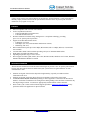
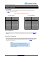
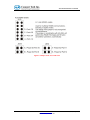
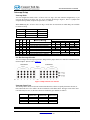
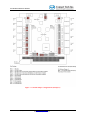
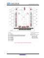
USER MANUAL Xtreme/104 Isolated CTIM-00025 (1.08) – July 2011 Xtreme/104 Isolated User Manual Copyright Notice The information contained in this document is subject to change without notice. Connect Tech Inc. shall not be liable for errors contained herein or for incidental consequential damages in connection with the furnishing, performance, or use of this material. This document contains proprietary information that is protected by copyright. All rights are reserved. No part of this document may be photocopied, reproduced, or translated to another language without the prior written consent of Connect Tech, Inc. Copyright © 2008 by Connect Tech Inc. Trademark Acknowledgement Connect Tech Inc. acknowledges all trademarks, registered trademarks and/or copyrights referred to in this document as the property of their respective owners. Not listing all possible trademarks or copyright acknowledgments does not constitute a lack of acknowledgment to the rightful owners of the trademarks and copyrights mentioned in this document. Revision History Revision 1.08 July 2011 Add additional information regarding IRQ modes, IRQ selections and IRQ Status Port. Revision 1.07 June 2011 Corrected figures Revision 1.06 January 2011 Added Figures Revision 1.05 December 2010 Added Figures Revision 1.04 November 2010 Added Figures Revision 1.03 November 13, 2008 Added Header to Serial Port Mapping Table Converted Revision 1.02 to new manual format Revision 1.02 November 2005 Release CTIM-00025 (1.08) July 2011 www.connecttech.com 800-426-8979 | 519-836-1291 2 Xtreme/104 Isolated User Manual Table of Contents Copyright Notice ............................................................................................................................................... 2 Trademark Acknowledgement ........................................................................................................................ 2 Revision History ................................................................................................................................................ 2 Introduction....................................................................................................................................................... 4 Features ............................................................................................................................................................. 4 Electrical Isolation ............................................................................................................................................ 4 Hardware Installation ...................................................................................................................................... 6 Port Mapping ................................................................................................................................................. 6 Port I/O Addresses ......................................................................................................................................... 6 Status Port I/O Addresses .............................................................................................................................. 6 Custom Port I/O Addresses ............................................................................................................................ 7 Port Control Setup .......................................................................................................................................... 8 Baud Rate Selection ..................................................................................................................................... 10 JG3 Selection Jumper Block ........................................................................................................................ 10 Interrupt Setup ............................................................................................................................................. 11 Software Installation....................................................................................................................................... 12 RS/232/422/485 Interfaces .............................................................................................................................. 12 Electrical Interface Selection ....................................................................................................................... 12 Full Duplex Mode (four wire) ................................................................................................................ 12 Half Duplex RS-422/485 (two wire) ....................................................................................................... 13 Multi-drop Mode (four wire) ................................................................................................................... 13 Line Bias and Termination ...................................................................................................................... 13 Appendix.......................................................................................................................................................... 16 Xtreme/104 Isolated Specifications ............................................................................................................. 16 Operating Environment ........................................................................................................................... 16 PC Bus Interface...................................................................................................................................... 16 Communications...................................................................................................................................... 16 Electrical Isolation................................................................................................................................... 16 Power ...................................................................................................................................................... 16 Connectors/Interface ............................................................................................................................... 16 Dimensions .............................................................................................................................................. 17 Cable Options .......................................................................................................................................... 17 Connectors/Pinouts.................................................................................................................................. 17 Limited Lifetime Warranty ........................................................................................................................... 18 Customer Support Overview ......................................................................................................................... 18 Contact Information ....................................................................................................................................... 18 3 www.connecttech.com 800-426-8979 | 519-836-1291 CTIM-00025 (1.08) July 2011 Xtreme/104 Isolated User Manual Introduction Connect Tech’s Xtreme/104 Isolated adapters are high density, high performance, 12 Port serial adapters that fully comply with PC/104 form factor specifications and offer 1.0 kV AC peak to peak electrical isolation on every signal of every Port. Features ISA bus compatible with 16 bit PC/104 connector Twelve asynchronous I/O Ports o Eight selectable RS-232/422/485 Ports o Four dedicated RS-232 Ports Electrical isolation on each Port using Analog Device’s iCoupler® technology, providing up to 1 kV AC peak to peak of protection Support for all three RS-422/485 modes o Full duplex (four wire) o Half duplex (two wire, with automatic data direction control) o Multi-drop (four wire) Data communication speeds up to 460.8 Kbps (RS-422/485) and 115.2 Kbps (RS-232). Custom baud rates available. 16C2850 dual UARTs control each Port providing 128 bytes of TxD/RxD FIFO buffers Eight jumper selectable I/O address ranges Operating temperature range of -40°C to 85°C Driver support for Linux, QNX, Solaris, SCO Unix, Windows 98/Me, Windows CE/CE .NET, Windows XP/XP Embedded and Windows NT/2000 Electrical Isolation The Xtreme/104 Isolated uses electrical isolator technologies to provide 1.0 kV AC peak to peak isolation between each Port and also between each Port and your system. Please recognize that there are some considerations to note: Isolation can degrade if the board is subjected to high humidity, especially in conditions where condensation can occur. Isolation can degrade if airborne dust is allowed to accumulate on the surface of the board. An electrical shock hazard could exist depending on what equipment is connected to the Xtreme/104 Isolated. Under these circumstances the wiring and/or cabling leading to the Serial Port connections may have high voltages on them. You must use appropriately insulated cables in these situations. Please contact your Connect Tech Technical Support Specialist at [email protected] for any questions related to the application of optical isolation. CTIM-00025 (1.08) July 2011 www.connecttech.com 800-426-8979 | 519-836-1291 4 Xtreme/104 Isolated User Manual Figure 1: Xtreme/104 Isolated Board Diagram 5 www.connecttech.com 800-426-8979 | 519-836-1291 CTIM-00025 (1.08) July 2011 Xtreme/104 Isolated User Manual Hardware Installation Port Mapping Serial Port numbers DO NOT sequentially map to the Xtreme/104 Isolated PCB header numbers. See Table 1 below for Port mapping. Table 1: Serial Port to PCB Header Mapping Sorted by Serial Port Serial Port 1 2 3 4 5 6 7 8 9 10 11 12 Sorted by PCB Header PCB Header P4 P6 P5 P7 P9 P11 P10 P12 P13 P14 P15 P16 PCB Header P4 P5 P6 P7 P9 P10 P11 P12 P13 P14 P15 P16 Serial Port 1 3 2 4 5 7 6 8 9 10 11 12 Port I/O Addresses Port I/O address selections are configured with the jumper block JG3 on the Xtreme/104 Isolated adapter. Use jumpers A, B, and C to select a range of I/O port addresses for the Ports. Please refer to Figure 5 for positions. Status Port I/O Addresses Some operating system device drivers can utilize an Interrupt Status Port, for example Linux. This will improve the performance of Xtreme/104 Isolated. The Xtreme/104 Isolated offers a Status Port and this Port is enabled or disabled using jumper D on jumper block JG3. Please refer to Table 2 for a list of supported Status Port addresses. NOTE: Please make certain that the Status Port Enable jumper is disabled if your application is not using the Status Port. This eliminates the possibility of an address conflict with another device in your system. CTIM-00025 (1.08) July 2011 www.connecttech.com 800-426-8979 | 519-836-1291 6 Xtreme/104 Isolated User Manual Custom Port I/O Addresses If you require specific Port addresses not listed in Table 2 please contact Connect Tech Technical Support at [email protected] for further information. See Figure 5 for Jumper JG3 information. Table 2: Port Address Settings 7 www.connecttech.com 800-426-8979 | 519-836-1291 CTIM-00025 (1.08) July 2011 Xtreme/104 Isolated User Manual Port Control Setup Figure 2: Port Control, Group A (Ports 1 to 4) Figure 3: Port Control, Group B (Ports 5 to 8) CTIM-00025 (1.08) July 2011 www.connecttech.com 800-426-8979 | 519-836-1291 8 Xtreme/104 Isolated User Manual Figure 4: Jumpers JG12, JG13 and JG14 9 www.connecttech.com 800-426-8979 | 519-836-1291 CTIM-00025 (1.08) July 2011 Xtreme/104 Isolated User Manual Baud Rate Selection The Xtreme/104 Isolated is capable of baud rates up to 460.8 Kbps (4X oscillator) or 115.2 Kbps (1X oscillator) depending on whether a jumper block is installed across position JG3-E. (Please refer to Figure 5). JG3 Selection Jumper Block This Jumper block is used for a variety of setup functions. Figure 5: Address and IRQ Setup, JG3 CTIM-00025 (1.08) July 2011 www.connecttech.com 800-426-8979 | 519-836-1291 10 Xtreme/104 Isolated User Manual Interrupt Setup Interrupt Mode You can configure the board so that “All Ports share one IRQ” (the most common configuration), or you can setup the board to use three, four, five or six interrupts. Referring to Figure 5, there is 4 jumpers that setup the Interrupt Mode, Jumpers JG3 positions F, G, H and I. When NOT using the “All Ports share one IRQ” mode, there are restrictions on which IRQ’s are available to each Port Group. Port Group A B C F X Out In Out X X X X Ports 1, 2, 3 and 4 5, 6, 7 and 8 9, 10, 11 and 12 G H I X Out X X In Out X X X Out X X X X In Out Out In In In In In In In IRQ Choices 3, 4, 5 and 6 7, 9, 10, 11 12, 14, 15 Interrupt Mode Ports Interrupting on Row/Group X/A Y/B X/B Y/C X/C ------112 112 112 1,2 3,4 5,6 7,8 9,10 11,12 Jumper G selection Jumper H selection --14 Jumper G selection Jumper H selection 1,2 3,4 Jumper F selection Jumper H selection --58 Jumper F selection Jumper H selection 5,6 7,8 Jumper F selection Jumper G selection --912 Jumper F selection Jumper G selection 9,10 11,12 Y/A All Ports share one IRQ 6 Interrupts (in Port pairs) 3 to 6 Interrupts (Group A selection) 3 to 6 Interrupts (Group A selection) 3 to 6 Interrupts (Group B selection) 3 to 6 Interrupts (Group B selection) 3 to 6 Interrupts (Group C selection) 3 to 6 Interrupts (Group C selection) ISA Bus Interrupt Selection You can configure the interrupt request lines (IRQ) with the jumper blocks JG1 and JG2 on the Xtreme/104 Isolated adapter. (Please refer to Figure 6). Figure 6: IRQ Selection JG1 and JG2 Interrupt Status Ports The Interrupt Status Ports are ISA I/O locations that allow the software to quickly determine the Port (or Ports) that need service. See Table 2 for the I/O addresses of the Status Ports. The upper 4 bits of the value read will always be zero (0), the lower 4 bits are encoded (by port number) as follows. Bit Number 0 1 2 3 11 Port Group A (Status Port A) 1 2 3 4 Port Group B (Status Port B) 5 6 7 8 Port Group C (Status Port C) 9 10 11 12 www.connecttech.com 800-426-8979 | 519-836-1291 CTIM-00025 (1.08) July 2011 Xtreme/104 Isolated User Manual Software Installation Xtreme/104 Isolated adapters are standard multi-port serial adapters that utilize 16C2850 UARTs. In many cases, users have software that will interface directly to the Xtreme/104 Isolated adapters. Many operating systems come with a driver to control access to multiple 8250 style UARTs. Xtreme/104 Isolated adapters currently support device drivers for the following operating systems: ● ● ● ● ● ● ● ● ● ● Linux QNX SCO Unix/Openserver Windows 2000 Windows 98/Me Windows CE Windows CE .NET Windows NT Windows XP Windows XP Embedded The latest manuals, installation guides and drivers are located on the Connect Tech website. Please visit the download zone for more information: http://www.connecttech.com/asp/Support/DownloadZone.asp If you have any questions, please contact Connect Tech Customer Support. Email: [email protected] Phone: 1-800-426-8979 (within North America) Outside North America: 1-519-836-1291 Fax: 1-519-836-4878 RS/232/422/485 Interfaces Electrical Interface Selection The Xtreme/104 Isolated adapter provides jumper selectable RS-232 and RS-422/485 electrical interfaces on eight of its 12 Ports. Position D on jumper blocks J1 through J11 determines the individual electrical interfaces for the Ports. Group “A” Ports are controlled by jumper blocks J4 through J7: J4 for Port 1, J5 for Port 2, J6 for Port 3 and J7 for Port 4. Jumper blocks J8 through J11 determine the electrical interfaces for the “B” group of Ports: J8 for Port 5, J9 for Port 6, J10 for Port 7 and J11 for Port 8. Jumpers installed across position D on any of these jumper blocks enable the RS-232 interface for that Port; otherwise the RS-422/485 interface will apply. (Please refer to Figure 7 and Figure 8 for examples of various electrical interface selections). Full Duplex Mode (four wire) To make sure that there are no jumpers on positions B and C of jumper blocks J4 to J11, you can run the individual RS-422/485 Ports in full duplex mode. In this mode, TxD and RxD are active all the time. This mode is typically used in point-to-point situations much like RS-232. (Please refer to Figure 2 and Figure 3). CTIM-00025 (1.08) July 2011 www.connecttech.com 800-426-8979 | 519-836-1291 12 Xtreme/104 Isolated User Manual Half Duplex RS-422/485 (two wire) By jumpering positions B and C of jumper blocks J4 to J11, along with the corresponding position on JG12, you can run the individual RS-422/485 Ports in half duplex mode. In this mode your Xtreme/104 Isolated adapter controls the transmitter and receiver circuits. RTS is turned on prior to and during transmission to enable the transmit driver and disable the receiver. RTS is turned off when not transmitting to disable the transmit driver (tri-stated) and enable the receiver. The Xtreme/104 Isolated adapter is responsible for timing the RTS toggle. (Please refer to Figure 2 and Figure 3). Multi-drop Mode (four wire) Placing a jumper on position B of jumper blocks J4 to J11 and on the corresponding Auto-enable on JG12, allows you to run the individual RS-422/485 Ports in multi-drop mode. In this mode the TxD line driver is enabled only when data is transmitted and RxD is enabled all the time. (Please refer to Figure 2 and Figure 3). Line Bias and Termination The RS-422/485 Ports of the Xtreme/104 Isolated adapter feature jumper selectable line bias and termination resistors across RxD+/- and jumper selectable 150 termination resistors across TxD+/-. Termination resistors are installed to improve the electrical performance of the RS-485 network. RS-485 networks are always wired in a daisy chain, from point-to-point-to-point and so on. Termination resistors are installed at the most extreme ends of that network; they can not be installed in the middle of the network. No more than two termination resistors can reside in the network. Termination resistors are useful in the following situations: ● ● ● Where long cabling 30m (100ft) or greater is used. Where the cable is of poor quality. When the application is using a high baud rate, 115.2 Kbps or greater. For short point-to-point RS-485 networks, termination resistors are not usually required. While this may reduce power consumption of your adapter, be aware that you may risk poor or intermittent communications without the termination resistors. To install a termination resistor across TxD+/- on your Xtreme/104 Isolated adapter, install the appropriate jumper for a given Serial Port. (Please refer to Figure 2 and Figure 3). Bias and Termination resistors are applied across the RxD+/- pins. The bias resistors provide a valid differential voltage across the RxD+/- pins when there is no voltage applied across the RxD+/- input. The termination resistor has the same uses and the TxD+/- terminator as above. The RxD+/- bias and termination resistors are used whenever your application requires the following: ● ● A terminator resistor across RxD+/The Xtreme/104 Isolated Serial Port is configured as the master in a two wire (Half Duplex) multi-drop network. To install a bias and termination resistor across RxD+/- on your Xtreme/104 Isolated adapter install the appropriate jumpers, a total of two, for a given Serial Port. (Please refer to Figure 2 and Figure 3). 13 www.connecttech.com 800-426-8979 | 519-836-1291 CTIM-00025 (1.08) July 2011 Xtreme/104 Isolated User Manual Figure 7: Common Jumper Configurations (Example 1) CTIM-00025 (1.08) July 2011 www.connecttech.com 800-426-8979 | 519-836-1291 14 Xtreme/104 Isolated User Manual Figure 8: Common Jumper Configurations (Example 2) 15 www.connecttech.com 800-426-8979 | 519-836-1291 CTIM-00025 (1.08) July 2011 Xtreme/104 Isolated User Manual Appendix Xtreme/104 Isolated Specifications Operating Environment Storage: 40ºC to 150ºC (40ºF to 302ºF) Operating: -40ºC to 70ºC (-40ºF to 158ºF) Humidity: 90% relative humidity, non-condensing PC Bus Interface Base address for UARTs is jumper selectable. Each UART requires eight I/O addresses (96 I/O addresses required). Custom baud rates are also available. Please contact [email protected] for more information. Communications UARTs XR16C2850 dual UART communication controllers On chip 128 byte TxD and RxD FIFO buffers per Port Automatic RTS/CTS (Hardware) flow control Automatic XON/XOFF (Software) flow control Compatible with 16550 style software drivers RS-232 Programmable baud rate generator - up to 115.2 Kbps on all dedicated RS-232 Ports 230.4 Kbps on all switchable Ports RS-422/485 Programmable baud rate generator - up to 460.8 Kbps on all RS-422/485 Ports Full duplex (four wire) Half duplex (two wire) Multi-drop (four wire) Jumper selectable Automatic direction control for two-wire half duplex Jumper selectable RxD/TxD line/bias termination resistors Control Signals RS-232: TxD; RxD; RTS; CTS, ISOGND RS-422/485: TxD±; RTS±; CTS±; RxD±, ISOGND Electrical Isolation 1.0 kV AC peak to peak on every signal of every Port Power +5V DC @ 500mA (typical) +5V DC @ 1A (maximum) Connectors/Interface One PC/104 16-bit expansion connector RS-232/422/485: Ten pin right angle 2mm connectors RS-232: Six pin right angle 2mm connectors (Please refer to Figure 9 for pinouts) CTIM-00025 (1.08) July 2011 www.connecttech.com 800-426-8979 | 519-836-1291 16 Xtreme/104 Isolated User Manual Dimensions Xtreme/104 Isolated Main PCB: 10.10cm /3.55” including connectors (W), 9.60cm/3.78” (L) Daughter Board: 5.80cm/2.27” (W), 5.50cm/2.18” (L) Height is fully compliant with PC/104 specification 2.3. Cable Options 304 mm DB-9 male cables Connectors/Pinouts Connect Tech recommends using the following mating connectors for your Xtreme/104 Isolated product: 10 pin: Hirose part number - DF11-10DS-2C, DigiKey part number - H2023-ND 6 pin: Hirose part number - DF11-6DS-2C, DigiKey part number - H2021-ND Crimping sockets: Hirose part number - DF11-2428SCA Individual wire assemblies for the DF11 series can be found in DigiKey’s online catalogue at www.digikey.com. Figure 9: Pinouts 17 www.connecttech.com 800-426-8979 | 519-836-1291 CTIM-00025 (1.08) July 2011 Xtreme/104 Isolated User Manual Limited Lifetime Warranty Connect Tech Inc. provides a Lifetime Warranty for all Connect Tech Inc. products. Should this product, in Connect Tech Inc.'s opinion, fail to be in good working order during the warranty period, Connect Tech Inc. will, at its option, repair or replace this product at no charge, provided that the product has not been subjected to abuse, misuse, accident, disaster or non Connect Tech Inc. authorized modification or repair. You may obtain warranty service by delivering this product to an authorized Connect Tech Inc. business partner or to Connect Tech Inc. along with proof of purchase. Product returned to Connect Tech Inc. must be pre-authorized by Connect Tech Inc. with an RMA (Return Material Authorization) number marked on the outside of the package and sent prepaid, insured and packaged for safe shipment. Connect Tech Inc. will return this product by prepaid shipment service. The Connect Tech Inc. lifetime warranty is defined as the serviceable life of the product. This is defined as the period during which all components are available. Should the product prove to be irreparable, Connect Tech Inc. reserves the right to substitute an equivalent product if available or to retract lifetime warranty if no replacement is available. The above warranty is the only warranty authorized by Connect Tech Inc. Under no circumstances will Connect Tech Inc. be liable in any way for any damages, including any lost profits, lost savings or other incidental or consequential damages arising out of the use of, or inability to use, such product. Customer Support Overview If you experience difficulties after reading the manual and/or using the product, contact the Connect Tech reseller from which you purchased the product. In most cases the reseller can help you with product installation and difficulties. In the event that the reseller is unable to resolve your problem, our highly qualified support staff can assist you. Our online Support Center is available 24 hours a day, seven days a week on our website at: www.connecttech.com/sub/support/support.asp. Please go to the Download Zone or the Knowledge Database for product manuals, installation guides, device driver software and technical tips. Submit your questions to our technical support engineers at [email protected]. Our technical support is always free. Contact Information Telephone/Facsimile Technical Support representatives are ready to answer your call Monday through Friday, from 8:30 a.m. to 5:00 p.m. Eastern Standard Time. Our numbers for calls are: Toll: 800-426-8979 (North America only) | Tel: 519-836-1291 | Fax: 519-836-4878 (online 24 hours) Email/Internet You may contact us through the Internet. Our email and URL addresses are: [email protected] | [email protected] | www.connecttech.com Mail/Courier Connect Tech Inc. 42 Arrow Road Guelph, Ontario, N1K 1S6, Canada CTIM-00025 (1.08) July 2011 www.connecttech.com 800-426-8979 | 519-836-1291 18