1
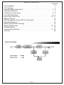
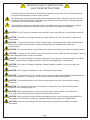
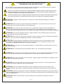
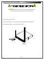
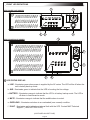
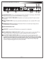
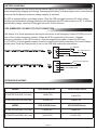
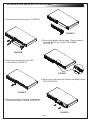
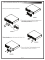
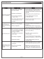
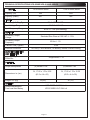
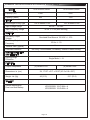
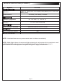
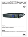
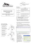
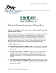
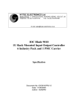
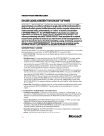
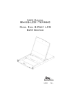
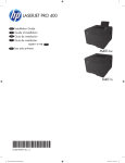
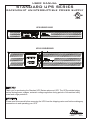
USER MANUAL
STANDARD UPS SERIES
RACKMOUNT UNINTERRUPTIBLE POWER SUPPLY
C
UL
R
US
LISTED
UPS-S500R/S1000R
UPS-S1500R/S2200R
THANK YOU
Thank you for purchasing the Standard UPS Series rackmount UPS. The UPS provides battery
backup during power outages, automatic voltage regulation during periods of inconsistent utility
power and surge protection.
IMPORTANT
Please read this manual before removing the UPS from the shipping carton and before making any
connections to and operating your UPS.
I-00690
Rev E
TABLE OF CONTENTS
Page No.
Circuit Diagram . . . . . . . . . . . . . . . . . . . . . . . . . . . . . . . . . . . . . . . . . . . . . . . . 2
FCC Warning . . . . . . . . . . . . . . . . . . . . . . . . . . . . . . . . . . . . . . . . . . . . . . . . . . 3
Important Safety Instructions . . . . . . . . . . . . . . . . . . . . . . . . . . . . . . . . . . . 4 - 5
Unpacking/Parts List . . . . . . . . . . . . . . . . . . . . . . . . . . . . . . . . . . . . . . . . . . . . . 6
Installation and Mounting. . . . . . . . . . . . . . . . . . . . . . . . . . . . . . . . . . . . . . . . 6 - 7
Front LED Definitions . . . . . . . . . . . . . . . . . . . . . . . . . . . . . . . . . . . . . . . . . . 8 - 9
Rear Panel Feature Set . . . . . . . . . . . . . . . . . . . . . . . . . . . . . . . . . . . . . . 10 - 11
Battery Charging . . . . . . . . . . . . . . . . . . . . . . . . . . . . . . . . . . . . . . . . . . . . . . . 12
EPO (Emergency Power Off) Port Connection . . . . . . . . . . . . . . . . . . . . . . . . 12
Estimated Runtimes . . . . . . . . . . . . . . . . . . . . . . . . . . . . . . . . . . . . . . . . . . . . . 12
Battery Replacement Warnings . . . . . . . . . . . . . . . . . . . . . . . . . . . . . . . . . . . . 13
Battery Replacement . . . . . . . . . . . . . . . . . . . . . . . . . . . . . . . . . . . . . . . . .14 - 15
Troubleshooting . . . . . . . . . . . . . . . . . . . . . . . . . . . . . . . . . . . . . . . . . . . . . . . .16
Technical Specifications . . . . . . . . . . . . . . . . . . . . . . . . . . . . . . . . . . . . . . 17 - 19
Warranty . . . . . . . . . . . . . . . . . . . . . . . . . . . . . . . . . . . . . . . . . . . . . . . . . . . . . . 20
CIRCUIT DIAGRAM
Page 2
FCC WARNING
NOTE: This equipment has been tested and found to comply with the limits for a Class B digital device,
pursuant to Part 15 of the FCC Rules. These limits are designed to provide reasonable protection against
harmful interference in a residential installation. This equipment generates, uses and can radiate radio
frequency energy and, if not installed and used in accordance with the instructions, may cause
harmful interference to radio communications. However, there is no guarantee that interference will not
occur in a particular installation. If this equipment does cause harmful interference to radio or television
reception, which can be determined by turning the equipment off and on, the user is encouraged to try to
correct the interference by one or more of the following measures:
(1) Reorient or relocate the receiving antenna.
(2) Increase the separation between the equipment and receiver.
(3) Connect the equipment into an outlet on a circuit different from that to which the receiver is connected.
(4) Consult the dealer or an experienced radio/TV technician for help.
WARNING: A shielded-type power cord is required in order to meet FCC emission limits and also to
prevent interference to the nearby radio and television reception. It is essential that only the supplied
power cord be used. Use only shielded cables to connect I/O devices to this equipment.
WARNING: Any changes or modifications not expressly approved by the guarantee of this device
could void the user’s authority to operate the equipment.
REMARQUE: Cet appareil a subi des tests de contrôle et a été déclaré conforme aux limites imposées
aux appareils numériques de Classe B par la section 15 de la réglementation FCC. Ces limites ont été
établies pour assurer une protection raisonnable contre les interférences indésirables lorsque l’appareil
fonctionne dans un environnement résidentiel. Cet appareil génère, exploite et peut émettre un
rayonnement de fréquence radio. En outre, en cas d’installation et d’utilisation non conforme aux
instructions, il risque de provoquer des interférences indésirables avec les transmissions radio.
Rien ne garantit qu’aucune interférence ne se produira dans une installation donnée. Si l’utilisation
de cet appareil provoque des interférences indésirables avec la réception radio ou télévision (ce que
vous pouvez déterminer en l’éteignant, puis en le rallumant), il est recommandé d’essayer d’y remédier
en prenant une ou plusieurs des mesures suivantes :
(1) Réorientez ou déplacez l’antenne de réception.
(2) Augmentez la distance entre l’appareil et le récepteur.
(3) Branchez l’appareil sur une prise de courant située sur un circuit différent de celui du récepteur.
(4) Contactez votre détaillant ou un technicien qualifié en réparation radio/télévision. Si un accessoire
spécifique est nécessaire pour assurer la conformité de l’appareil, cela doit être précisé dans les
instructions.
ATTENTION: Un cordon d’alimentation blindé est nécessaire pour respecter les limites d’émission
fixées par la FCC et pour empêcher les interférences avec les récepteurs radio ou télévision placés à
proximité. Il est impératif de n’utiliser que le cordon d’alimentation fourni. Ne connectez de périphériques
d’entrée/sortie à cet appareil qu’avec des câbles blindés.
ATTENTION: Toute modification apportée à ce produit qui n’est pas expressément approuvée par la
garantie peut priver l’utilisateur de son droit d’utiliser l’appareil.
Page 3
IMPORTANT SAFETY INSTRUCTIONS
SAVE THESE INSTRUCTIONS
Please read and follow all instructions carefully during installation and operation of this unit. Read this manual
thoroughly before attempting to unpack, install or operate.
The lightning flash with the arrowhead symbol, within an equilateral triangle is intended to alert the user to the
presence of uninsulated dangerous voltage within the product’s enclosure that may be of sufficient magnitude
to constitute a risk of electric shock to persons.
The exclamation point within an equilateral triangle is intended to alert the user to the presence of important
operating and maintenance (servicing) instructions in the literature accompanying the appliance.
CAUTION: The UPS must be connected to a grounded AC power outlet with fuse or circuit breaker protection.
CAUTION: The battery can energize hazardous live parts inside the unit, even when the AC input power is
disconnected.
CAUTION: To prevent the risk of fire or electric shock, install in a temperature and humidity controlled indoor
area, free of conductive contaminants. (Please see specifications for acceptable temperature and
humidity range).
CAUTION: To avoid electric shock, turn off the unit and unplug it from the AC power before servicing the battery.
CAUTION: To reduce the risk of electric shock, do not remove the cover, except to service the battery. There are
no serviceable parts inside, except for the battery.
CAUTION: Do not use for medical or life support equipment. Do not use in any circumstance that would affect
operation or safety of any life support equipment, with any medical applications, or patient care.
CAUTION: Do not open or mutilate the batteries. Released material is harmful to the skin and eyes and
may be toxic.
CAUTION: Do not dispose of batteries in a fire. The batteries may explode.
CAUTION: To reduce the risk of fire, connect only to a circuit provided with 20 amperes maximum branch
overcurrent protection in accordance with the National Electrical Code, ANSI/NFPA 70.
CAUTION: To avoid electrical shock, turn off the unit and unplug it from the AC power before installing a
component.
CAUTION: Do not plug the machine into an outlet that is not grounded. If you need to de-energize this
equipment, turn off and unplug the unit.
CAUTION: Before replacing batteries, remove conductive jewelry such as chains, wrist watches and
rings. High energy through conductive materials could cause severe burns.
CAUTION: (Only required for unit with HB flame class battery) Not for use in a computer room as defined in
the Standard for the Protection of Electronic Computer/Data Processing Equipment, ANSI/NFPA 75.
CAUTION: Ensure the wall outlet and UPS are located near the equipment being attached for proper
accessibility.
Page 4
CONSIGNES DE SÉCURITÉ IMPORTANTES
CONSERVER CES INSTRUCTIONS
S'il vous plaît lire et suivre attentivement les instructions lors de l'installation et le fonctionnement de cet appareil.
Lisez ce manuel soigneusement avant de déballer, installer ou utiliser.
L'éclair avec le symbole de flèche dans un triangle équilatéral est destiné à alerter l'utilisateur de la présence
d'une tension dangereuse non isolée dans l'enceinte du produit qui peut être d'une ampleur suffisante pour
constituer un risque de choc électrique pour les personnes
Le point d'exclamation dans un triangle équilatéral est destiné à alerter l'utilisateur de la présence d'importants
instructions d’opération et de maintenance (entretien) dans la documentation accompagnant l'appareil
ATTENTION: L’onduleur doit être branché sur une prise de courant alternatif protégée par un fusible ou
un disjoncteur.
ATTENTION: Même lorsque le cordon d’alimentation est débranché, les parties internes peuvent recevoir
suffisamment de courant de la batterie pour être dangereuses.
ATTENTION: Pour éviter les risque d'incendie ou de choc électrique, l’appareil doit être installé dans un
local libre de contaminants conducteurs et dont la température et l’humidité sont contrôlées (reportez-vous
aux spécifications techniques pour pren dre connaissance des plages de température et d’humidité acceptables).
ATTENTION: Pour éviter la décharge électrique, éteignez arrêtez l’unité et débranchez-la de la source de
courant alternatif avant d’entretenir la batterie.
ATTENTION: Pour réduire le risque de choc électrique, ne pas enlever le couvercle, à l'exception de réparer la
batterie. Il n'y a pas de pièces réparables par l'intérieur, sauf pour la batterie.
ATTENTION: Ne pas utiliser pour l'équipement de soutien médical ou de la vie. Ne pas utiliser en toute
circonstance susceptible d'affecter fonctionnement ou la sécurité de tout le matériel de soutien de la vie,
avec toutes les applications médicales ou les soins aux patients.
ATTENTION: N’ouvrez pas ou ne mutilez pas les batteries. Le matériel libéré est nocif à la peau et aux yeux
et peut être toxique.
ATTENTION: Ne vous débarrassez pas des batteries dans un feu. Les batteries peuvent éclater.
ATTENTION: Pour réduire le risque d'incendie, relie seulement à un circuit équipé de 20 ampères de branche
de circuit de protection maximum de surintensité selon le code électrique national, ANSI/NFPA 70.
ATTENTION: Pour éviter les risques de choc électrique, éteignez l’appareil et débranchez l’alimentation avant
d’installer un composant quelconque.
ATTENTION: Ne le branchez pas sur une prise de courant sans mise à la terre. Si vous souhaitez mettre
l’appareil hors tension, éteignez-le avant de le débrancher.
ATTENTION: Avant de remplacer des batteries, enlever conducteur bijoux tels que des chaînes, des
montres-bracelet et des anneaux. La haute énergie par les matériaux conducteurs a pu causer les brûlures
graves.
ATTENTION: (Seulement requis pour l'unité avec HB batterie de classe de la flamme) Ne pas utiliser dans une
salle informatique tel que défini dans la norme pour la protection des équipements informatiques/traitement des
données, ANSI/NFPA 75.
ATTENTION: Assurer la prise murale et UPS sont situés près de l'équipement étant fixé pour bonne
accessibilité.
Page 5
UNPACKING/PARTS LIST
DO NOT LIFT THE UPS WHILE HOLDING THE FRONT FACE OF THE UNIT.
THIS MAY DAMAGE THE UNIT. ALWAYS LIFT THE UPS BY HOLDING IT
BY BOTH SIDES.
LIFT OUT OF BOX
WHILE HOLDING
BOTH SIDES OF
UPS
LIFT OUT OF BOX
WHILE HOLDING
BOTH SIDES OF
UPS
The UPS is very heavy and should be handled by two (2) people. After the product is removed from its
shipping carton, inspect the UPS before installing and operating. The shipping carton should contain the
following items:
(1) UPS unit; (1) User’s Manual; (2) Rack ears; (8) 10-32 Rack ear screws, for 1U models, (12) for 2U
models; (2) Rackmount handles; (installation of handles is optional); (5) 8-32 Rackmount handle screws
(installation of handles is optional); (1) Middle Atlantic Power Manager Software CD, (1) USB Cable,
(1) EPO Cable
MOUNTING/INSTALLATION
NOTE: Installation of handles is optional.
1) If using the provided handles install them now
using provided 8-32 screws. (FIGURE A)
NOTE: The handles cannot be installed
after the unit is rack-mounted.
FIGURE A
2) Install ears as shown using provided 10-32 screws.
(FIGURE B)
RACK EAR
SCREW
FIGURE B
RACK EAR
Page 6
MOUNTING/INSTALLATION CONTINUED
CAUTION: THIS UNIT IS HEAVY, LIFT CAREFULLY
(Two person lift recommended for 2RU models)
ATTENTION: Cette unité est lourde, soulevez avec precaution
(Deux personne soulever recommandé pour 2RU modèles)
2) Determine mounting location.
3) Carefully lift the unit to the mounting position constantly supporting the bottom.
4) Install the front of the unit to the rackrail. (FIGURE C)
RACKSCREWS
(4X)
FIGURE C
Page 7
FRONT LED DEFINITIONS
1
UPS-S500R/S1000R SHOWN
5
2
3
4
1
UPS-S1500R/S2200R SHOWN
2
3
5
4
1 LED STATUS DISPLAY:
a. LINE - Illuminates green when power is supplied by the AC mains. The LED will be off when the
unit is battery back up mode.
b. AVR - Illuminates green to indicate that the UPS is boosting the line voltage.
c. BATTERY - Illuminates orange to indicate that the UPS is in battery backup mode. The LED is
off when in line-interactive mode.
d. MUTE - Illuminates orange to indicate that the audible alarm is muted.
e. OVERLOAD - Illuminates red when in an overloaded (over-current) condition.
f. FAULT - Illuminates red to indicate an internal fault with the UPS. Contact MAP Technical
Support. (1-800-266-7225 x1593)
(CONTINUED ON NEXT PAGE)
Page 8
FRONT FEATURE SET CONTINUED
2
POWER ON/OFF PUSH BUTTON : Press to turn on or off.
3
MUTE PUSH BUTTON: Press and hold for 2 seconds to mute the audible alarm. The ‘Mute’ LED
will illuminate. Press and hold again to enable the audible alarm.
4
BATTERY BAR GRAPH: Indicates the approximate amount of battery capacity remaining in 25%
increments. A fully charged battery will have all four LEDs illuminated green.
5
LOAD BAR GRAPH: Indicates the approximate percentage of load current drawn in 25%
increments. A fully loaded UPS will have all four LEDs illuminated green.
(REAR FEATURES ON NEXT PAGE)
Page 9
UPS-S500R/S1000R REAR FEATURE SET
1
8a
8
7 6
2
3
5
4
1 EXPANSION PORT: Slot for optional Network Interface Card (NIC). Part Number UPS-IPCARD.
Refer to the instructions with the UPS-IPCARD for configuration.
2 AC OUTPUT CIRCUIT BREAKERS: Resettable circuit breakers provides AC output overload
protection.
3 INPUT POWER CORD: Heavy-duty permanently attached power cord, connects UPS to mains
power.
4 WIRING FAULT LED: Red LED that will illuminate if there is mis-wired input voltage such as
an open ground, or reversed polarity.
5 GROUND/BONDING STUD
6 USB PORT: Connects the UPS directly to your computer for configuration.
7 EPO (EMERGENCY POWER OFF) PORT: The EPO port may be used to connect the UPS to a
contact closure switch or control system to enable emergency shutdown (see page 12).
8 AC OUTLETS (BANK CONTROLLED): All AC outlets provide connected equipment with
AC line power, surge protection and line noise filtering during normal operation. Automatic voltage
regulation boosts low voltage without using battery power. All outlets provide battery power during
blackouts and severe brownout or severe high voltage conditions. The non-critical load outlets (8a)
can be configured to automatically shut down during a power outage event providing longer
up-time for equipment plugged into the critical load outlets.
Page 10
UPS-S1500R/S2200R REAR FEATURE SET
1a
2
10
1
4
3
9
8
7
6
5
1 AC OUTLETS (BANK CONTROLLED): All AC outlets provide connected equipment with
AC line power, surge protection and line noise filtering during normal operation. Automatic voltage
regulation boosts low voltage without using battery power. All outlets provide battery power during
blackouts and severe brownout or severe high voltage conditions. The non-critical load outlets (1a)
can be configured to automatically shut down during a power outage event providing longer
up-time for equipment plugged into the critical load outlets.
2 AC OUTPUT CIRCUIT BREAKERS (CRITICAL LOAD BANK): Resettable circuit breakers provides
AC output overload protection.
3 EXPANSION PORT: Slot for optional Network Interface Card (NIC). Part Number UPS-IPCARD.
Refer to the instructions with the UPS-IPCARD for configuration.
4 AC OUTPUT CIRCUIT BREAKERS (ALL OUTLETS): Resettable circuit breakers provides
AC output overload protection.
5 WIRING FAULT LED: Red LED that will illuminate if there is mis-wired input voltage such as
an open ground, or reversed polarity.
6 INPUT POWER CORD: Heavy-duty permanently attached power cord, connects UPS to mains
power.
7 EPO (EMERGENCY POWER OFF) PORT: The EPO port may be used to connect the UPS to a
contact closure switch or control system to enable emergency shutdown (see page 12).
8 USB PORT: Connects the UPS directly to your computer for configuration.
9 AC OUTPUT CIRCUIT BREAKERS (NON-CRITICAL LOAD BANK): Resettable circuit breakers
provides AC output overload protection.
10 GROUNDING/BONDING STUD
Page 11
BATTERY CHARGING
The UPS is shipped from the factory with its internal battery fully charged. However, the battery may lose
some charge during shipping and storage. Recharging the battery for at least eight hours is recommended
to ensure that the battery's maximum charge capacity is achieved.
The UPS is equipped with an auto-charge feature. When the UPS is plugged into mains AC supply voltage,
the battery will automatically recharge (the battery will charge with the UPS either turned on or off). To maintain
optimal battery charge, leave the UPS plugged into an AC outlet at all times.
EPO (EMERGENCY POWER OFF) PORT CONNECTION
This feature is for those applications that require connection to an Emergency Power Off (EPO) circuit in
case of fire or other emergency situation. When the UPS is connected to this circuit, it enables
emergency shutdown of the UPS’s inverter. Using the supplied gray cable, connect the EPO port
of your UPS to a user-supplied normally closed or normally open switch according to the circuit diagram
shown below. Press the Power switch to turn on the UPS after making the connections.
OPTION 1: USER SUPPLIED NORMALLY CLOSED SWITCH
RJ11
PLUG
4
3
2
3-4 JUMPER
N.C. EPO SWITCH
1
NO CONNECTION
OPTION 2: USER SUPPLIED NORMALLY OPEN SWITCH
RJ11
PLUG
4
3
2
1
N.O. EPO SWITCH
NO CONNECTION
ESTIMATED RUNTIMES
MODEL
UPS-S500R Series
UPS-S1000R Series
ESTIMATED RUNTIME (Full Load)
3 MINUTES
3 MINUTES
ESTIMATED RUNTIME (Half Load)
12 MINUTES
13 MINUTES
MODEL
UPS-S1500R Series
UPS-S2200R Series
ESTIMATED RUNTIME (Full Load)
6 MINUTES
4 MINUTES
ESTIMATED RUNTIME (Half Load)
18 MINUTES
13 MINUTES
Page 12
BATTERY REPLACEMENT WARNINGS
CAUTION: RISK OF EXPLOSION IF BATTERY IS REPLACED BY AN INCORRECT TYPE.
CAUTION: Risk of Energy Hazard, 24 V, maximum 18 Ampere-hour batteries. Before replacing batteries, remove
conductive jewelry such as chains, wrist watches, and rings. High energy through conductive materials could
cause severe burns (UPS-S1500R/UPS-S2200R).
CAUTION: Risk of Energy Hazard, 24 V, maximum 16 Ampere-hour batteries. Before replacing batteries, remove
conductive jewelry such as chains, wrist watches, and rings. High energy through conductive materials could
cause severe burns (UPS-S500R/UPS-S1000R).
NOTE: Please contact your local government for battery disposal practices in your area, or refer to the label
on the battery.
AVERTISSEMENTS DE REMPLACEMENT DE BATTERIE
ATTENTION: RISQUE D'EXPLOSION SI LA BATTERIE DE REMPLACEMENT PAR UN TYPE INCORRECT.
ATTENTION: Risques d'énergie danger, 24 V, maximaux 18 ampère-heure batterie. Avant de remplacer des
batteries, enlever conducteur bijoux tels que des chaînes, des montres-bracelet et des anneaux. La haute énergie
par les matériaux conducteurs a pu causer les brûlures graves (UPS-S1500R/UPS-S2200R).
ATTENTION: Risques d'énergie danger, 24 V, maximaux 16 ampère-heure batterie. Avant de remplacer des
batteries, enlever conducteur bijoux tels que des chaînes, des montres-bracelet et des anneaux. La haute énergie
par les matériaux conducteurs a pu causer les brûlures graves (UPS-S500R/UPS-S1000R).
REMARQUE: S'il vous plaît contactez votre administration locale pour les pratiques d'élimination de la batterie de
votre région, ou se référer à l'étiquette sur la batterie.
Page 13
UPS-S500R/S1000R SERIES BATTERY REPLACEMENT
1) Gently remove the front panel. (FIGURE D)
FIGURE D
2) Remove the battery access panel. Three screws for
the UPS-S500R, two for the UPS-S1000R.
(FIGURE E)
FIGURE E
3) Disconnect the wires from the UPS
to the battery. (FIGURE F)
FIGURE F
4) Remove the one screw that secures the battery to the
UPS. (FIGURE G)
FIGURE G
5) Remove the battery. Replace by performing
the previous steps in reverse. (FIGURE H)
FIGURE H
Page 14
UPS-S1500R/S2200R SERIES BATTERY REPLACEMENT
1) Gently remove the front panel. (FIGURE I)
FIGURE I
2) Remove the two screws affixing the battery access
panel. Disconnect the wires from the UPS
to the battery. (FIGURE J)
FIGURE J
3) Remove the four screws that secures the battery to the
UPS. (FIGURE K)
FIGURE K
4) Remove the battery. Replace by performing the
previous steps in reverse. (FIGURE L)
FIGURE L
Page 15
TROUBLESHOOTING
Problem
Solution
Possible Cause
1. Circuit breaker has tripped
due to an overload.
2. Batteries are discharged
Outlets do not provide
power to equipment. 3. Unit has been damaged by
a surge or spike.
1. Turn the UPS off and unplug at least one
piece of equipment. Wait 10 seconds,
reset the circuit breaker, and then turn on
the UPS.
2. Recharge the unit for at least 8 hours.
3. Contact Middle Atlantic Products
at 1-800-266-7225.
4. Non critical outlets have turned 4. Push the bottom Reset button to turn on
the Non critical outlets.
off automatically due to an
overload.
1. Battery is not fully charged.
The UPS does not
perform the expected
2. Battery is degraded.
runtime.
The UPS will not turn
on.
1. Recharge the battery by leaving the UPS
plugged in.
2. Contact Middle Atlantic Products about
replacement batteries at 1-800-266-7225.
1. The on/off switch is designed
to prevent damage by rapidly
turning it on and off.
1. Turn the UPS off. Wait 10 seconds and
then turn the UPS on.
2. The UPS is not connected to
an AC outlet.
2. The UPS must be connected to a
110/120V outlet.
3. The battery is degraded.
3. Contact Middle Atlantic Products about
replacement batteries at 1-800-266-7225.
4. Mechanical problem.
4. Contact Middle Atlantic Products at
1-800-266-7225.
1. The cable is connected to the
wrong port.
1. Connect the cable to the UPS. You must
use the cable that came with the UPS.
Middle Atlantic Power
Manager software is 2. The unit is not providing
battery power.
inactive
Page 16
2. Shutdown your computer and turn the
UPS off. Wait 10 seconds and turn the
UPS back on. This should reset the unit.
TECHNICAL SPECIFICATIONS UPS-S500R/UPS-S1000R SERIES
MODEL
UPS-S500R Series
UPS-S1000R Series
Capacity (VA)
500
1000
Capacity (Watts)
300
600
INPUT
Cord Length & Plug Type
10ft. & NEMA 5-15P
Input Voltage Range
Input Frequency Range
90 VAC - 140 VAC
60 Hz +/- 3 Hz (auto sensing)
OUTPUT
On Battery Output
Voltage
Simulated Sine Wave at 120 VAC +/- 10%
On Battery Output
Frequency
60 Hz +/- 1%
8 ms
Transfer Time (Typical)
Overload Protection
On Utility: Circuit Breaker, On Battery: Internal Current Limiting
SURGE PROTECTION
AND FILTERING
Lighting/Surge
Protection
Single Mode, L - N
PHYSICAL
Output Receptacles
Dimensions: in. (cm)
Weight: Lb. (Kg)
(6) NEMA 5-15R
1U, 17.05 x 1.75 x 9.05
(43.3 x 4.4 x 23)
(6) NEMA 5-15R
1U, 17.05 x 1.75 x 15.35
(43.3 x 4.4 x 39)
18 (8.2)
BATTERY
Sealed Maintenance
Free Lead Acid Battery
UPS-S500R: 6V/7.0AH x 2
UPS-S1000R: 6V/7.0AH x 4
Page 17
32 (15)
TECHNICAL SPECIFICATIONS UPS-S1500R/UPS-S2200R SERIES
MODEL
Capacity (VA)
Capacity (Watts)
UPS-S1500R Series
UPS-S2200R Series
1500
2000
900
1320
INPUT
Cord Length & Plug Type
10ft. & NEMA 5-15P
Input Voltage Range
Input Frequency Range
10ft. & NEMA 5-20P
90 VAC - 140 VAC
60 Hz +/- 3 Hz (auto sensing)
OUTPUT
On Battery Output
Voltage
Simulated Sine Wave at 120 VAC +/- 10%
On Battery Output
Frequency
60 Hz +/- 1%
8 ms
Transfer Time (Typical)
Overload Protection
On Utility: Circuit Breaker, On Battery: Internal Current Limiting
SURGE PROTECTION
AND FILTERING
Lighting/Surge
Protection
Single Mode, L - N
PHYSICAL
Output Receptacles
(8) NEMA 5-15R
(8) NEMA 5-20R
Dimensions: in. (cm)
2U, 17.05'' x 3.5'' x 15.25'' (43.3 x 8.8 x 38.7)
Weight: Lb. (Kg)
48 (21.9)
52.7 (23.9)
BATTERY
Sealed Maintenance
Free Lead Acid Battery
UPS-S1500R: 12V/7.0AH x 4
UPS-S2200R: 12V/9.0AH x 4
Page 18
TECHNICAL SPECIFICATIONS (ALL MODELS)
MODELS
Warning Diagnostics
Indicators
Audible Alarms
All Models
Power On, Wiring Fault, LED Display (Using Battery, AVR, Load Level,
Battery Level)
On Battery, Low Battery, Overload
Environmental
Operating Temperature
Operating Relative
Humidity
Communication
Power Manager™ Software
32º F to 104º F (0º C to 40º C)
0 to 95% Non-Condensing
Windows 98/ME/NT/2000/XP/Vista/7
Management
Auto-Charger/Auto-Restart
Yes
Built-in USB Interface
Yes
NOTE: A simulated sine wave may cause certain loads to behave inconsistently.
NOTE: Middle Atlantic does not recommend that equipment with active power factor correction be used
with Standard UPS products due to incompatibility issues. Please refer to the user manual or
specification sheet of the equipment being used verify power supply characteristics.
Page 19
WARRANTY
WARRANTY
Middle Atlantic Products, Inc. (the "Company") warrants the UPS Series Uninterruptible Power Supply product to be free from defects in material or
workmanship under normal use and conditions for a period of (3) three years from date of shipment by the Company, with the following exception: the internal battery is covered for
(2) two years.
The Company's entire liability to the purchaser, and the purchaser's (or any other party's) sole and exclusive remedy, under this warranty shall be limited, at the Company's option, to
either (a) return of and refund of the price paid for, or (b) repair or replacement at the Company's factory of the products purchased, or any part or parts thereof, which the Company
has determined to be defective after inspection thereof at the Company's factory. This warranty does not cover damage due to acts of God, accident, misuse, abuse or negligence by
parties other than the Company, or any modification or alteration of the products. In addition, this warranty does not cover damage due to improper handling, assembly, installation or
maintenance.
THIS WARRANTY IS IN LIEU OF ALL OTHER WARRANTIES OF ANY KIND, EITHER EXPRESSED OR IMPLIED, INCLUDING, BUT NOT LIMITED TO, IMPLIED WARRANTIES
OF MERCHANTABILITY AND FITNESS FOR A PARTICULAR PURPOSE.
TO THE MAXIMUM EXTENT PERMITTED BY APPLICABLE LAW, IN NO EVENT SHALL THE COMPANY BE LIABLE FOR ANY SPECIAL, INCIDENTAL, INDIRECT, OR
CONSEQUENTIAL DAMAGES WHATSOEVER (INCLUDING, WITHOUT LIMITATION, DAMAGES FOR LOSS OF BUSINESS PROFITS, BUSINESS INTERRUPTION OR ANY
OTHER PECUNIARY LOSS) ARISING OUT OF THE USE OF THE PRODUCTS PURCHASED, EVEN IF THE COMPANY HAS BEEN ADVISED OF THE POSSIBILITY OF SUCH
DAMAGES. THE COMPANY'S LIABILITY TO THE PURCHASER (OR ANY OTHER PARTY) HEREUNDER, IF ANY, SHALL IN NO EVENT EXCEED THE PURCHASE PRICE OF
THE PRODUCTS PAID TO THE COMPANY.
Middle Atlantic Products
Voice 973-839-1011 - Fax 973-839-1976 / International Voice +1 973-839-8821 - Fax +1 973-839-4982
middleatlantic.com - [email protected]
Middle Atlantic Canada
Voice 613-836-2501 - Fax 613-836-2690 / middleatlantic.ca - [email protected]
Factory Distribution
USA: NJ - CA - IL Canada: ON - BC
At Middle Atlantic Products we are always listening. Your comments are welcome.
WARRANTY REGISTRATION
IMPORTANT NOTE
Please register your purchase.
http://www2.middleatlantic.com/ups/warranty/registration.aspx
Page 20