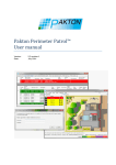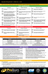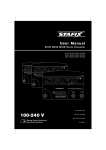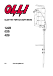
1
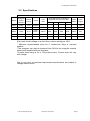
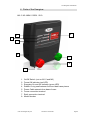
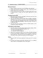
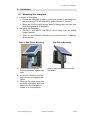
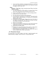
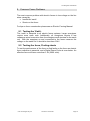
JVA Electric Fence Energiser Installation and Users Manual (M1.5, M3, MB4.5, RSG1, SV2) JVA Energiser User Manual Congratulations on your choice of a JVA Energiser. In choosing to purchase the JVA brand you have opted for the highest quality in electric fencing. Please read this manual entirely before installing your new energiser. All JVA products offer a two-year warranty against faulty components and workmanship but excludes Acts of God, i.e. lightning, flood damage, etc. or malicious damage to the unit or faulty application. To insure your eligibility for this warranty program, please retain your proof of purchase. DANGER! Risk of Shock! High voltages exist inside the electric fence energiser and on the fence terminals. JVA Technologies Pty Ltd 9/17/2013 1:54:00 PM Page 2 JVA Energiser User Manual 1 Table of Contents 1 TABLE OF CONTENTS .................................................................... 3 2 IMPORTANT NOTES – PLEASE READ ........................................... 5 3 4 5 6 7 8 2.1 Electric Fences ................................................................................... 5 2.2 Energisers .......................................................................................... 5 2.3 Power Supply Options ........................................................................ 5 JVA MODELS AND FEATURES....................................................... 6 3.1 Features ............................................................................................. 6 3.2 Specifications ..................................................................................... 7 PARTS OF THE ENERGISER .......................................................... 8 4.1 Fence Connectors .............................................................................. 9 4.2 Energiser LED Display ....................................................................... 9 INSTALLATION............................................................................... 10 5.1 Mounting the energiser ..................................................................... 11 5.2 Connecting to the fence.................................................................... 12 OPERATION ................................................................................... 13 6.1 Electric fences .................................................................................. 13 6.2 Benefits of electric fences ................................................................. 13 COMMON ENERGISER PROBLEMS ............................................. 14 7.1 Moisture and Ants ............................................................................ 14 7.2 Lightning .......................................................................................... 14 7.3 Flat Batteries (Battery units only) ...................................................... 14 COMMON FENCE PROBLEMS ...................................................... 16 8.1 Testing the ‘Ground’. ........................................................................ 16 8.2 Testing the fence, Finding shorts ...................................................... 16 JVA Technologies Pty Ltd 9/17/2013 1:54:00 PM Page 3 JVA Energiser User Manual 9 INSTRUCTIONS FOR INSTALLATION AND CONNECTION OF ELECTRIC FENCES IN AUSTRALIA AS REQUIRED UNDER AS60335.2.26 ......................................................................................... 17 9.1 Definitions ........................................................................................ 17 9.2 General requirements for electric fences .......................................... 17 9.3 Particular requirements for electric animal fences in Australia .......... 19 9.3.1 10 Prohibited mounting ......................................................................... 19 WARRANTY ................................................................................ 20 10.1 For Assistance ................................................................................. 20 10.2 Service or Repairs ............................................................................ 20 JVA Technologies Pty Ltd 9/17/2013 1:54:00 PM Page 4 JVA Energiser User Manual 2 Important notes – PLEASE READ 2.1 Electric Fences 1. Electric fences are not toys; do not let children play with them. 2. Electric fences should only be installed with regard to the relevant Standards and work place health and safety requirements. 3. Electric fences must have a ‘earth’. An electric fence ground is one or more pieces of metal (eg. 1.8m Galvanized earth rods) driven into the earth. 2.2 Energisers 1. The energiser places a very short, very high voltage pulse on the fence live wires approximately once every second. The fence is ‘safe’ in that the pulse is too short to cause electrocution. Please be advised that there is always a risk associated with any device designed to impart an electric shock. Do not allow children or elderly persons to touch the energiser or fence live wires. 2. The maximum length of fence able to be energised depends on many factors, for example the earth resistance, number and spacing of wires on the fence, type/quality of insulators, resistance of wire etc. The amount of grass or shrubbery touching the wires also alters the performance. Fence circuit layout is very important. Another factor to consider is acceptable fence voltage, for some stock situations this is 3kV others require more or less. Therefore the rated mileage of fence that the energiser will power effectively is a guide only. 3. DANGER! The Energiser should never be operated with the cover removed as high voltages exist inside the enclosure while operating. High voltage may remain on some internal parts long after the unit has been switched off. 2.3 Power Supply Options The JVA MB4.5 series of electric fence energisers can be powered from a range of power sources. 12V Battery 24V Battery 12V Battery with Solar panel 240Vac (Via Power Pack) The JVA M1.5, M3, RSG1 and SV2 energisers have limited power supply options. For more information please refer to section 3.2. Important Note: Always ensure adequate ventilation is given to the battery. Lead Acid batteries may emit explosive gases while charging! JVA Technologies Pty Ltd 9/17/2013 1:54:00 PM Page 5 JVA Energiser User Manual 3 JVA Models and Features 3.1 Features Models Mains M1.5, M3 Mains/Battery MB4.5 Battery RSG1 Solar SV2 JVA Technologies Pty Ltd Features Digital control “Smooth” wave shape Fence OK indicator Ant & moisture protection Lightning protection AC surge protection Fused Plug Large Knobs Power on demand Battery protection Solar capability Digital control “Smooth” wave shape Fence OK indicator Ant and moisture protection Lightning protection Power on demand Internal Rechargeable Battery 7 day battery life Ant and moisture protection Recharge from your car or mains power Portable Large Knobs Energiser OK LED Integrated Solar panel and battery Angled Mounting Bracket Low battery indication Digital control “Smooth” wave shape Ant & moisture protection Lightning protection Power on demand 9/17/2013 1:54:00 PM Page 6 JVA Energiser User Manual 3.2 Specifications Specifications Energizer output voltage # Stored Energy Power M1.5 8.0kV 1.6J 230Vac M3 8.0kV 3.3J MB4.5 8.6kV RSG1 SV2 Model ~12V drain *Solar Panel Size for Minimum Expected Sun Hours Per Day *Solar Battery Peak Output 3hrs 4hrs 5hrs >6hrs - - - - - - 1.5J 230Vac - - - - - - 3.0J 6.3J 12 to 24Vdc ^ 530mA 85W 60W 40W 40W 130Ah 4.5J 9.2kV 0.1J 12Vdc 14mA 2W 2W 2W 2W - 0.08 6.4kV 0.14J solar - - - - - - 0.1J # No load, actual voltage on a short fence can be as high as 10kV * Minimum recommended sizes for 5 consecutive days of overcast weather. ^The energiser can also be powered from 240Vac by using the external power pack supplied with the energiser. ~Current drain rating is for a 12V power source. Current drain will vary with voltage. Due to our policy of continual improvement specifications are subject to change without notice. JVA Technologies Pty Ltd 9/17/2013 1:54:00 PM Page 7 JVA Energiser User Manual 4 Parts of the Energiser (M1.5, M3, MB4.5, RSG1, SV2) 8 1 2 3 4 7 6 5 1. 2. 3. 4. 5. 6. 7. 8. On/Off Switch (not on M1.5 and M3) Fence OK indicator (red LED) Energiser On and OK indicator (green LED) Rubber O-ring seal between front and back case pieces Power Cable extends from base of case Fence connection terminal Earth connection terminal Model Number JVA Technologies Pty Ltd 9/17/2013 1:54:00 PM Page 8 JVA Energiser User Manual 4.1 Fence Connectors Earth Fence terminal terminal Fence Connections 1. The earth terminal should be connected to a suitable electric fence earth rod. 2. The “Fence” terminal should be connected to the live wires of the fence. 4.2 Energiser LED Display This feature is included on all units. Fence OK LED Energiser OK LED LED display 1. Fence OK red LED – Flashes if fence voltage is good. If it goes out there is a problem on the fence. (Note: SV2 does not have a Fence OK LED) 2. Energiser OK green LED – Flashes with each pulse to show the unit is on and operating correctly. JVA Technologies Pty Ltd 9/17/2013 1:54:00 PM Page 9 JVA Energiser User Manual 5 Important notes – PLEASE READ Electric Fences 1. Electric fences are not toys; do not let children play with them. 2. Electric fence should be signed: every 10m in areas with public access, every 1 km in rural areas. 3. Electric fences must have an earth. An electric fence earth is one or more piece/s of metal (eg. Star picket) hammered into the ground. Sunlight for the SV2 1. Mount the SV2 so that the solar panel is facing the noon sun (due north and angled at 45 degrees). 2. The SV2 solar panel needs as much direct sunlight as possible, preferably full sun all day. The SV2 is a solar powered energiser and, unlike small solar powered items such as calculators, solar energisers need direct sunlight to generate enough electricity to charge the battery. 3. The solar panel also needs to be clean to operate properly, clean off dust etc. using a damp cloth. SV2 battery and storage 1. The SV2 contains a rechargeable sealed lead acid battery (SLA). SLA battery life is shortened considerably if it is a) left in a discharged state or b) exposed to high temperatures. 2. When not in use store the SV2 in such a way as to allow the panel to get as much light as possible, say on a window sill with the panel facing out. Take the SV2 out into sunlight for a few hours once every month to keep the battery from self discharging. Other 1. Keep the SV2 from being immersed in water and out of extreme heat. 2. Be aware that thieves target solar powered items, so a padlock may be useful in securing the SV2 to a fence post. JVA Technologies Pty Ltd 9/17/2013 1:54:00 PM Page 10 JVA Energiser User Manual 6 Installation 6.1 Mounting the energiser 1. Location of Energiser: Ensure the energiser is kept in a dry environment if operating from mains power (M1.5, M3 and M4.5), either indoors or covered. Mount the SV2 so that the solar panel is facing the noon sun (due north and angled at 45 degrees). 2. Mounting the Energiser The M1.5, M3, MB4.5 and RSG1 can be hung from the plastic hanger bracket. There are two different methods for mounting the SV2. These are shown below. Post or Star Picket Mounting 1. Position the Energiser’s Mounting Bracket against the post. 2. Insert the U-Bolts around the post and into the appropriate holes. 3. Slide the flat metal piece over the bolts and tighten with nuts. Make sure the energiser is stable in its fixed position. JVA Technologies Pty Ltd Star Picket Mounting Simply slide the bracket over the star picket. 9/17/2013 1:54:00 PM Page 11 JVA Energiser User Manual 6.2 Connecting to the fence 1. The electric fence requires a ‘earth’. Drive a galvanized earth rod into the earth. Attach a wire from the Green Earth Connector on the front of the energiser to the earth stake. 2. Connect a wire from the Red Fence Connector on the front of the energiser to the live wire of the fence. 3. Powering the Energiser: Mains Power Source (M1.5, M3 & MB4.5): Plug the mains power cable (M1.5 and M3) or the power adapter (MB4.5) supplied with the energizer into an AC power source and the energiser. Turn the energiser ON at the On/Off switch. Battery Power Source (MB4.5 & RSG1): Attach the battery, red to positive and black to negative battery terminals. For battery choice see specification table 3.2. Turn the energiser ON at the On/Off switch. Solar Power Source (MB4.5): It is recommended that a solar regulator is used in conjunction with a solar panel and a rechargeable battery (For battery choice see specification table 3.2). Please refer to instructions provided with the solar regulator for information regarding its setup. Once the solar regulator, solar panel and rechargeable battery have been configured, connect the energiser to the rechargeable battery. Red to positive and black to negative battery terminals. Turn the energiser ON at the On/Off switch. JVA Technologies Pty Ltd 9/17/2013 1:54:00 PM Page 12 JVA Energiser User Manual 7 Operation 7.1 Electric fences Electric fence energisers work by placing a short, high voltage pulse on fence wires. Although the voltage is very high (up to 10,000V) the pulse is too short to cause electrocution. The result is a zap similar to a static electricity shock from a car seat. The high voltage comes from the Fence terminal of the energiser and is connected to the fence wire or electric fence tape to make a “live” or “hot” wire. Live wires must be insulated (eg. with insulators) from earth or any conductive material touching earth (eg. fence posts). The other connection on the energiser is the ‘earth’ (or ground). Electric fences need ‘earthing’ to complete the circuit: When anything touches the live wire current will flow from the live wire, through the animal to earth back to the ‘earth’ rod and into the energiser earth terminal. You should not feel a shock from the earth connection or earth rod. If you do, the ‘earth’ is probably not sufficient. An electric fence ‘earth’ is some metal in contact with the soil. The more metal in the earth the better, the more moist the soil the better. The larger the energiser and the longer the fence the more ‘earth’ is required. For best results place the energiser in the middle of long lines of fence. A cartwheel pattern of farm fences with the energiser positioned centrally is more effective than a tree arrangement with the energiser at the base of the trunk with many branches. The fence and the ‘earth’ can be measured with an electric fence Digital Voltmeter or Digital Power Probe. 7.2 Benefits of electric fences An electric fence offers a psychological barrier as well as a physical barrier. The risk of injury to livestock is lower than with barbed wire fences. Electric fences cost less to install and maintain than conventional fencing. Users enjoy low maintenance costs because their stock stays off the fence. Their use is versatile - they can be permanent or portable systems, - they can be arranged in variety of designs to suit needs - they are quick and easy to erect They improve pasture and grazing control. JVA Technologies Pty Ltd 9/17/2013 1:54:00 PM Page 13 JVA Energiser User Manual 8 Common Energiser Problems The most common problems with electric fence energisers are: Moisture and Ants Lightning Blown Fuses (AC units only) Flat batteries 8.1 Moisture and Ants Moisture and Ants should not be a significant problem for the JVA range of energisers as they come in a weatherproof case. Still, where possible, keep the energizer protected from the weather. 8.2 Lightning The JVA range of energizers is covered with a two-year warranty that excludes Lightning. Surge protection components inside the energiser are fitted to reduce the risk of damage by lightning. However, nature is capable of performing more extremely than we can test for in the laboratory so, to ensure the wellbeing of your JVA investment for the longer term, it is recommended that a Lightning Protection Kit is installed to prevent lightning damage and possible costly repairs. 8.3 Flat Batteries (Battery units only) The JVA series energisers require a battery that is in good condition to run correctly. The energiser will protect the battery by slowing down and eventually stopping altogether as the battery charge is depleted. For best results check on the energiser at regular intervals. If you are not getting the expected life from the battery consider having it checked by an auto electrician. 8.4 Changing the Battery (Battery units only) Before you start: See “Important Notes”. If the SV2 stops as soon as the sun sets (and it has been getting 8 hours or more sun a day) or if the RSG1 battery charge does not last more than 5 days (a good battery will last 7 days and needs 18 hours to charge), the battery may need replacing. The battery is a sealed, lead acid, 6V, 4.2ah battery. Open the unit and read the battery ah and part number before ordering a new one. These may be available from the manufacturer or through the store where the SV2 or RSG1 was purchased. This type of battery is also readily available through general electronics stores and hardware stores. Notes: The battery must be a rechargeable sealed lead acid battery, never use non rechargeable batteries. The battery should last up to 5 years depending on average temperature and usage. Are you sure it needs replacing? Lead acid batteries should be recycled, not sent to land fill. Send it back to the manufacturer if unsure. JVA Technologies Pty Ltd 9/17/2013 1:54:00 PM Page 14 JVA Energiser User Manual If you don’t feel confident in changing the battery, or can’t find the correct replacement please call us, for a small fee we will be happy to service your unit. Steps Attention: Take Care: Risk of electrical shock! Risk of fire (See “Important Notes”) 1. Turn the SV2/RSG1 off. Be careful not to press firmly on the front of the case as this can sometimes turn the unit on. 2. Place the SV2/RSG1 face down on a clean working surface. 3. Unscrew the six main case crews. 4. Turn the unit over so that its face is facing up. 5. Pry the front off, note there is an O’ring seal. The seal may be stuck to either or both surfaces. If it comes out of the groove simply press it back in. 6. Disconnect the battery leads. Always disconnect the leads at the battery terminals NOT the PCB. Do not allow the wires from battery terminals to touch each other. 7. Remove the old battery. 8. Place the new battery in and secure it in the same way as the original was secured. Do not short the battery terminals. 9. Reconnect the battery leads. 10. Replace the cover ensuring the O’ring seal is in the groove and cables are NOT pinched between the lid and case. 11. While holding the unit together firmly, turn it back over onto its face and replace the six main case screws. 8.5 Dirty Solar Panels The solar panel on the SV2 needs to be clean to operate properly and keep the battery charged. Clean off dust etc. using a damp cloth. JVA Technologies Pty Ltd 9/17/2013 1:54:00 PM Page 15 JVA Energiser User Manual 9 Common Fence Problems The most common problem with electric fences is low voltage on the live wires caused by Insufficient ‘earth’ Shorts on the fence For tips on fence construction please see an Electric Fencing Manual. 9.1 Testing the ‘Earth’. The ‘earth’ is essential to all electric fence systems. Larger energisers require more earth rods. Additionally, all energisers require a low resistance wired connection from the energiser earth terminal to the earth rod. With the energiser on and connected to the fence measure the voltage on the earth rod. It should be less than 0.5kV. 9.2 Testing the fence, Finding shorts To test the performance of the fence or find faults on the fence an electric fence voltmeter is essential, and a Digital Power Probe is even better. An effective fence will have more than 2 kV (2000 volts). JVA Technologies Pty Ltd 9/17/2013 1:54:00 PM Page 16 JVA Energiser User Manual 10 Instructions for installation and connection of electric fences in Australia as required under AS60335.2.26 10.1 Definitions Connecting lead an electric conductor, used to connect the energiser to the electric fence or the earth electrode Electric animal fence an electric fence used to contain animals within or exclude animals from a particular area Electric fence a barrier which includes one or more electric conductors, insulated from earth, to which electric pulses are applied by an energiser 10.2 General requirements for electric fences 4. Electric animal fences shall be installed and operated so that they cause no electrical hazard to persons, animals or their surroundings. 5. Electric animal fence constructions which are likely to lead to the entanglement of animals or persons shall be avoided. 6. An electric animal fence shall not be supplied from two different energisers or from independent fence circuits of the same energiser. For any two separate electric animal fences, each supplied from a separate energiser independently timed, the distance between the wires of the two electric animal fences shall be at least 2 m. If this gap is to be closed, this shall be effected by means of electrically nonconductive material or an isolated metal barrier. 7. Barbed wire or razor wire shall not be electrified by an energiser. 8. Any part of an electric animal fence that is installed along a public road or pathway shall be identified at frequent intervals by warning signs securely fastened to the fence posts or firmly clamped to the fence wires. 1. The size of the warning sign shall be at least 100 mm x 200 mm. 2. The background colour of both sides of the warning sign shall be yellow. The inscription on the sign shall be black and shall be either: 1. the symbol of Figure 1, or 2. the substance of TAKE CARE – ELECTRIC ANIMAL FENCE. 3. The inscription shall be indelible, inscribed on both sides of the warning sign and have a height of at least 25 mm. JVA Technologies Pty Ltd 9/17/2013 1:54:00 PM Page 17 JVA Energiser User Manual Figure 1 – Warning plate symbol 9. The energiser earth electrode shall penetrate the ground to a depth of at least 1 m. 10. Connecting leads that are run inside buildings shall be effectively insulated from the earthed structural parts of the building. This may be achieved by using insulated high voltage cable. 11. Connecting leads that are run underground shall be run in a conduit of insulating material or else insulated high voltage cable shall be used. Care must be taken to avoid damage to the connecting leads due to the effects of animal hooves or tractor wheels sinking into the ground. 12. Connecting leads shall not be installed in the same conduit as the mains supply wiring, communicating cables or data cables. 13. Connecting leads and electric animal fence wires shall not cross above overhead power or communication lines. 14. Crossings with overhead power lines shall be avoided wherever possible. If such a crossing cannot be avoided, it shall be made underneath the power line and as nearly as possible at right angles to it. 15. If connecting leads and electric animal fence wires are installed near an overhead power line, the clearances shall be not less than those shown in table 3. Power line voltage V Clearance m 1 000 >1 000 <=33 000 >33 000 3 4 8 Table 1 – Minimum Clearances from Power Lines JVA Technologies Pty Ltd 9/17/2013 1:54:00 PM Page 18 JVA Energiser User Manual 16. If connecting leads and electric animal fence wires are installed near an overhead power line, their height above the ground shall not exceed 3m. This height applies either side of the orthogonal projection of the outermost conductors of the power line on the ground surface, for a distance of 2 m for power lines operating at a nominal voltage not exceeding 1,000 V 15 m for power lines operating at a nominal voltage exceeding 1,000 V. 10.3 Particular requirements for electric animal fences in Australia 17. A distance of at least 10 m shall be maintained between the energiser earth electrode and any other earthing system connected parts such as the power supply system protective earth or the telecommunication system earth. 18. Electric animal fences intended for deterring birds, household pet containment or training animals such as cows need only be supplied from low output energisers to obtain satisfactory and safe performance. 19. In electric animal fences intended for deterring birds from roosting on buildings, no electric fence wire shall be connected to the energiser earth electrode. A warning sign shall be fitted to every point where persons may gain ready access to the conductors. 20. A non-electrified fence incorporating barbed wire or razor wire may be used to support one or more off-set electrified wires of an electric animal fence. The supporting devices for the electrified wires shall be constructed so as to ensure that these wires are positioned at a minimum distance of 150 mm from the vertical plane of the nonelectrified wires. The barbed wire and razor wire shall be earthed at regular intervals. 21. Where an electric animal fence crosses a public pathway, a nonelectrified gate shall be incorporated in the electric animal fence at that point or a crossing by means of stiles shall be provided. At any such crossing, the adjacent electrified wires shall carry warning signs. 10.3.1 PROHIBITED MOUNTING Electric fence conductors should not be mounted on a support used for any overhead power line. JVA Technologies Pty Ltd 9/17/2013 1:54:00 PM Page 19 JVA Energiser User Manual 11 Warranty 11.1 For Assistance If you have any questions or need further assistance, please call a JVA sales representative, service department on 07 3888 3793 or email us at: [email protected] For more information on our complete range of electric fencing products please see the JVA website: www.jvafence.com.au 11.2 Service or Repairs If service is required, package your energiser carefully and return it to the place of purchase or your nearest JVA distributor along with your proof of purchase. Australian Distributors: Ken Skerman Aussie Tuff Liners & Tanks 36 Merrol Street Highfields QLD 4352 Ph: 07 4696 8244 Fax: 07 4696 8029 Email: [email protected] Neil McQuinn McQiunns Agencies RMB 209 Beverley WA 6304 Ph: 08 9647 2062 Fax: 08 9647 2062 Manufactured for JVA by Pakton Technologies The JVA logo is a trademark of JVA Technologies Pty Ltd JVA Technologies Pty Ltd 9/17/2013 1:54:00 PM Page 20