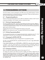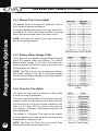
1
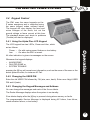
M1 ELECTRIC FENCE MONITOR Installation and User Manual 2nd Edition, 2013 JVA ELECTRIC FENCE SYSTEMS JVA Z Energizer Range Concept JVA ELECTRIC FENCE SYSTEMS Thank you for choosing our product. The JVA brand is a range of electric fencing products carefully selected from leading manufacturers around the world to meet the needs of perimeter security. THE JVA Z RANGE ENERGIZER CONCEPT The JVA Range of Energizers has been collaboratively designed and manufactured by an international team with over 30 years of electric fence experience earned in some of the most testing security environments in the world. It aims to provide the very best low-cost, high-voltage security energizers in the world. They are compact, integrated and fully programmable electric fence energizers with built-in alarm units and LCD out and return voltage display. They also have the option of being controlled from a remote LCD keypad. State-of-theart energizer design IP4 x and ABS plastic Unique LCD display depicting fence out and return voltage Unique LCD keypad option depicting fence and alarm condition 2-RyANrTY WAR Wall-mountable, robust energizer housing with easily detachable PCB chassis for ease of installation and repair TWO-YEAR WARRANTY All JVA products carry a 2-year warranty against defective components and workmanship. The warranty excludes damage caused by acts of Nature such as lightning or flooding, power supply surges, rough handling, malicious action or incorrect wiring. Please retain your invoice as proof of purchase and fill in the warranty form on page 32. JVA ELECTRIC FENCE SYSTEMS CONTENTS 1.INTRODUCTION........................................................................................3 2.FEATURES.................................................................................................5 2.1Limitations.........................................................................................5 3.OPERATION...............................................................................................6 3.1 Control Options ................................................................................6 3.2 Control Arbitration .............................................................................6 3.3 Control Inputs ...................................................................................6 3.4 Keypad Control..................................................................................7 Using the Alpha Plus LCD Keypad ......................................7 Changing the User PIN .....................................................7 Changing the Keypad Messages and Address ....................7 To Exit Keypad Programming ..............................................9 3.5 Jumper Configuration........................................................................10 3.6 LCD Display.......................................................................................11 3.7 Status LED Lights .............................................................................12 3.8 Front Label .......................................................................................12 4.SPECIFICATIONS......................................................................................13 Contents 3.4.1 3.4.2 3.4.3 3.4.4 5.INSTALLATION ..........................................................................................14 5.1 8 EHT Terminals on the ZM1 ............................................................14 5.2 Fence Wiring Diagrams.....................................................................15 5.2.1 5.2.2 5.2.3 5.2.4 Configuration with NO Return Wire from Fence ..................15 Earth Loop Monitoring .........................................................16 Earth Spike Monitoring ........................................................17 No Earth Monitoring .............................................................18 5.3 Low Voltage Terminals on the ZM1 ..................................................19 5.4 Low Voltage Wiring Diagrams...........................................................21 5.4.1 5.4.2 5.4.3 16Vac 2Amp Power Supply..................................................21 Controlling a 240Vac Energizer ...........................................22 External Battery and Charger...............................................22 1 JVA ELECTRIC FENCE SYSTEMS 6. PROGRAMMING OPTIONS ......................................................................23 6.1 Programming Basics ........................................................................23 6.1.1 6.1.2 6.1.3 6.1.4 Entering Programming Mode ...............................................23 Exiting Programming Mode .................................................23 Changing the Installer PIN ............................................23 Changing an Option .............................................................23 6.2 Programmable Options Table ...........................................................24 Contents 6.3 Programming Options in Detail ........................................................25 6.3.1 6.3.2 6.3.3 6.3.4 6.3.5 6.3.6 6.3.7 6.3.8 6.3.9 6.3.10 6.3.11 6.3.12 6.3.13 6.3.14 6.3.15 6.3.16 6.3.17 6.3.18 Fence Alarm Voltage Level (01x#) .......................................25 Current Alarm Level (02x#) ..................................................25 Ground Voltage Alarm Level (03x#) .....................................25 Missed Pulse Count (06x#) .................................................26 Battery Alarm Voltage (07x#) ...............................................26 Siren On Time (08x#) ...........................................................26 Siren Off Time (09x#) ...........................................................27 Siren Cycles (10x#) .............................................................27 Input Type (11x#) .................................................................27 Input 2 Function (12x#) ........................................................27 Gate Exit Delay (13x#) ........................................................28 Chime Mode (14x#) .............................................................28 Fence Mode (15x#) .............................................................28 Binary Options (16x#) ..........................................................29 Anti-Bridging Threshold (17x#) ............................................29 Auto Re-Arm Time (20x#) ....................................................30 Relay Functions ...................................................................30 Group Mode (26x#) .............................................................31 7.WARRANTY ..............................................................................................32 2 JVA ELECTRIC FENCE SYSTEMS 1.INTRODUCTION The combination of the ZM1 and the energizer operate in the same way as a single JVA Z series energizer, with the exception that the pulse power level of the energizer cannot be modified. Introduction The ZM1 is designed to be coupled with any standard electric fence energizer (see 2.1 Limitations below) to power and monitor an electric fence. As it can control very large energizers it is anticipated that the ZM1 will find application on large fences for game reserves and border security. The ZM1 uses Patent Pending, DFD™ technology to determine if there is a fault on very long fences. The ZM1 monitors the live feed line from the energizer to the fence and determines if the fence is working properly by measuring the voltage and current (therefore power) flowing to the fence. As such it does not require a return line from the end of the fence. This can represent a large saving on installation costs on new fences or make monitoring an existing fence possible if no return line was originally wired. The ZM1 can, however, also monitor the return if that is desired. The ZM1 has many programmable options which can be adjusted using a JVA Z series keypad. By correctly setting the alarm threshold levels it is possible to determine if a fence has been cut or shorted at any point. The ZM1 is designed to meet or exceed the relevant parts of IEC60335.2.76. The ZM1 is part of the JVA Z series of security energizers, designed and manufactured by Pakton Technologies. 3 JVA ELECTRIC FENCE SYSTEMS Equipment Requirements and Options Requirements • • • • An energizer 12V rechargeable backup battery 16Vac power adaptor OR external battery charger Security electric fence; standards, insulators, wire etc. Some of these items may be included with the ZM1. Introduction Options • 12V Siren and strobe light • LCD Keypad (PTE0210). Note 1,2 • Windows PC – Windows XP or Windows 7 – PAE223 USB to Keypad Bus or PAE212 TCP/IP adaptor – Perimeter Patrol PC application (Pro version) Notes: 1. While the Keypad is not essential for normal operation, it is always required for programming options during installation. 2. Up to 3 Keypads may be used with a ZM1, each Keypad must have a unique ID setting. For more information on these options please see www.jva-fence.com.au There are high voltages inside the ZM1 and JVA energizers. The high voltage inside the energizer may take a long time to discharge. Wait at least 10 minutes after turning off before opening the case. Before working on the high voltage wiring of an electric fence, it is recommended that the energizer is disarmed DANGER and a short circuit is placed from the fence live wires to earth. This is a sensible precaution against the energizer being armed while working on the fence. Note: The energizer manual must also be provided to the customer as it includes mandatory safety information. 4 The ZM1 contains patent pending technology. contact JVA for more information. JVA ELECTRIC FENCE SYSTEMS 2.FEATURES Features • Wall-mountable Z series energizer enclosure • Can be combined with any energizer (see 2.1 Limitations below) to produce a full featured security electric fence energizer/monitor • Distant Fault Detection (DFD)™ allows faults to be detected on very long fence lines (Note 1) • Anti-bridging mode, alarms on sudden change in load (Note 2) • Control and programmable via keypad with similar codes to the Z series • Monitor fence voltage and current to trigger an alarm if current rises or voltage falls (load increases) • Start and/or end of fence monitoring • Able to be monitored via PC (using Z control or Perimeter Patrol software) • Run from 16Vac or 12V DC external source • Built-in battery charger and 7aH back-up battery (not included) as per Z14 • Can be operated from alternative larger external battery and charger • Controls 12V DC feed to energizer • Can control a 240Vac energizer via external relay (not supplied) (12V coil, 240Vac rated contacts) • Remote on/off or keyswitch • Gate contact input • Siren and strobe switched 12V DC outputs • 3 on-board relays with many programmable functions. 2.1Limitations • An energizer used with the ZM1 must comply with IEC60335.2.76 (or similar) safety standard. • The ZM1 supports conventional wiring only (not Bi-Polar), although 2 units could be used to monitor a Bi-Polar fence. • The maximum energizer power is 36 Joules (Stafix M36 or similar). • At this stage (Code Version 1.4 and earlier) a ZM1 cannot be used in a group either with other ZM1 units or with Z series energizers. Notes: 1. DFD operates on PCB Versions 1.1 and higher and firmware 1.40 and higher. 2. Anti-bridging operates with firmware 1.32 or higher. 5 JVA ELECTRIC FENCE SYSTEMS 3.OPERATION 3.1 Control Options The ZM1 may be armed and disarmed (controlled) using a: Key switch or remote switch connected to the control input (IN1) Remote control radio receiver connected to IN1 Z Series Keypad JVA GSM module Windows PC running JVA Perimeter Patrol (Pro version) Low level interface (wired to control inputs and relay outputs) from a third party security alarm panel or Physical Security Information System (PSIM) • A high level interface Operation • • • • • • Note: More than 1 method may be used in the one installation. 3.2 Control Arbitration If an installation contains two ways to control the ZM1/Energizer, then the most recent control signal will determine the Armed/Disarmed state. For example, if the ZM1 is armed via the keypad, and then disarmed at the control input (IN1), it will disarm. The higher level control methods such as the GSM and PC control software may override the Control input and Keypads methods, depending on the options used. If you need to make sure that the fence is disarmed (for maintenance) then using the Key switch or keypad alone may not guarantee that the fence will remain disarmed. 3.3 Control Inputs The ZM1 may have a single Key switch mounted on the right hand side of the cabinet which may be used to arm and disarm the security electric fence to which it is connected. This switch is useful for the simplest implementations where no keypad or PC control program is used. It may be disabled by the installer, by removing the lead from socket SW2. When switched on via the Key switch (or a switch connected to IN1) the ZM1 will power up the energizer it is coupled to and begin monitoring the fence. The LCD display will change to display the Feed and Ground voltages. If there is a fence fault the ZM1 will go into alarm, the internal beeper will sound (if it has not been inhibited) and any siren and strobe connected to the ZM1 will be turned on. Switching the Key switch off will disarm the ZM1, though it will continue to display the alarm. 6 JVA ELECTRIC FENCE SYSTEMS 3.4 Keypad Control The ZM1 uses the same keypads as the Z series energizers and is controlled using the same keypad codes outlined below. The keypad will also display the feed and return voltages of the fence, but not the ground voltage or fence current at this time. The standard alarms and alerts to problems (Trouble) will also be displayed. 3.4.1 Using the Alpha Plus LCD Keypad The LCD keypad has two LED’s, Power and Arm, which act as follows: All other indication is given via messages on the screen. Whenever the keypad displays: • ALARM ZONE • FAULTED ZONE or • SYSTEM TROUBLE pressing the [#] key will reveal more information, such as the name of the zone or the actual system trouble, for instance AC Fail. Operation Power – On with mains power, flashes on low battery Arm – On when the ZM1 is armed. 3.4.2 Changing the User PIN Enter the old USER PIN followed by *0# (star, zero, hash). Enter new 4-digit USER PIN and # (hash). 3.4.3 Changing the Keypad Messages and Address You can change the messages and each of the 8 zone labels. The Dealer Message displays when the system is on standby. Zone labels display after the [#] key is pressed during alarm memory or faults. The programmable Service Message is displayed during AC failure, fuse failure, communication failure, or low battery. 7 JVA ELECTRIC FENCE SYSTEMS Keys used for changing messages [1] [2] Character up [3] not used Emergency not used [4] <- Cursor left [5] Next Message [6] -> Cursor right Fire not used [7] [8] Character down [9] Panic not used [*] [0] Last Message [#] Enter / Exit Bypass not used Operation • To activate the keypad programming mode, enter the [Installer’s PIN] [*] [0][1] [#]. Information may be entered into the keypad in the form of letters (upper and lower case), numbers (0 – 9), and 22 special symbols. All characters are displayed in the order: upper and lower case letters, numbers, and special symbols. The [Space] character precedes the letter A. • To enter a Label, use the [2] key to scroll through the characters until you reach the desired character. If you scroll past the desired character, the [8] key may be used to scroll backwards. Note: The space character is before the A character (When A is displayed, press [8] to create a space). • When the desired character is displayed, press the [6] key to move the cursor to the next character position. The [4] key moves the cursor to the left. • When all characters have been entered, press the [#] key to enter the message and move to the next message position. • Use the [0] key to move backward through the messages. • To change the keypad address, scroll through the messages until the keypad displays: Keypad Address then change the value by pressing [2] (up) or [8] (down). Validate by pressing # NOTE: If you move to the next message using [5] instead of the [#] key, you will lose any changes you made! Notes on keypad addresses: Up to 3 keypads can be used in a system. When using 2 or 3 keypads in a system, one of the keypads MUST be set to address 2 and the second one should be set to a value between 1 – 7. Do not set this to address 8 as this address uses a different protocol. If a third keypad is used, its ID must also be set to a unique value between 1 and 7. The message order is: • • • • • 8 SERVICE MESSAGE (Displayed under SYSTEM TROUBLE) DEALER MESSAGE (Displayed under the standby message: READY TO ARM) SOFT ZONE IDENTIFIERS (A, B, and C) (not used) HARDWIRED LOOP IDENTIFIERS (Zone 1 = Gate, Zone 3 = Fence) KEYPAD ADDRESS (should be left at 1 for energizers with firmware older than 7V51) JVA ELECTRIC FENCE SYSTEMS 3.4.4To Exit Keypad Programming When you have finished programming, press [*] [#] Note: The keypad will also exit the programming mode if you do not press any key within a five minute period. Summary of LCD Keypad Functions Key Sequence Arm/Disarm Silence an alarm (single zone system only) Start programming the Z series energizer Start programming the keypad Exit programming (any mode) Change a user PIN Change the installer PIN Arm All Zones (multi-zone groups) Arm Zone 1 (Master) Arm Zone 2 (on Z28 or Slave in group) Disarm All Zones Disarm Zone 1 or Master Disarm Zone 2 (on Z28 or Slave in group) Switch to low power mode (all zones) Switch to high power mode (all zones) [User PIN][#] [User PIN][#] [Installer PIN][*] [0] [#] [Installer PIN][*] [0] [1] [#] [*] [#] [User PIN][*]0[#][New PIN]# [0] [0] [New Installer PIN][#] [User PIN][*][1][0][#] [User PIN][*][1][1][#] [User PIN][*][1][2][#] [User PIN][*][2][0][#] [User PIN][*][2][1][#] [User PIN][*][2][2][#] [User PIN][*][4][1][#] [User PIN][*][4][2][#] To change the Keypad Messages to English To change the Keypad Messages to Spanish [*][3][1][#] [*][3][2][#] (not well supported yet) Keypad Audible Feedback Toggle Keypad Alarm Beeper (Chime) On/Off Keypad Error Tones Toggle On/Off Backlight Toggle On/Off Display Keypad Model Reset and display firmware version number Power Boost Siren test Battery test Clear Alarm memory [*] [5] [1] [#] [*] [5] [3] [#] [*] [5] [4] [#] [*] [8] [#] [*] [9] [#] [User PIN][*][6][8][#] [*] [9] [9] [#] [*] [6] [3] [#] [*] [6] [4] [#] only while dis-armed [*] [1] [#] Proposed Function Pre-warn toggle on/off Reset and return to factory defaults Emergency Proposed Key Sequence [*] [5] [2] [#] [Installer PIN][*] [6] [8] [#] Hold for 3 seconds. Operation Function 9 JVA ELECTRIC FENCE SYSTEMS 3.5 Jumper Configuration The ZM1 is equipped with four jumpers. Two of them (J3 and J4) are special purpose jumpers (links). The purpose of each is listed in the table below. Operation Jumper 10 Function Purpose J3 DC only jumper Remove J3 to inhibit mains fail errors if the intention is to operate the Z14 on DC only (as in Solar Power systems) J4 Factory default jumper If the monitor unit needs to be defaulted to factory settings, remove all power – mains and battery – and remove the J4 jumper. Reapply the battery power first, and then the mains power. Reapply the J4 jumper and the unit will be reset to default settings. If Status LED flashes four times after defaulting the unit, return it to the nearest JVA service centre. The 3rd jumper, J5, when fitted, will suppress the beeper on the ZM1. The fourth jumper (J6) allows the supply voltage for the energizer to be set. If the top two pins are selected (12V Regulated) then the energizer supply voltage will be the same as the PAE202 battery voltage (between 12 and 14.5 volts). If the bottom two pins are selected (24V Unregulated) the voltage supplied to the energizer will depend on the type and size of AC power adapter used, but may be as high as 24 volts. JVA ELECTRIC FENCE SYSTEMS mper Jumper Configuration Configuration 3.6 LCD Display CDLCD display display The LCD display on the ZM1 will switch between two different display modes. The mode shown can be identified by the feed and return LED’s on the status panel. The picture on the left below shows the feed mode, which shows the voltage at the start of the fence, and the current flowing into the fence. The picture on the right shows the voltage at the end of the fence, and the ground voltage. Note that the return voltage can be inhibited with programming option 15 if only the start of the fence is to be monitored. Operation 11 JVA ELECTRIC FENCE SYSTEMS 3.7 Status LED Lights Power – On whenever the unit has power Feed – Tells the user that the LCD is displaying the Feed Voltage (left) and Fence Current (right) Armed – On when the unit is armed (pulsing) Return – Tells the user that the LCD is displaying the Return Voltage (left) and Ground Voltage (right) Fence – On when there is a fence alarm (either channel) Gate – On when there is a gate alarm Ground – On when there is a ground alarm (specific meaning will vary depending on ground configuration) (Please refer to the installation chapter for more information.) Status – Flashes an error code for monitor (service) errors. These error codes are identical to the Z energizer range. The table below shows the Status LED Error Codes. Error LED Interpretation Number of Flashes 2 16Vac mains fail Restore mains power 3 Low battery, bad battery Charge or replace battery PCB service fault Return to repair/service centre. Note: A Z slave will show this error if disconnected from the Master. 4 3.8 Front Label As can be seen in the picture alongside, the front label clearly labels the different LED functions and LCD display modes. 12 Corrective Action Operation Operation The status LED’s on the front of the ZM1 allow the user to quickly ascertain the current status of the unit and if any action needs to be taken. Below is a brief description of each LED (from left to right, top to bottom) and the information it conveys. JVA ELECTRIC FENCE SYSTEMS 4.SPECIFICATIONS The specifications table below outlines the power consumption of the ZM1 and the acceptable voltage and current ranges for different inputs and outputs. Internal battery charger float voltage 14.3Vdc Internal battery charger charging current 580mA 85mA at 12.5Vdc 19Vac Maximum DC energizer current from ENERGIZER powered output if using 16Vac supply and internal battery 2.3 Amps Amps maximum DC energizer current from ENERGIZER powered output if using external power supply and battery 10 Amps Maximum voltage on In1, SW2 and Gate inputs (Note 2) Maximum power provided to Siren and Strobe outputs (Note 3) 5Vdc 35Watts Maximum fence voltage 9.9kV Maximum fence current 80 Amps Recommended operating temperature –15°C to +50°C Note 1: This is the power consumption when none of the powered outputs are active and the keypad is not connected. The rated power consumption may be lower depending on relay configuration and alarm states. Specifications Specifications Absolute maximum power consumption of ZM1 (Note 1) Maximum AC input voltage when internal battery charger is supplying 580mA Note 2: The control inputs, In1, SW2 and Gate supply their own power (5 volts, limited to 220 nA). If a powered control system is connected to these inputs, the control voltages must not exceed 5 volts. Note 3: The rated power is the combined output power of both the Siren and Strobe outputs. The voltage which can be expected on this output is the battery voltage. The combined maximum output current of both these outputs is 2.5 Amps. Note that the maximum output power will drop as battery voltage drops. 13 JVA ELECTRIC FENCE SYSTEMS INSTALLATION 5.INSTALLATION EHT terminals on the ZM: 5.1 EHT Terminals on the ZM1 Installation Description of high voltage terminals (left to right) EHT In Connect the high voltage output of the energizer to this terminal to allow fence current to be measured. Feed Connect the start of the fence to this terminal. Voltage at Feed will be the same voltage as EHT In. Return Connect the end of the fence to this terminal. The Return voltage will normally be lower than the Feed voltage. This terminal is unused at this time. Not Used Ground Ref Reference ground connection. Please refer to diagrams Earth Loop Monitoring, Earth Spike Monitoring and No Earth Monitoring for information on how to configure this input. Ground Main fence earth. Please refer to diagrams Earth Loop Monitoring, Earth Spike Monitoring and No Earth Monitoring for information on how to configure this input. 14 JVA ELECTRIC FENCE SYSTEMS 5.2 Fence Wiring Diagrams There are a number of ways the fence wires can be connected to a ZM1. The following diagrams will outline different ways in which the ground circuit can be configured and what the benefits of each are. 5.2.1 Configuration with NO Return Wire from Fence NOTE: Please refer to programming option Fence Mode (point 6.3.13) on page 28. JVA ZM1 ENERGIZER GROUND REF FEED HV IN JVA KEYPAD Installation m36 EARTH SPIKES 15 JVA ELECTRIC FENCE SYSTEMS 5.2.2Earth Loop Monitoring The set up pictured below will detect if the ground wire has been cut. Connect the Ground Reference input to the energizer Earth, and the Ground input to the other end of the earth fence loop. Feed/ Current/ Return Ground kV earth ground ground reference high voltage return feed High Voltage in Installation high power energizer CONVENTIONAL FENCE ENERGIZER EARTH 16 JVA ELECTRIC FENCE SYSTEMS 5.2.3Earth Spike Monitoring This setup will check how well the energizer is earthed. Connect the Ground Reference input of the ZM1 to the mains earth, or the cabinet earth. This Ground Reference must be more than 10m away from the Energizer Earth. Feed/ Current/ Return Ground kV high power energizer Installation ground ground reference earth return feed High Voltage in high voltage CONVENTIONAL FENCE ENERGIZER EARTH 17 JVA ELECTRIC FENCE SYSTEMS 5.2.4 No Earth Monitoring This setup will monitor only the fence feed and return voltages and fence current. Connect the Ground Reference and Ground inputs to each other with a short piece of wire. Feed/ Current/ Return Ground kV earth ground ground reference high voltage return feed High Voltage in Installation high power energizer CONVENTIONAL FENCE ENERGIZER EARTH 18 JVA ELECTRIC FENCE SYSTEMS 5.3 Low Voltage Terminals on the ZM1 voltage terminals on the ZM1 Installation el Type Description See page 20 for a table giving the Type and Description of each component labelled Energiser control input (dry contact). Defaults to normally open. above. Can be used for a remote switch or a radio receiver. The receiver may be powere from the keypad +12V terminal. 19 Installation JVA ELECTRIC FENCE SYSTEMS 20 Label Type Description IN1 2 Way Energizer control input (dry contact). Defaults to normally open. Can be used for a remote switch or a radio receiver. The receiver may be powered from the keypad +12V terminal. Gate 2 Way ZM1 Gate Input, when the unit is armed and the gate is opened, it will trigger the gate alarm. Keypad 3 Way Supplies power and data line for an external keypad. The +12 source on these terminals is protected with a 1A self resetting fuse. Siren 2 Way Switched 12 volt output. Low side switched. 35W max (including strobe). A buffer relay should be used when connecting these outputs to an alarm panel. Strobe 2 Way Switched 12 volt output. Low side switched. 35W max (including siren). A buffer relay should be used when connecting these outputs to an alarm panel. Energizer Power 2 Way Powered output which is enabled when the ZM1 is armed. Power is drawn from the ZM1 battery and 16Vac power supply, or from the EXT 12V input. EXT 12V 2 Way Input used for DC energizers which exceed the supply rating of the 16Vac transformer (greater than 12 Joules output). 16V AC IN 3 Way 16Vac power input. Fused via F3 3A self resetting fuse. Relay 3 3 Way May be set to any of 16 alarm conditions. Relay 4 3 Way May be set to any of 16 alarm conditions. Relay 5 3 Way May be set to any of 16 alarm conditions. Batt Leads 12V dc or battery connection via F1 (3 Amp self resetting fuse). Connect Red lead to battery positive (+) terminal. (not pictured on page 17) SW2 2 Way Energizer control input. Normally connected to a keyswitch (not pictured on page 17). JVA ELECTRIC FENCE SYSTEMS 5.4 Low Voltage Wiring Diagrams 5.4.1 16Vac 2Amp Power Supply + The ZM1 can be used to power an external high powered energizer. A 16Vac 2Amp power supply is able to power a B5, B8 or B12 (or equivalent) energizer as well as the ZM1 and keep the backup battery charged. - SLA 12Volt Battery BATT Feed/ Current/ Return Ground kV WARNING: The DC voltage supplied to the energizer will be the rectified voltage of the 16Vac which may be as high as 30Vdc. 16Vac high power energizer 16Vac 2A PSU high voltage earth Installation 12V Larger energizers will need to utilise the external 12 volt power supply input. 21 JVA ELECTRIC FENCE SYSTEMS 5.4.2 Controlling a 240Vac Energizer + The ZM1 can be used to power an external high-powered energizer. - SLA 12Volt Battery The ZM1 can control an external relay box designed to switch 110Vac or 240Vac powered energizers. The relay box needs to accept switching voltages of up to 13.8 volts. BATT Feed/ Current/ Return Ground kV WARNING: DO NOT use relay 3, 4 or 5 on the ZM1 to switch mains voltage. 12V 16Vac Installation high power energizer 16Vac 2A PSU 110/240Vac Input high voltage earth Mains Relay Box 5.4.3External Battery and Charger Larger 12Vdc energizers will need to utilise an external 12 volt power supply. BATT Feed/ Current/ Return Ground kV OUT IN 12V 12V 16Vac high power energizer (DC POWERED) high voltage External 13.8Vdc Charger 22 + - SLA 12Volt Battery earth To power the ZM1 from the external battery and charger, ensure Jumper J6 is placed on the 12V regulated pins. Do not connect a 16Vac supply to the ZM1. JVA ELECTRIC FENCE SYSTEMS 6.PROGRAMMING OPTIONS Like the Z series of security energizers, the ZM1 has a non-volatile memory in which programming options (or setup parameters) can be stored. These are factory pre-set, but can be field programmed using a keypad. Some of the programming options on the ZM1 are different to those on the Z series of security energizers, but the basic functions remain the same. 6.1.1Entering Programming Mode To enter programming mode, enter the 6 digit installer PIN followed by *0# keys. The keypad will beep twice to indicate that the command was accepted. If the PIN was incorrect the keypad will beep 3 times. The LCD will now show the first programming option and its current setting. Pressing the # key will cycle through all the options on the LCD. Note: Not all numbers are used. The default installer PIN is 012345. 6.1.2Exiting Programming Mode To exit programming mode once programming has been completed, press *# . If left unattended, the unit will time out and auto exit after approximately 5 minutes. 6.1.3 Changing the Installer PIN The installer PIN may only be changed while in programming mode. To enter a new installer pin, press 00 followed by the new 6 digit installer PIN, then the # key. If you cannot remember your installer or user PIN, return the units memory to default. To do this, remove power (AC off and disconnect the battery), open the energizer, remove jumper J4 and reconnect the battery for about 10 seconds. Do not forget to re-fit J4. This will return all options to the factory set defaults. Programming Options 6.1 Programming Basics 6.1.4 Changing an Option Most of the options have possible values in the range of 0 to 9. To change any options, first check the option number (see table on page 24) and then the Programming Options in Detail on page 25. Then press the option number followed by the required value. For example, to change the Missed Pulse Count (Option 06) to maximum (9 is the Maximum) press 069#, the keypad will beep twice to indicate that the command was successful. The ZM1 LCD will immediately show the updated value. 23 JVA ELECTRIC FENCE SYSTEMS Programming Options 6.2 Programming Options Table 24 Option Function Description 01 Fence alarm voltage level 02 Current alarm level 03 08 Ground Voltage alarm level Missed Pulse Count Battery Alarm Voltage Siren On Time 09 Siren Off Time 10 Siren Cycles 11 Input type 12 14 15 Gate Input Function Gate Exit Delay Chime Mode Fence Mode Sets the voltage below which the fence alarm will occur. If the feed OR return voltage falls below this level for more than the Missed Pulse Count a fence alarm (Zone 1) will occur. If the return voltage is not being used set option 15 to 1. Sets the threshold to alarm on current from the feed terminal to the fence. If the feed current rises above this level for more than the Missed Pulse Count a fence alarm (Zone 1) will occur. Sets the voltage above which the fence alarm will occur. If the ground voltage rises above this level for more than the Missed Pulse Count a ground alarm (Zone 2) will occur. Sets the number of pulses which may be missed before the alarm is activated. Sets the battery voltage threshold below which the general alarm will activate. Sets the time that the siren (and keypad beeper) will stay on after an alarm. The amount of time the siren will remain off after the On Time has expired. The number of times the siren will sound for the time set in On Time above. After this many cycles the siren will automatically mute. Allows the ZM1 inputs to be changed from normally open to normally closed. Gate switch only for now. 16 17 Binary Options Anti-Bridging 20 Auto Re-Arm Time 21 22 23 24 25 26 Relay 1 Relay 2 Relay 3 Relay 4 Relay 5 Group ID 06 07 13 Duration of time from gate switch opening to alarm. Allows the keypad and internal beeper function to be altered. Set to 1 if using start of fence only, removes return voltage from display and alarm. Miscellaneous options Sets the % threshold for alarm on a sudden rise or fall of fence current. Sets the time which must elapse after an alarm has timed out (completed the siren cycles) before the unit will automatically re-arm ready for the next alarm event. Used to assign an alarm function to relay 1 (siren output) Used to assign an alarm function to relay 2 (strobe output) Used to assign an alarm function to relay 3 Used to assign an alarm function to relay 4 Used to assign an alarm function to relay 5 If used as part of a SCADA system, this sets the device ID JVA ELECTRIC FENCE SYSTEMS 6.3 Programming Options in Detail Note: The bold panel in each table indicates the default value. 6.3.1 Fence Alarm Voltage Level (01x#) Unlike the other Z series energizer the value is set directly, not via a table. For example to set a threshold of 5.0kV enter: 0 1 5 0 # (Do not enter the decimal!) The default level is 4.0kv (40). Value (x) Minimum 0 Maximum 99 Alarm Level 0.0 kV 9.9 kV Fence Alarm Voltage Level (01x#) 6.3.2 Current Alarm Level (02x#) This option sets the threshold to alarm on current from the feed terminal to the fence. If the feed current rises above this level for more than the Missed Pulse Count a fence alarm (Zone 1) will occur. Unlike the other Z series energizer, the value is set directly, not via a table. For example to set a threshold of 5A enter: 0 2 0 5 # The default level is 10A. Value (x) Minimum 0 Maximum 75 Alarm Level 0 Amps 75 Amps Current Alarm Level (02x#) 6.3.3 Ground Voltage Alarm Level (03x#) This option sets the voltage above which the fence alarm will occur. If the ground voltage rises above this level for more than the Missed Pulse Count a ground alarm (Zone 2) will occur. Unlike the other Z series energizer, the value is set directly, not via a table. For example, to set a threshold of 2.0kV enter: 0 3 2 0 # Do not enter the decimal! The default level is 1.0kv (10) Value (x) Minimum 0 Maximum 50 Alarm Level Programming Options This option sets the voltage below which the fence alarm will occur. If the feed OR return voltage falls below this level for more than the Missed Pulse Count a fence alarm (Zone 1) will occur. If the return voltage is not being used, set option 15 to 1. 0.0 kV 5.0 kV Ground Voltage Alarm Level (03x#) 25 JVA ELECTRIC FENCE SYSTEMS 6.3.4 Missed Pulse Count (06x#) The Missed Pulse Count option is identical to that of the Z series of security energizers. Programming Options This option enables the pulse count to be varied from the default (3). This is the number of bad or missing pulses that are counted before the alarm occurs. Note: The lower this option is set, the more likely you are to get false alarms 6.3.5 Battery Alarm Voltage (07x#) This option sets the battery voltage threshold below which the general alarm will activate. The default Battery Alarm Voltage is 10.0 Volts. This alarm can be set to activate one of the relays, and is part of the General alarm, see below. Note: The ZM1 will not turn the energizer off when the battery voltage is low. But if the supply voltage falls too low the relay powering the external energizer will eventually drop out. 6.3.6Siren On Time (08x#) The Siren On Time option is identical to that of the Z series of security energizers. This option sets the duration of time that the siren will remain on after a fence alarm occurs. After this time the siren will turn off for the off time indicated in the table in 6.3.7 Siren Off Time Values. The siren will sound again if the alarm is still present after this off time has passed. The default is 3 Minutes. This may be the subject of local regulations to stop an alarm causing undue disturbance to neighbours, etc. 26 Note: The Siren On Time will be cut short if the battery falls below the low battery level. Value (x) 0 1 2 3 4 5 6 7 8 9 Missed Pulses 1 1 2 3 4 5 6 7 8 9 Missed Pulse Count (06x#) Value 0 1 2 3 4 5 6 7 8 9 Alarm 9.0V 19.5V 10.0V 10.5V 11.0V 11.5V 12.0V 12.5V 13.0V 13.5V Battery Alarm Voltage (07x#) Value 0 1 2 3 4 5 6 7 8 9 Time 10 Seconds 30 Seconds 1 Minute 2 Minutes 3 Minutes 4 Minutes 5 Minutes 6 Minutes 7 Minutes 8 Minutes Siren On Time (08x#) JVA ELECTRIC FENCE SYSTEMS 6.3.7Siren Off Time (09x#) 6.3.8Siren Cycles (10x#) Siren On Time (09x#) The Siren Cycles option is identical to that of the Z series of security energizers. This option sets the maximum number of times the siren will sound for the On Time if the alarm continues. This may be limited by local regulations to stop an alarm causing undue disturbance to neighbours, etc. Note: This is the maximum number of cycles for 1 continuous alarm. Intermittent alarm events could cause more than this number of siren soundings. 6.3.9 Input Type (11x#) Value 0 1 2 3 4 5 6 7 8 9 Time 10 Seconds 1 Minute 2 Minutes 5 Minutes 10 Minutes 20 Minutes 30 Minutes 40 Minutes 50 Minutes 60 Minutes Cycles 1 1 2 3 4 5 6 7 8 9 Siren Cycles (10x#) The Input Type option is identical to that of the Z series of security energizers. Value 0 The control inputs can be inverted unless an input is used for a Gate switch, in which case it is always NC. 1 Input type NO Normally Open NC Normally closed Programming Options This option sets the amount of time the siren will be off for after the on time above has expired. If an alarm is still present after this off time the siren will sound again. Value 0 1 2 3 4 5 6 7 8 9 The Siren Off Time option is identical to that of the Z series of security energizers. Input Type (11x#) 6.3.10 Gate Input Function (12x#) This input can not be configured to anything other than a Gate input at this time. 27 JVA ELECTRIC FENCE SYSTEMS 6.3.11 Gate Exit Delay (13x#) Programming Options The Gate Exit Delay option is identical to that of the Z series of security energizers. This option sets the time between the gate switch opening and the siren sounding. 28 6.3.12 Chime Mode (14x#) The Chime Mode option is identical to that of the Z series of security energizers. This option allows the energizer internal and keypad beeper to be used as a door chime for the gate switch. When set to None, the keypad beeper is used to indicate correct keypad operation only. In Door Chime mode, the beepers sound when the gate switch opens, even if the energizer is disarmed. Note: Gate must be selected in option 12. If set to Siren, the beepers mimic the siren function. Gate Beeps plus Siren will give 2 beeps when the gate starts opening and 4 beeps when it closes, plus continuous beeps for an alarm. Beeps are on the keypad only, not on the internal beeper. Value 0 1 2 3 4 5 6 7 8 9 Function 0 Seconds (immediate) 30 Seconds 1 Minute 2 Minutes 3 Minutes 4 Minutes 5 Minutes 6 Minutes 7 Minutes 8 Minutes Gate Exit Delay (13x#) Value 0 1 2 3 4 Function None Door Chime Siren Fence Alarm Gate Beeps plus Siren Chime Mode (14x#) 6.3.13 Fence Mode (15x#) This option configures if the return voltage should be monitored. If set to 1, this option will stop the return voltage from being displayed on the LCD, and inhibit any alarms which may normally be triggered owing to no voltage being present on the return input. Value 0 1 Function Monitor Return Feed only Fence Mode (15x#) JVA ELECTRIC FENCE SYSTEMS 6.3.14 Binary Options (16x#) Each option in this table can be turned on by adding the value. For option +1 set 16 to 01, for +1 and +2 set 16 to 03. Value 0 +1 Function None Engage DFD* +1: Enable DFD™ (Distant Fault Detection). Firmware V1.40 and later, PCB V1.10 and later. * DFD™ is Trade Mark and Patent Pending by Ex-PT Pty Ltd. 6.3.15 Anti-Bridging Threshold (17x#) Anti-Bridging has been designed to detect a section of fence being bypassed, and removed, by an intruder bridging the adjacent fence sections together. This also detects when the feed is connected to the return with a short cable, and then the entire fence is cut. Setting this option to a value greater than 0 (default is 0 = off) will enable Anti-Bridging. Value (x) Minimum 0 Maximum 90 Threshold Disabled 90% Anti-Bridging Threshold (17x#) While Armed, a Fence Alarm will trigger if the Fence Current rises OR falls quickly by more than the threshold. A slow change to the Current will not trigger a Fence Alarm until the Current is more than the Current Alarm Level (02x#) The Anti-Bridging Threshold is a percentage value of the Fence Current. For example, setting option 17 to 50 (1750#) will set a 50% Anti-Bridging Threshold. At this level a Fence Current normally reading 10Amps will trigger a Fence Alarm if the Current quickly rises to over 15A or falls to less than 5A. Programming Options DFD™ enables the ZM1 to detect a fault at the end of very long fences. Instead of only measuring the Binary Options (16x#) peak current the ZM1 with DFD™ calculates the “real” current and rejects the “reactive” current. The current displayed will usually be less than read by a standard hand-held meter with this feature on. There is no theoretical limit to the length of fence that the ZM1 can monitor with this feature on. Without DFD™ the limit is approximately 8km. Measuring fence current to determine if a fence is bridged will work irrespective of the energizer type powering the fence. 29 JVA ELECTRIC FENCE SYSTEMS 6.3.16 Auto Re-Arm Time (20x#) The Auto Re-Arm Time option is identical to that of the Z series of security energizers. Programming Options This option sets the time which must elapse before another alarm will sound after the first alarm has timed out (gone completely through its cycles). If an event occurs (such as a low fence voltage) which triggers the siren, any other events which would otherwise trigger the siren (such as a gate alarm) will be ignored while the siren is sounding and until after the Auto Re-Arm time has passed. A setting of 9 will disable auto Re-Arm. If this time is set to less than the Siren Off Time, the unit may re-arm in the siren off time and the number of siren cycles will be reduced. Value 0 1 2 3 4 5 6 7 8 9 Function 0 Seconds (immediate) 30 Seconds 1 Minute 2 Minutes 3 Minutes 4 Minutes 5 Minutes 6 Minutes 7 Minutes Disabled – Do not auto re-arm Auto Re-Arm Time (20x#) 6.3.17 Relay Functions All relays can be set to any of the available functions (user assignable). Relay 1 is (21x#) Relay 2 is (22x#), etc Defaults for the ZM1: • • • • • Relay 1 Relay 2 Relay 3 Relay 4 Relay 5 – – – – – Siren Strobe Fence 1 Armed General Note: The siren and strobe switched 12V outputs can be used to drive external buffer relays. Value 0 1 2 3 4 5 6 7 8 9 10 11 12 13 14 15 16 Function Fence 1 Fence 1 or off Armed 1 Ground Voltage Ground Voltage or Off Not used Bi-Polar General Siren Strobe AC Fail Low / Bad Battery Tamper Not used Gate Alarm Siren caused by Gate Not used Relay Functions 30 JVA ELECTRIC FENCE SYSTEMS Function Logic for alarm state (opposite of normal state) Fence alarm The ZM1 is Armed AND the fence voltage has fallen below the Fence Alarm Voltage Leve l (Option 01) for more pulses than the Missed Pulse Count. Not latched. Fence alarm or off The ZM1 is Disarmed OR the ZM1 is Armed and fence voltage has fallen below the Fence Alarm Voltage Level for more pulses than the Missed Pulse Count. Not Latched. Armed The ZM1 is Armed. General AC fail OR Tamper OR Low battery OR internal error. Latched for internal errors only. Siren Fence alarm 1 OR fence alarm 2 OR Gate Or Tamper, will time out after the siren time out time. This function is latched. Strobe As per siren but does not time out, will remain on until the ZM1 is Disarmed. This function is latched. AC Fail Alarm on AC fail. Battery Alarm on low or bad battery. Tamper Not applicable to the ZM1. 6.3.18 Group Mode (26x#) At this time it is not possible to connect ZM1s into a group. Since the ZM1 cannot control the pulse timing of an attached energizer it cannot be grouped for the purposes of synchronising. Nor can it be included in a group with other Z series energizers. It may be necessary to change 26 to 1 to enable PC control of the ZM1. Value 0 1 2 3 4 5 6 7 8 9 Function No Group Master Slave 1 Slave 2 Slave 3 Slave 4 Slave 5 Slave 6 Slave 7 Slave 8 Programming Options Fence Bipolar Not applicable to the ZM1. Group Mode (26x#) INSTALLER DETAILS Name ......................................................... Phone No. ................................................. Date Of Installation .................................. CUSTOMISED CODES Customer Pin No. .................... Installer Pin No: ....................... 31 JVA ELECTRIC FENCE SYSTEMS 7.WARRANTY All JVA products carry a 2-year warranty against defective components and workmanship. The warranty excludes damage caused by acts of Nature such as lightning or flooding, power supply surges, rough handling, malicious actions or incorrect wiring. Whilst every effort has been made to check that the information contained in this manual is accurate, JVA Technologies Pty Ltd will not be liable to loss or damage resulting from construction, operation or failure of any installation or system. Installation of security electric fences should be made by trained professionals with regard to the relevant local standards and workplace health and safety requirements. Warranty Product model purchased: ................................... Serial No.: ........................... Customer Name: ................................................................................................... Address: ................................................................................................... ................................................................................................... ................................................................................................... Postal Code: ........................................ Tel. No.: Cell: .................................Landline: ..................................... email: ................................................................................................... Date purchased: ......................................... Invoice No.: ......................................... Dealer Name: ................................................................................................... Dealer’s Stamp 32 Mail to your local JVA Dealer: RSA JVA Service Department, P.O. Box 13898, Cascades 3202 Republic of South Africa JVA ELECTRIC FENCE SYSTEMS Z-RANGE Z14 RANGE FEATURES INCLUDE Z14 STANDARD AND BI-POLAR ENERGIZERS LCD voltage display Powerful 4 joules per zone peak output energy Designed to pass IEC60335.2.76 and EMC 9.2 9.0 Z18 Z18 STANDARD AND BI-POLAR ENERGIZERS GSM MONITORS AND CONTROLS JVA ENERGIZERS USING A CELL PHONE standards (reports available on request) Wall mountable, robust enclosure with detachable PCB chassis for ease of installation and repair Earth monitor input Gate input Key-switch Keypad programmable Lower-power mode Entry/Exit delay from gate input trigger Switched +12V outputs for Siren and Strobe (up to 30 Watts for 3 minutes) Microprocessor controlled Outputs may be wired for BiPolar fences (excluding Z28) Multiple single-zone energizers can be wired as a group WEB SERVER MONITORS AND CONTROLS ENERGIZERS VIA THE INTERNET Z28 Z28 STANDARD 2-ZONE ENERGIZER PERIMETER PATROL COMPLETE CONTROL SYSTEM MONITORING EVENT LOGGING Customer Support For assistance: If you have any questions or need further assistance, please call your nearest JVA dealer. RSA Tel. No.: 0861 782 349. For service or repairs: If a service or repair is required, please package and label your energizer carefully and return it to your local JVA Service Centre. For warranty repairs: Include proof of purchase, e.g. invoice. Note: Repair centre details are displayed on the back cover of this manual. JVA ELECTRIC FENCE SYSTEMS JVA products are designed by JVA Technologies, Queensland, Australia and distributed to: AUSTRALIA AFRICA NEW ZEALAND LATINO AMERICA CARIBBEAN SOUTH EAST ASIA EUROPE RUSSIA INDIA USA MEXICO CENTRAL ASIA UNITED KINGDOM JVA SA SERVICE CENTRES East Rand (Jet Park) Cape Town North Rand (Kya Sand) Polokwane Aerostar Business Park 219 Jet Park Road, Jet Park Tel: 011 397 3507 174 Bernie Street Randburg Tel: 011 708 6442 West Rand (Roodepoort) 602 Ontdekkers Road Delaréy, Roodepoort Tel: 011 472 8823 Pretoria Unit 15, Viking Business Park Viking Way, Epping Industria Tel: 021 534 5056 Shop 11, Arcadia Centre 87 Umhlanga Rocks Drive Tel: 031 563 0274/ 031 563 6478 19A Suez Street Nirvana Tel: 015 292 6273 Pietermaritzburg Nelspruit Port Elizabeth D1 Waterfall Park 15 Rapid Street Riverside Industrial Park Tel: 013 752 7152 1185 Steve Biko Road (977 Voortrekker Road) Wonderboom South Tel: 012 335 4290 Bloemfontein Kimberley Unit 1, 7 Suffert Street Tel: 031 702 6351 29 Schmidtsdrift Road Tel: 053 861 5631 Durban North 51 Winston Road Tel: 033 342 6727 45 Mangold Street Newton Park Tel: 041 365 7178 East London 36 Kolbe Lane Tel: 051 448 6695 Shop 3, Paphos Park Devereaux Avenue Tel: 043 726 6652/60 Pinetown George Rustenburg Shop 3, 57 York Road George Tel: 044 874 0669 1 Howick Avenue, Shop 7, Waterfall Mall Tel: 014 537 2884 Nearest RSA branch: 0861 782349 • Website: www.jvasecurity.com • e-mail: [email protected]